

Page 1
TASCAM
TEAC
Audio
Mixer
Production Products
OPERATION /MAINTENANCE
Page 2
Page 3
IN'TRODUCTION T0 THE MODEL
35
The Model 35 is an audio mixing console designed to satisfy the requirements of modern multichannel recording. Many of the auxiliary mixing
systems needed are built-in and can be re-routed
to do more than one job. Fast, convenient and
complete operation with
can usually be accomplished without re-patching.
However, the process of multichannel recording
is
constantly changing, growing more complex
an art with each advance in technology. Your
signal processing needs may
arrangement of subsystems. No console has ever
been built so large and complete in
that it could
with one button. Someone
come up with that unusual situation requiring
"just one more mix". In order to copewith
solve every imaginable problem
4-
or 8-track recorders
require a unique
its
routing
will always be able to
thesep
as
unpredictable requirements, patch points are
provided throughout
M -35.
As our mixing console becomes more flexible,
the amount of
available function increases
signal path from mic in to line out
straightforward. The requirements
changed much
routing for effects sends,
monitoring
often overlooks the
that would be immediately obvious to the
rienced recording engineer. If you expect to find
that "extra rnix" quickly, you must be prepared
to study the layout of the M -35 thoroughly.
since the days of "mono", but the
can be hard to visualize. 'rhe beginner
al1 signal pathways on the
time needed to understand the
as
well. The main
is
still fairly
have not
cue feeds, and stereo
significance of connections
expe-
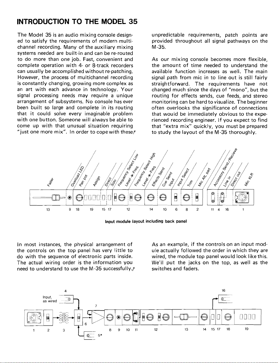
Input module layout including back panel
In most instances, the physical arrangement of
the controls on the top pane1 has very little to ule actually followed the order in which they are
do with the sequence of electronic parts inside. wired, the module top
The actual wiring order
need to understand to use the M -35 successfully~
is
the information you We'll put the jacks on the top,
As an example, if the controls on an input
pane1 would look Iikethis.
as
switches and faders.
mod-
well as the
Page 4
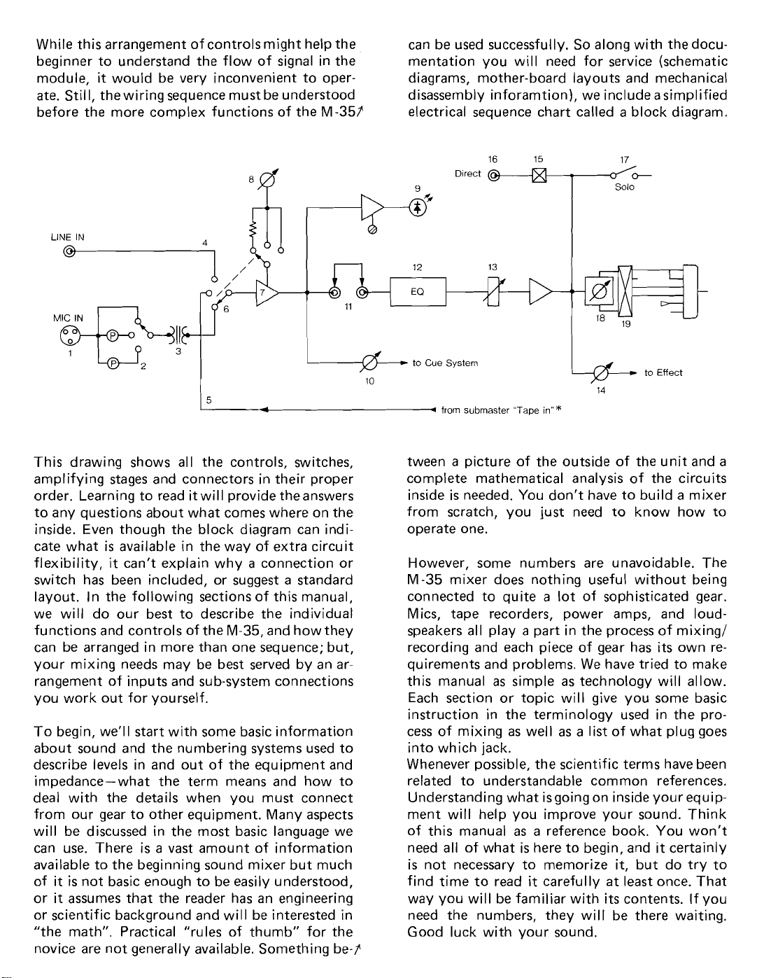
While this arrangernent of controls rnight help the
beginner to understand the flow of signal in the
it
rnodule,
StiII, the wiring sequence rnust be understood
ate.
would be very inconvenient to oper- diagrarns, rnother-board layouts and rnechanical
can be used successfully. So along with the docurnentation you
disassernbly inforarntion), we include
will need for service (schernatic
asirnplified
before the more cornplex functions of the M-35P electrical sequence chart called a block diagrarn.
This drawing shows al1 the controls, switches,
arnplifying stages and connectors in their
proper
order. Learning to read it will provide theanswers
to any questions about what cornes where on the
inside. Even though the block diagrarn
is
cate what
flexibility,
available in the way of extra circuit
it
can't explain why a connection or
can indi-
switch has been included, or suggest a standard
layout. In the following sections of this rnanual,
we will do our best to describe the
individua1
functions and controls of the M-35, and how they
can be arranged in more than one sequence; but,
your rnixing needs rnay be best served by an
ar-
rangernent of inputs and sub-systern connections
you work out for yourself.
To begin,
we'll start with some basic inforrnation
about sound and the nurnbering systerns used to
describe
levels in and out of the equiprnent and
impedance-what the terrn rneans and how to
dea1 with the details when you rnust connect
frorn our gear to other equiprnent. Many aspects
will be discussed in the rnost basic language we
can use. There
is
a vast arnount of inforrnation
available to the beginning sound rnixer but rnuch
of it
is
not basic enough to be easily understood,
or
it
assurnes that the reader has an engineering
or scientific background and wil
"the rnath". Practical
"rules of thurnb" for the
l
be interested in
novice are not generally available. Sornething be-7'
9
-
16
Direct
@
from
subrnaster "Ta~e
ml
15
inn*
17
-
P
solo
14
tween a picture of the outside of the unit and a
complete rnathernatical
inside
is
needed. You don't have to build a mixer
frorn scratch, you
analysis of the circuits
just need to know how to
operate one.
However, some nurnbers are unavoidable. The
M-35 rnixer does nothing
connected to
quite a lot of sophisticated gear.
Mics, tape recorders, power amps, and
useful without being
loudspeakers al1 play a part in the process of rnixingl
recording and each piece of gear has its own requirernents and problerns. We have tried to rnake
this rnanual
as sirnple as technology will allow.
Each section or topic will give you some basic
instruction in the terrninology used in the
process of rnixing as well as a list of what plug goes
into which
jack.
Whenever possible, the scientific terrns have been
related to understandable cornrnon references.
Understanding what isgoing on inside your
equiprnent will help you irnprove your sound. Think
of this rnanual
need al1 of what
is
not necessary to rnernorize
find tirne to
way you will be farniliar with
as a reference book. You won't
is
here to begin, and it certainly
it,
but do try to
read
it
carefully at least once. That
its
contents. If you
need the nurnbers, they will be there waiting.
Good luck with your sound.
Page 5
'THE
DB;
WHO, WHAT, WHY
No matter what happens to the signal while
it
being processed,
again by
a
human ear. So the process of convert-
will eventually be heard once
it
is
ing a sound to an electrical quantity and back to
sound again must follow the logic of human hearing.
The first group of scientists and engineers to dea1
with the problems of understanding how the ear
works were telephone company researchers, and
the results of their investigations form the
foundation of al1 the measurement systems we use in
audio today. The folks at Bell Laboratories get
the credit for finding out how we
power, how quiet a sound an average person
hear, and almost
al1
of the many other details
about sound you must know before
with it
successfully.
judge sound
can
you can work
From this basic research, Bell Labs developed a
system of units that
of the system. Sound traveling on wires as
could be applied to al1 phases
electrical energy, sound on tape as magnetic energy,
sound in air; anyplace that sound
stored as energy until some future
will again be sound,
can be described by using
the human ear-related system of numbers
is,
or has been
time when it
called
"bels" in honor of Alexander Graham Bell, the
inventor of the telephone.
is
What
a bel and what does it stand for?
it
is
loud? No,
only 6dB more sound. The unit
quantities must follow nonlinear progressions to
satisfy the ears' demand.
Remember, decibels follow the ears.
All other
quantities of measure must be increased in whatever units necessary to satisfy the human
require-
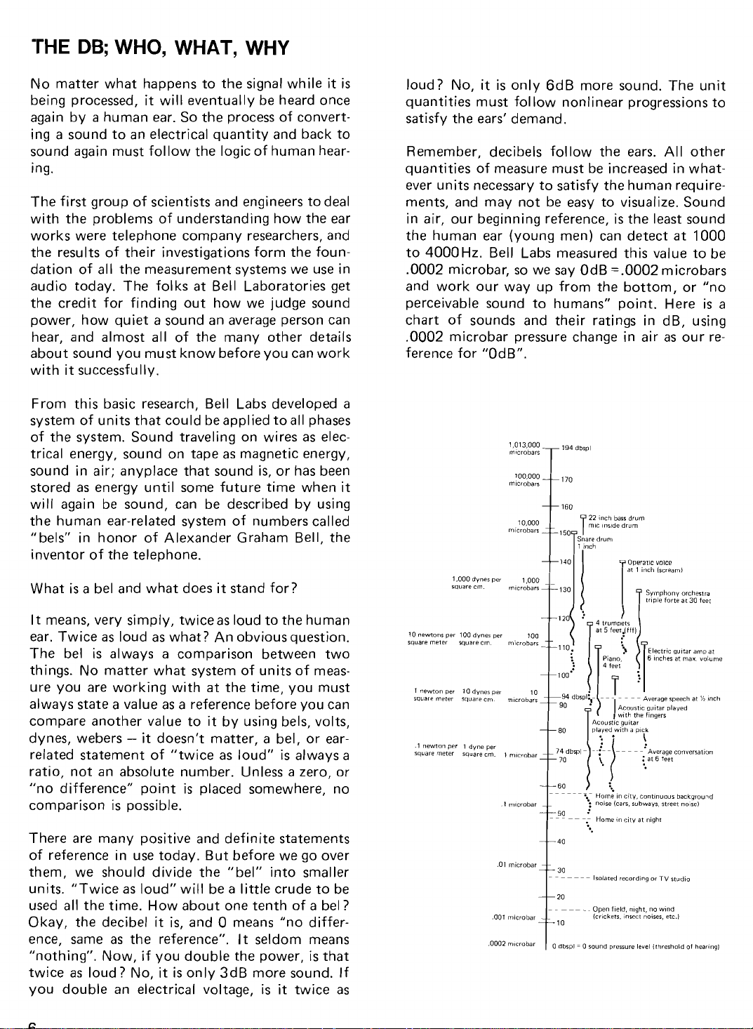
ments, and may not be easy to visualize. Sound
is
in air, our beginning reference,
the human ear
to
4000Hz. Bell Labs measured this value to be
(young men) can detect
the least sound
at
1000
.O002 microbar, so we say OdB = .O002 microbars
and work our way
perceivable sound to humans" point. Here
chart of sounds and their ratings in
up from the bottom, or "no
is
dB, using
a
.O002 microbar pressure change in air as our reference
for "OdB".
10,000
pnare druni
t140
1
22
nch
mic inride drum
l
inch
I
bass
drum
powr?Ilc voice
at
1
inch
Ircream)
It means, very simply, twice
ear. Twice
The bel
as
loud as what? An obviousquestion.
is
always a comparison between two
things. No matter what system of units of
ure you are working with
always state a value as a reference before you
compare another value to
-
it
dynes, webers
doesn't matter, a bel, or ear-
related statement of "twice as loud"
as
loud to the human
at
the time, you must
it
by using bels, volts,
is
always a
meas-
can
ratio, not an absolute number. Unless a zero, or
"no
difference" point
is
placed somewhere, no
comparison is possible.
There are many positive and definite statements
of reference in use today. But before we go over
them, we should divide the "bel" into smaller
units. "Twice
used
al1 the time. How about one tenth of a bel?
Okay, the decibel
ente,
same as the reference".
"nothing". Now, if you double the power,
twice
as
you double an electrical voltage,
as
loud" will be a little crude to be
loud? No,
it
is,
and O means "no differ-
It
seldom means
it
is
only 3dB more sound. If
is
it
is
that
twice as
10
-1
rquare
newtoiir
newton
rneter
per
per
100
1
square
dvner
dyne
per
100
per
cm. l niicrobar
I
microbar
.O1
microbar
-001
microbar
100'
--
-
...
Home in citv, cantinuour background
:
1
- - - - - -
noire*(carr,
-
"
Homen citv at night
t"
Isoiared recording
Open
icricketr.
rubwavr. rtreet
field, night,
nrect
Auerage
or
no
noirer,
converratlun
TV
studio
wind
etc.)
nolre)
Page 6
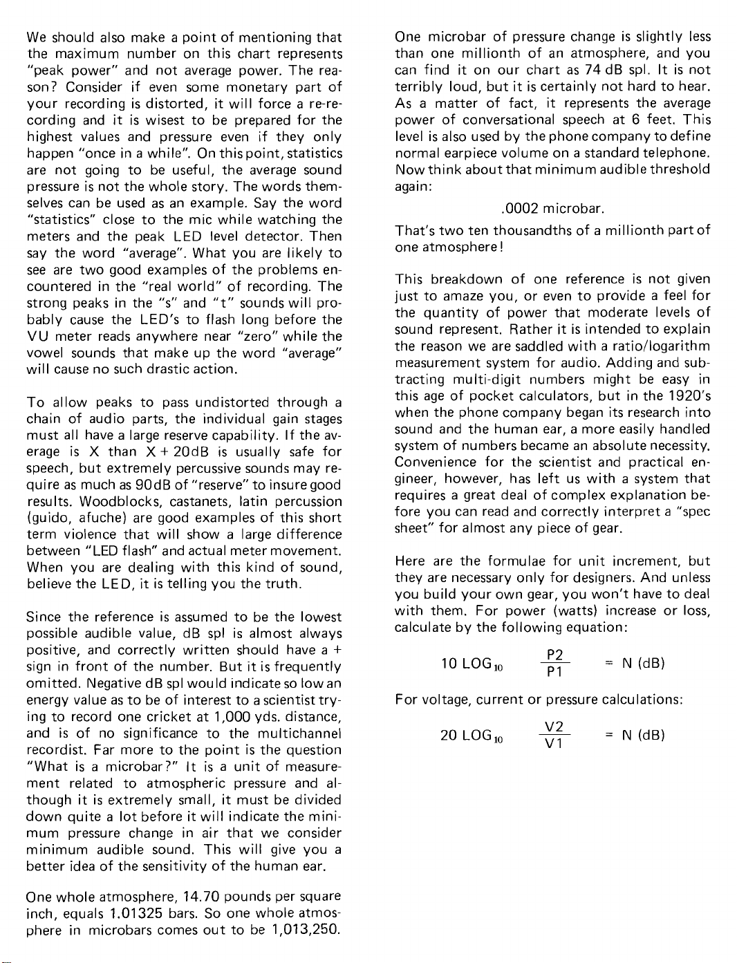
We should also make a point of mentioning that
the maximum number on this chart represents
"peak power" and not average power. The
reason? Consider if even some monetary part of
your recording is distorted, it will
cording and
it
is
wisest to be prepared for the
force a re-re-
highest values and pressure even if they only
happen "once in
a
while". On this point, statistics
are not going to be useful, the average sound
pressure
selves
"statistics" close to the
is
not the whole story. 'rhe words them-
can be used
as
an example. Say the word
mic while watching the
meters and the peak LED level detector. Then
say the word "average". What you are
see are two good examples of the problems
likely to
encountered in the "real world" of recording. 'rhe
strong peaks in the
"s"
and
"t"
sounds will probably cause the LED's to flash long before the
VU meter reads anywhere near "zero" while the
vowel sounds that make up the word "average"
will cause no such drastic action.
To
allow peaks to pass undistorted through
chain of audio parts, the individua1 gain stages
must
al1
have a large reserve capability. If the average
speech, but extremely percussive sounds may
qui re
results. Woodblocks, castanets,
is X than
as
much
X
+
20dB is usually safe for
as
90dB of "reserve" to insure good
latin percussion
re-
(guido, afuche) are good examples of this short
term
violence that will show a large difference
between "LED flash" and actual meter movement.
When you are dealing with this kind of sound,
it
believe the LED,
is telling you the truth.
Since the reference is assumed to be the lowest
possible audible value,
positive, and correctly written should
sign in front of the number. But
omitted. Negative
energy value
as
to be of interest to a scientist try-
dB spl is almost always
have
a
+
it
is
frequently
dB spl would indicate so low an
ing to record one cricket at 1,000 yds. distance,
and
is
of no significance to the multichannel
is
recordist. Far more to the point
"What is
a
microbar?" It
is a unit of measure-
the question
ment related to atmospheric pressure and although it
down
is
extremely small, it must be divided
quite a lot before
it
will indicate the minimum pressure change in air that we consider
minimum audible sound. This will give you
better idea of the sensitivity of the human ear.
One microbar of pressure change is
slightly less
than one millionth of an atmosphere, and you
can find it on our chart as 74 dB spl. It is not
terribly loud, but
As
a
matter of fact,
power of conversational speech
level is
also used by the phone company to define
it
is certainly not hard to hear.
it
represents the average
at
6
feet. This
norma1 earpiece volume on a standard telephone.
Now think about that minimum audible threshold
again:
.O002 microbar.
That's two ten thousandths of
one atmosphere
!
This breakdown of one reference
just to amaze you, or even to
the quantity of power that moderate
sound represent. Rather it is intended to
a
millionth part of
is
not given
provide a feel for
levels of
explain
the reason we are saddled with a ratiollogarithm
measurement system for audio. Adding and subtracting multi-digit numbers might be easy in
a
this age of pocket calculators, but in the 1920's
its
when the phone company began
sound and the human ear,
a
more easily handled
research into
system of numbers became an absolute necessity.
Conveniente
for the scientist and practical en-
gineer, however, has left us with a system that
a
requires
great dea1 of complex explanation before you can read and correctly interpret a "spec
sheet" for almost any
piece of gear.
Here are the formulae for unit increment, but
they are necessary only for designers. And unless
you build your own gear, you won't
have to dea1
with them. For power (watts) increase or loss,
calculate by the following equation:
10
LOG,,
For voltage, current or pressure calculations:
LOG,,
20
a
v2
v1
=
N
(dB)
One whole atmosphere, 14.70 pounds per square
inch, equals 1.01325 bars. So one whole
atmos-
phere in microbars comes out to be 1,013,250.
Page 7
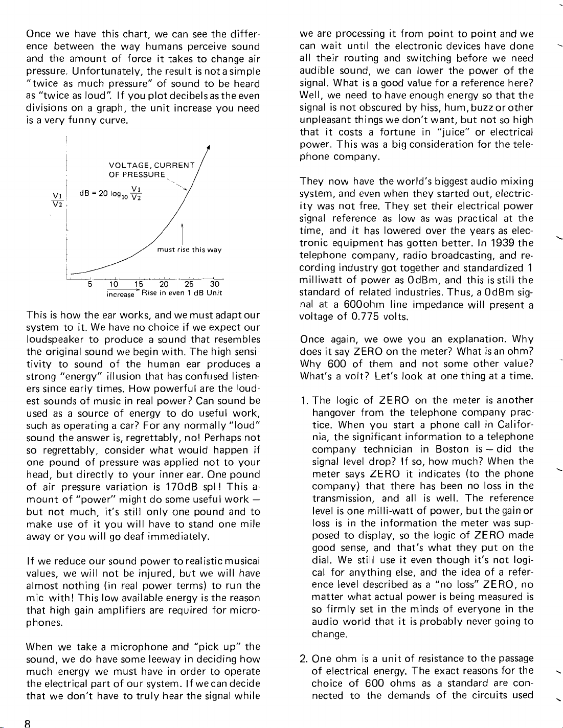
Once we have this chart, we can see the differ-
ente
between the way humans perceive sound
and the amount of
pressure. Unfortunately, the
"twice
as
divisions on
is
This is how the ear works, and we must adapt our
system to it. We
loudspeaker to produce
the
tivity to sound of the human ear produces
strong "energy" illusion that has confused listeners since early times. How powerful are the loudest sounds of music in
used
such
sound the answer
so regrettably, consider what would happen
one pound of pressure was applied not to your
head, but directly to your inner ear. One pound
of air pressure variation
mount of "power" might do some useful work
but not much,
make use of it you will
away or you will go deaf immediately.
If we reduce our sound power to realistic musical
values, we will not be injured, but we will
almost nothing (in real power terms) to run the
mic with! This low available energy is the reason
that high gain amplifiers are required for
p hones.
When we take
sound, we do
much energy we must
the electrical part of our system.
that we don't
as
much pressure" of sound to be heard
"twice
a
as
loud". If you plot decibels
a
very funny curve.
dB = 20
5 10
original sound we begin with. The high sensi-
as
a
source of energy to do useful work,
as
operating a car? For any normally "loud"
force it takes to change air
result is nota simple
as
the even
graph, the unit increase you need
VOLTAGE,
OF
PRESSURE
iog,,
-
increase
have no choice if we expect our
is,
it's
a
microphone and "pick up" the
have some leeway in deciding how
have to truly hear the signal while
CURRENT
v1
E
15
20 25 30
RIS~
in
a
sound that resembles
real power? Can sound be
regrettably, no! Perhaps not
is
170dB spl ! This
still only one pound and to
have to stand one mile
have in order to operate
/
wav
even
1 dB
Unit
If wecan decide
if
a-
-
have
micro-
a
we are processing
can wait until the electronic devices have done
al1 their routing and switching before we need
audible sound, we can lower the power of the
signal. What
Well, we need to have enough energy so that the
signal
is
not obscured by hiss, hum, buzz or other
unpleasant things we don't want, but not so high
that
it
costs a fortune in "juice" or electrical
power. This was
phone company.
They now
system, and even when they started out,
ity was not free. They set their electrical power
signal reference
time, and
tronic equipment has gotten better. In 1939 the
telephone company, radio broadcasting, and
cording industry got together and standardized 1
milliwatt of power
standard of related industries. Thus,
nal at a 600ohm line impedance will present
voltage of 0.775 volts.
Once again, we owe you an explanation. Why
does
Why 600 of them and not some other value?
What's a volt? Let's look
1. The logic of ZERO on the meter is another
hangover from the telephone company
tice.
nia, the significant information to a telephone
company technician in Boston is
signal level drop?
meter says ZERO
company) that there has been no loss in the
transmission, and
level is one milli-watt of power, but the gain or
loss is in the information the meter was
posed to display, so the logic of ZERO made
good sense, and that's what they put on the
dial. We still use it even though
cal
ence level described
matter what actual power
so firmly set in the minds of everyone in the
audio world that
change.
2.
One ohm
of electrical energy. The exact reasons for the
choice of 600 ohms
nected to the demands of the circuits used
have the world's biggest audio mixing
it
it
say ZERO on the meter? What isan ohm?
When you start a phone call in Califor-
for anything else, and the idea of a refer-
it from point to point and we
is a good value for a reference here?
a
big consideration for the tele-
electric-
as
low
as
was practical
has lowered over the years
as
OdBm, and this is still the
at
one thing at a time.
If so, how much? When the
it
indicates (to the phone
al1
is
well. The reference
as
a
"no loss" ZERO, no
is
being measured
it
is
probably never going to
is
a
unit of resistance to the passage
as
a
standard are con-
at
as
a
OdBm sig-
-
did the
it's
not logi-
the
elec-
re-
prac-
sup-
is
L
a
''
.
.
Page 8
for long distance transmission and are not
simple or easy to explain. Suffice
that the worst
possible thing you can do to
it
to say
piece of electronic equipment is to lower the
resistance
it
is expected to work into (the
load). The lower the number of ohms, the
a
harder it is to design
you think about
"load", the truth
stable circuit. When
is
just the
opposite of what you might expect! O ohms
a
"short circuit", no resistance to the pas-
is
sage of signal. If this condition occurs before
your
signal gets from California to Boston,
you won't be
"get there",
able to talk- the circuit didn't
it
"shorted out". Once again, tele-
phone company logic has entered the language
on a permanent basis. Unless the value for
is
ohms
infinity (no contact, no possible energy
flow) you will be better off with a higher
value, and many working electronic devices
have input numbers in the millions or billions
of ohms.
3. A
volt is a unit of electrical pressure, and by
itself is not enough to describe the electrical
power available. To give you an analogy
-
that may help, you can think of water in a
hose. The pressure is not the amount of water,
and fast
the
Increase
ance, or
less
flow will depend upon the size of
hose (impedance or resistance)
as
well.
the size of the pipe (lower the resist-
Z)
and pressure (volts) will drop un-
you make more water (current) available
to keep up the demand. This analogy works
fairly well for DC current and voltage, but
alternating current asks you to imagine the
water running in and out of the
whatever frequency your "circuit"
at,
and
is
harder to use a menta1 aid. Water
has never been known to
at
10,000 cycles per second.
flow out of a pipe
nozzle
is
working
at
This reference level for a starting point has been
used by radio,
in audio because the
television, and many other groups
telephone company was the
largest buyer for audio equipment. Most of the
companies that
built the gear started out working
for the phone company and new audio industrie~,
as
use
they came along, found
as
much of the ready-to-hand stuff
it
economica1 to
as
they
could, even though they were not routing signals
from one end of the world to the other.
a
choice for quality audio. Not so.
A 600 ohm, 3-wire
a
necessity for the telephone company, but the
primary reason
audio
quality. It is noise, hum and buzz rejec-
transformer-isolated circuit
it
is
used has nothing to do with
is
tion in really long line operation (hundreds and
hundreds of
Quality
circuitry. In fact, when
miles).
audio does not demand 600 ohm, 3-wire
shielding and isolation
are not the major consideration, there are big advantages in using the 2-wire system that go well
beyond cost reduction. It is,
herently capable
than 3-wire
of much better performance
transformer-isolated circuits.
Since TASCAIVI M-35 mixer
a
signal from a mic to a recorder, we think that
is
a
the 2-wire system
tionally
accepted standard (IEC) for electronics
wise choice. The interna-
as
a
system, in-
is
designed to route
of this kind uses a voltage reference without specifying the exact load
reference
is
this:
This is now the preferred reference for
it
O = l
is
expected to drive. The
volt
al1
electronic work except for the telephone company
and some parts of the radio and
ness.
Long distance electronic transmission still
is
in need of the 600-ohm standard.
television busi-
If your test gear has provision for inserting a 600
load, be cure the load is not used when
ohm
working on TASCAM equipment.
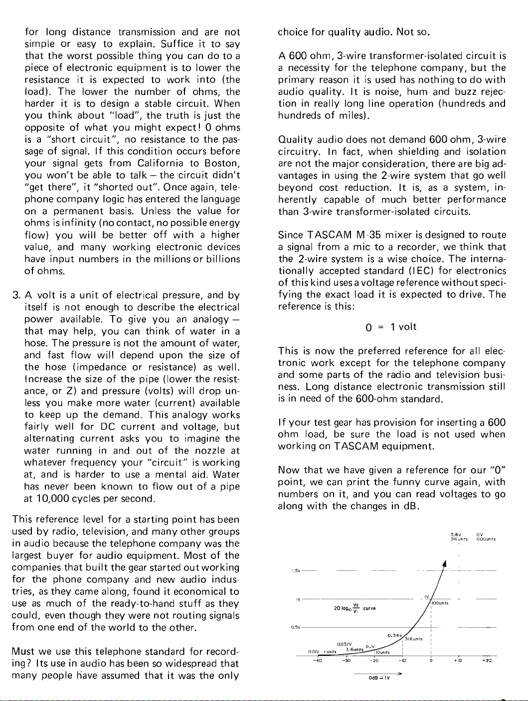
Now that we have given a reference for our "0"
point, we can print the funny curve again, with
numbers on it, and you
can read voltages to go
along with the changes in dB.
,"
20
log,,+
curve
Must we use this
telephone standard for recording? Its use in audio has been so widespread that
many
people tiave assumed that
it
was the only
Page 9
All electronic parts, including cables and nonpowered devices (mics, passive mixers and such),
have impedance, measurable in ohms (symbol
is
or Z). Impedance
presents to the flow of signal, and
to understand some things about this value when
the total opposition a part
it's
important
OUTPUTS
S2
-
plug into
you are making connections in your mixing system. The outputs of circuits
rating and so do inputs. What's good? What
values are best?
signal flow, and in theory,
-
It depends on the direction of
INPUTS
have an impedance
it
looks like this:
It
is
generally said that the output imped-
ance
(Z) should be
ohms, 10 ohms. The lower, the better, in
theory. A circuit with
ance will offer a low resistance to the passage
of signal, and thus will be able to supply
many multiple connections without
in performance or a voltage drop in any part
of the total signal pathway. Low impedance
values
ing transistors and integrated circuits, but
other considerations are
practice, such as:
1. The practical power supply
2.
can be achieved economically by us-
nitely large. At some point, even if the
circuit
ergy you will run out of "juice".
Long before this happens, you may burn
out other parts of the circuit. The output
impedance may be close to the
cally ideal "ohms" but many parts in the
practical circuit are not. Passing energy
through a resistance generates heat and
too much current will
right off the circuit card
taken to prevent catastrophic failure.
is
capable of supplying more en-
as
low as possible. 100
a
low output imped-
still a problem in
is
not infi-
theoreti-
literally burn parts
if steps are not
a
loss
Inputs should have very high impedance
as
high
as
nurnbers,
1
million ohms, more, if
A high resistance to the flow of signal at
first sounds bad, but you are not going to
build the gear.
input will work properly and has no
for a large amount of signal, you can assume
that he means what he says. For you, a
high input impedance isan unalloyed virtue.
It means that the circuit will do
a
minimurn of electrical energy as a beginning. The most "economical" electronic devices in use today have input impedances of
many
ample, voltrneters of good quality must not
draw signal away from what they are
uring, or they will disturb the proper operation of the circuit. A design engineer needs
to
destroying
device to measure with.
millions of ohms, test gear for ex-
see
what is going on in hisdesign without
it,
possible (1 00,000 ohms
it
can be arranged).
If the designer
so he must have an "efficient"
tells
its
job with
you his
need
meas-
3.
Even if the circuit does not destroy itself,
too high a demand for current may
ously affect the quality of the audio. Distortion will rise, frequency response will
suffer, and you will get poor results.
The classic rneasurement for output impedance
load a circuit until the voltage drops 6dB
is to
(to half the
load value is. In theory, you now have a load impedance
ance.
If you reduce the load graudally, the dB
reading will return slowly to
How rnuch drop
left when an acceptable drop
ter!
original power) and note what the
that is the same
is
acceptable? What load will be
as
the output imped-
its
original value.
is
read on the me-
seri-
When the
seven times the output impedance, the
still a little more than 1 dB lower than the original reading.
Most technicians say "1 dB, not bad, that's acceptable". We at TEAC must say wedo not agree.
We think that a seven-to-one ratio of input
to output (1) is not a high enough ratio, and
here's why:
load value (input Z)
is
approxirnately
needle is
(7)
Page 10
1. The measurement
range frequency and does not show true loss
at
the frequency extremes. What about drop
at
20
Hz?
2. All outputs are not measured
Most people don't have twenty meters, we do.
Remember, everybody
you record and the circuit demands, in
are simultaneous. All draw power
tice,
same time.
Because of the widely misunderstood rule of
thumb
you the
Even though the true output impedance may be
low, say 100 ohms, for the practical reasons explained previously, we feel that the 7:1 ratio
not sufficient. To use this rule of thumb, you
must use
"output
model M-35:
ACCESS
-
the seven-to-one ratio - we will give
values for outputs in a complete form.
a
load impedance". For example, in our
SEhID
LINE OUT
higher value. We'll call this value the
is
usually made
at
plays together when
1.4k
ohms X 7 = 10k ohms
1.4k ohms X 7 = 10k ohms
at
a
mid-
the same time.
prac-
at
the
is
level, a loss of headroom, low frequency response,
or
else
suffer from a bad recording. If one input
10,000 ohms, another of the same 10,000 ohms
will give you a total input impedance (load) of
5,000 ohms. To avoid
following when you have two inputs to con-
the
nect to one output.
Take the lowervalue of the two input impedances
and divide
7 times the output impedance, you can con-
still
nect both
not using the true output impedance, we are
ing the adjusted number in group
impedance.
When you
just dividing the
ber of inputs will not be accurate unless they are
al1
the same
(higher than 7 : 1 ratio) by this method, you can
connect without worry.
If you must have exact values, here are the for-
mulae:
it
in half. If the number you have is
at
the same time. Remember, we are
have more than two loads (inputs),
lowest impedance by the num-
size.
For more than 2
calculations you can do
l,
output load
But if you still get a safe load
:
is
us-
is
a
This
the 7:1 method. To go one step further, here are
the actual minimum ohmic
wise. Connect to TOTAL INPUT
LOAD
ACCESS
LINE OUT
Our specifications usually show 10,000 ohms
a
"Nominal Load Impedance" and you can
that we arrived
dividing 10,000 by 7. Any number higher than
10,000
Input impedance
requires only one number.
are'the
MIC IN
I-INE IN
ACCESS RECEIVE 220k ohms
BUSS IN
If one output
puts, the total impedance of the two inputsmust
not
above, and if it becomes necessary to
number of inputs with
load specifications, you must check for a drop in
number that will give good results with
values we feel are
IIVIPEDAIVCE
higher than:
SEhID 10k ohms
10k ohms etc.
as
see
at
the first column above by
is
less load.
is
more straight forward and
Load
is
load, and here
values for the M-35:
600 ohms
50k ohms
12k ohms
is
to be
"Y"
connected to two in-
exceed the load impedance, mentioned
increase the
slight exceeding of the
RX=-j 1 1 1
-+-+-+
R1 R2 R3 Rn
=
RX
For 2 loads or inputs
Finding Impedance Values on Other Brands of
Equipment
When you are reading an output impedance spec-
ification, you will occasionally
statement:
Minimum
Maximum
'rhese two statements are trying to say the same
thing, and can be very confusing. The minimum
load impedance says: please don't make the
NUMBER of ohms you connect to this output
lower than X ohms. That's the lowest IVUM-
any
BER. The second statement changes the logic,
but says the exact same thing.
Value of Total Load
load impedance = X ohms
or
load impedance = X ohms
....
see
this kind of
+--
Page 11
Maximum load impedance refers to the idea of
the
LOAD instead of the number, and says:
please don't make the
do you
lower for ohms. Maximum
ohms, so
When the
you
already
culation. And the number given in ohms does not
have to be multiplied. You can MATCH the value
of your input to this number of ohms
ly;
load).
Occasionally, a manufacturer will want to show
you that
right idea and will give the output impedance
and the correct
output impedance
will give the recommended lowest
pedance.
7
times and will be whatever the specific circu it
in question requires.
increase the load? Make the number
read carefully.
minimum/maximum statement is made,
can safely assume that the manufacturer has
done the "seven times
but
as
always, higher ohms will be okay (less
7
times the output
load this way. They will call the
It
may be a higher or lower ratio than
LOAD any heavier. How
load means minimum
is
best" ratio cal-
successful-
Z
is
not quite the
the true impedance and then
LOAD im-
REFERENCE LEVELS
We should talk about one more reference, a prac-
tical
one.
a
Anyone who hasever watched
around wh ile recording knows that
is not a fixed value of energy.
and can range from "no reading" to "good grief"
in less
you the numbers for gain, headroom and
in the M -35, we must use a steady signal that will
not jump around. We use
and start it out
put, our beginning reference level. All levelsafter
the rnic input will be higher than this, showing
that they
will come to the
line-out and the reference signal there will be
-
louder than 94dB spl, or your rnic will produce
more electricity from
-60dB, al1 these numbers will be changed. We
have set this reference for rnic level fairly low. If
you examine the sound power or sound pressure
musical instruments are louder on the average
than 94dB spl, and most commercial mics will
produce more electricity than the
sound pressure of 94dB, so you should have no
problems getting up of "OVU" on your recorder.
time than
have been amplified, and eventually we
10dB, our "line level" reference.
From this
level
(Spl) chart on page 6 you will see that most
it
takes to blink. In order to give
at
a level of -60dB
last
output of the M-35 - the
you can see that if your sound is
a
sound of 94dB spl than
VU meter bounce
"real sound"
It varies with time
a
tone of 1000 cycles
at
the rnic in-
-
60dB for
noise
a
If you are going to record very loud sounds you
may produce more electrical power from the rnic
than the M-35
you estimate this in advance? Well, the spl chart
and the rnic sensitivity are
to-one basis. If 94dB spl gives - 60dB (1 mV) out,
104dB spl will give you -50dB out, and so forth.
Use the number, on our chart for sound power
together with your rnic sensitivity ratings to find
out how much level, then check that against the
maximum input
the M-35.
or line level, there
it into the
You will
work
!
Most rnic manufacturers give the output of their
mics as
don't give the loudness of the test sound in
it's
a
stated
can handle
levels for the various jacks on
If your rnic
is
nothing wrong with plugging
line level connections on the mixer.
need an adaptor, but after that it will
minus-so-many-dB number, but they
as a pressure reference (usually 10 mi-
as
an input. How can
tied together on a one-
is
in fact producing - 10dB
dB,
Page 12
crobars of pressure). This reference can be found
'
on our sound chart. It
10
dynes per cm2 or 1 Newton per square meter.
For mics, the reference
is
the sound
the rnic
94dB spl, the electrical output of
is
given
is
94dB spl, 10 microbars,
"0"
is 1 volt (dB). So, if
as
-60dB, meaning so many dB
less than the reference 0=1 volt. In practice, you
will see
up to about
levels of -60dB for low level dynamics,
-40dB
or slightly higher for the
better grade of condenser mics available today.
TASCAM recorders and mixers work
-10dB referenced to 1 volt (0.3 volt) so, for
of
94dB spl,
will
a
rnic with a reference output of - 60dB
need 50dB of amplification from your M-35
or recorder in order to see "OVU"
your meter. Now, if the sound you want to re-
is
cord
/
the rnic will be more powerful and you will need
louder than 94dB spl, the output from
less amplification from your IVI-35 to make the
needles on your recorder
read "OVU".
at
(-
l
OdB) on
a
level
segments.
1. As laid out for
2. As wired, but knobs and jacks
convenience.
as
they appear
on the outside.
3. The block diagram, with the controls
bered
to correspond to numbers on the first
num-
two drawings.
Even with this "translation system" to help, multiple sources and outputs
so when necessary; we will
types of drawings to help get the point of
can complicate things,
also include other
a
sub-
system across when we first encounter a source
a
"point" that will be used in
may
require re-reading if you are not familiar
with subsystems, but we think
you
as
early
as
possible.
specific way. This
it
best to advise
THE
BLOCK
DIAGRAM AND GAIN
DI AG RAM
'
Before you begin reading the next section of this
manual, flip out the extra fold on page 42. On
this page, we
have printed the block diagram. It
shows the signal flow through the M-35 and
represents in simple form, the actual electron
al1
arrangement of
stages from
mic-in to line-out.
the jacks, controls and gain
The diagram on page 43 indicates the gain of
"
reference signal, the noise level, and the available
at
reserve gain or headroom
any point in the
signal chain. An experienced audio engineer
would be able to operate the M -35 successfully
a
with just these two diagrams and
list
and output specifications.
Any question about function or gain
swered by studying the drawings. Will the accessory send signal change in level if the input fader
is
moved? No, the signal
is
shown leaving the
main line before the input fader. You read both
diqgrams from left to right, input to output.
BLOCK
it
a
of input
can be an-
When printed in
its
entirety, a block diagram can
look formidable, and tracing a signal path
easy, so to aid you in your initial understanding,
/
we'll continue to use our 3 drawing system first
shown in the introduction, but in slightly smaller
d
is
not
Page 13

INPUT
MODULE
6
Q
Input Select
Trirn
@
LINE
n
@
All 8 input modules are identica1 and can be in-
terchanged without modification.
Mic input
Balanced pad circuit contro1 MIC
3 positions are provided: off, or no effect, set
rightwards one step, a loss in signal of
rightwards two steps,
Before using the first step, reduce the 8 trim
contro1 to minimum or furthest countercIockwise
rotation. Since the combination of trim and pad
is a maximum of 60
this mic-in jack
tools are available to convert a 3-wire circuit to
2-wire RCA connector - if the line level signal
can be reduced to a max of OdB, (1 V).
XLR
connector
as
@
ATT
switch
20dB, set
a
loss in signal of 40dB.
dB loss,
an emergency "line in" if no
it
is
possible to use
a
a
XLR
frorn Subrnaster Tape
Input transformer
Maximum signal to this internally mounted transformer
or MIC ATT switch. At 20dB pad, maximum
put is -15dB (17.8mV). At 40dB pad, maximum i'nput
This 3-pin connector, pad circuit, and transformer
are the only 3-wire circuits in the M-35.
We
ing a better way to do the audio job, and rnic
lines do not run for "miles and miles" in our sys-
tem. Why do we use this more expensive design
to begin with if
ity? The low-power signal that the rnic generates
must be protected and isolated from other
is
-35dB (17.8mV) without using the pad
have tal ked a lot about the 2-wire circuit be-
@
is
+5dB (1.8V).
it
offers no improvement in qual-
in'
*
in-
low-
Page 14

power signals in the real world. Radio power line
hum, crackles and switching noise when motors
start up (do you
line?)-al1 these unwanted things-must be kept
out of the very high gain amplifiers that are
cessary to raise the rnic signal to a working level.
So, the balanced or 3-wire, circuit and input-isolation transformer becomes the only cure way to
dea1 with the problem:
Here's how it works:
Mic
Any signal will pass to amplifier, no rejection.
Radio Frequency I nterference
Mic
have a refrigerator on your AC
ne-
7~--
m
Audio signals from rnic have opposite polarity.
Buzz, hum, and
Signals with opposite polarity in the primary coi1
will genera1 current in the secondary coil. Signals
with common polarity will cancel out in the
mary coi1 and will not pass to the secondary coil.
No signal in the secondary
in the amplifier.
RFI
have common polarity.
rv Secondarv
/=%;j'lL-i
RF cancels in transformer
coi1 means no signal
pri-
Right here we
comprehension. The connection and
is
drawn plainly on the block diagram, but what
does
it
mean in functional terms? Why
PUT switch wired to this extra LINE IN when
there
is
another LINE-IN on the module? The
answer
tem in use, and to explain, we'll have to show
the system in
not reviewed the first path to the recorder
We must assume that a recorder has only one set
of playback outputs. We will
basic jobs to do that
1.
2.
3.
Three tasks, one output. How do you plug in?
This
module, not the input module, and the
tions are laid out on the back like this, part of
our standard "working patch" for 8-track
ing.
lies in the requirements of an 8-track sys-
Simple playback to judge performance, requir-
ing no corrective EQ. In short, what did you
record
Simple playback into a cueing system so partially
function should somehow combine the signals
of
musicians may hear when overdubbing.
Final remix, when the full contro1 capability
of the system
used to "fine
?
completed tapes can be finished. This
simple playback with new rnic signals, so
special input RCA Jack is on the master
have our first major problem in
its circuit
is
the IN-
its
entirely, even though we have
at
all.
have at least three
require the playback signal:
(EQ effects mixing, etc.) can be
tune" the finished tape.
8
sections
record-
Input Select Switch
This switch has 3 positions. Left selects the IMIC-
IN XLR. Right selects the LINE IN RCA jack on
the back of the module, and center selects one
of the TAPE IN jacks on the buss master mod-
ules. Since each input module will receive only
one TAPE IN signal, we'll
show which signal goes to which module.
provide a chart to
Page 15

The numbers on the input module now relate to
the jacks on the submaster. Track one from tape
playback will now be available on three separate
systems. If only the "line input" on the input
is
module
used, the signal will only be available
for "re-mix" and
al1 module settings for "mic"
will have to be disturbed - every time you playback. By using the TAPE-IN jack, resetting
is
avoided. Another drawing may rnake the wiring
more understandable.
for contro1 roorn
M-&\
Track 8 playback
To keep the routing clear, we show only the last
submaster module that handles track 8 and track
4.
The other groups are similar, routing signal to
EXPANDER INPUT
EFFECTS RCV
EFFECTS RCV
EFFECTS RCV
EFFECTS RCV
I
2
3
4
their respective input module numbers
as
shown
in our first drawing (the one with the 8-track).
TAPE
IN
11-41
CUE OUT
Il
Il
EFFECTS SENO
1x11
TAPE IN
15-81
AUX IN
L
R
L
CONTROL
R
STUDIO FEED
L
STUDIO FEEO
IREAR1
STUDIO FEEO
TALK BACK
RDOM
l
n1
Page 16

Now for the three requirements of tape playback:
1.
Simple record check
To do this, the tape playback signal
tuted for the monitor output signal on the
submaster monitor select, and the monitor
mix
is
now derived from tape playback on each
section so switched. Any or
is
substi-
al1 8 may be
selected individually and the
master
room loudspeakers.
will then set a level for the control
control room
Page 17

-
-Q
T-.,
u*
z
.-
I'
i
i
2.
Cue System
Tape playback plus
LINE
IN
1.81
RCY
EFFECTS
EFFECTS RCV
EFFECTS RCV 4
;A
@
2
3
-0
.
:-
7
I,
o
i'
I
mic cueing for overdubs.
7.
,Lo~nan
"i,
.-v:...
Q
,llllllll~'
l l
l.l l l
l
l
,
11
*oirin.""-o
t
81155 IN
(.41
OUT
LUNE
(x41
nux OUT
1x4)
TAPE IN
1141
CUE
OUT
1x1)
EFFECTS SENO
1111
TAPE IN
15-81
t,
'
From
Tape 4 Tracks
This cue system combines the tape playback con- "hear"
trols
(x8) on the submaster modules with the input cue controls (x8) on the input modules to
form a mono sum of al1
16
possible signals that
buss allows you to set levels; but caution is advised. The headphones volume may not
directly to your
it,
and a meter shared with the effects
contro1 room volume. You have
might be needed for a musicians cue. Since the a master for loudspeakers, but
monitor system for the
contro1 room can be set
to audition this signal "mix" you
will be able to
this mix in the headphones. The
master pot.
relate
it
does not affect
cue mix has no
Page 18

3.
Tape-in for Rough Remix
MIC IN
1x01
EFFECTS RCV
EFFECTS RCV
EFFECTS RCV
EFFECTS RCV
I
2
3
4
EXPANDER INPUT
AUX OUT
1x41
TAPE l N
11-41
CUE OUT
11 Il
EFFECTS SEND
111 I
TAPE IN
15-81
When the INPUT select switches on the modules
are set to the center position, the
submaster
TAPE IN jacks are internally connected to the
input modules. Selecting this remix position on
the input module will not disable the
norma1
operation of the monitor. Signal will go to both
circuits
at
the same time, allowing separate use
of the monitor outputs as extra mixes. True
stereo echo is an obvious first choice, and the
mixdown
AUX IN position on the
module.
one module
machine can be monitored using the
contro1 room monitor
Since the remix position can be selected
at
a
time, a single track may be
equalized and monitored without disturbing
mix
to
2
track
MIC
IN settings on the whole mix. A decision
can be made quickly on the artistic success or
failure of an
individua1 part without the need to
place the entire console in remix mode just to
see the effect of corrective equalization on
single track. Since the TAPE IN jacks on the
buss master moduels actually feeds 3 separate
it
mixing positions
load to anything connected to
on the module. TAPE
will present a more severe
it
than "Line in"
IN'S have an input load
impedance of 20k ohms and LINE IN'S (on the
input module)
have an input impedance of 50k
ohms.
a
Page 19

Line In Jack
An RCA jack on the rear of each input module.
The maximum signal you can apply here
+15dB. The MIC ATT switch does not affect
this input. The input impedance 50k ohms.
Trim
control will alter the gain of the first ampli-
This
fier in the console. It will affect the level of any
signal, M IC, LI NE or TAPE. With this pot rotated
fully clockwise (rightward), the maximum gain
of the first
the maximum input
-
1 l dB (282mV). When the pot is in
amplifier is 26dB.
signal before overload is
In this position,
its
minimum setting (fully counterclockwiseor leftward)
the gain
is
reduced to 5dB and the maximum
signal that can be handled without overload will
be +10dB (3.2 V). Remember, these overload
figures refer to the input of the amplifier, not
the input
pads
plug or connector. Losses occur, and
can be inserted before this point. The
maximum signal that can be applied to the LINE
IN jack is +8dB (2.5 V) with the TRIM rotated
fully leftwards, and +30dB (31.6 V) with the
TRIM rotated
the gain of an amplifier by adjusting the
trol
amount of output
input
reverse
control "pot" or input. Because of this
control aspect, we consider it unwise to
adjust the TRIM
Obviously, you must adjust when signal
but when serious recording
fully rightwards. Trim pots con-
signal returned to a secondary
while signal
is
being recorded.
is
present,
is
in progress the
possible negative side effects on amplifier stability and distortion indicate that you should "mix"
with the straight
master faders
line input, submaster, and
P
only, and adjust "trim" during re-
hearsal.
Cue Pot
At this point in our input module, we derive signal
for a or headphones mix. This function
a
is best served by
constant after being set, so
mix of signals that will remain
it
is
drawn off, before the input fader. To raise the level, rotate
rightwards or
clockwise.
This pre-fader source insures that your mixing
decisions
the studio. The
will not interfere with the rehearsal in
only thing that
is
more annoying
is
to a player wearing a headphones than a sudden
change in tone
instrument
tion is in large part a response to what
and if the
is
losing track of the sound of his
entirely. Remember, al1 music execu-
is
heard,
main source of sound is provided by
this headphones "mix", and you turn it off in the
course of some other
control room action, you
will deprive the player of the creative guide to
what
is
going on. Your session may stop cold
right then. 'rhe cue system routing has been
drawn on page 18 and shows the 16 sources of
signal and the inputs and outputs on the back
panel.
Overload LED
When signals high enough to make the ACCESS
SEND jack output
an input
module, this LED will light up. The
exceed
TRIM, or the MIC ATT pad
+l
5dB are applied to
should be adjusted
until the LED remains out when signal ispresent.
When recording
extremely percussive transient
material, it may require full negative trim and
pad (MIC ATT) to prevent this LED from
flicker-
ing on strong peaks. Changing to a less-sensitive
may help.
rnic
Access Send - Rcv Jacks
The high gain provided by the rnic preamplifier
allows
useful position. The level at the
-10dB (0.3V) and the output load impedance
us to place a "patch-point" in this more
SEND
jacks
is
is
10k ohms. A limiter connected to this point in
the M-35 circuit
compression that
the
equalizer (next stage) is adjusted or the input
fader
is
moved (the stage after the E0 amps).
This pair of jacks is not
device
is
bridged from SEND to RCV, jumpers
must be in
can now be set to a range of
will not be altered when either
"normalled" so, when no
place for signal to flow to the E0
amps and on through the console. However, since
al1
the mixing controls lie after the "RCV" jack,
it
is
possible to use "ACCESS RCV" as an input,
and by-pass the first gain stage. The only
func-
tions that will be lost are the trim and overload
indicators. The signal quality will improve slightly
but
it
will not be possible to switch to "MIC
IIV", "LINE IN" or "TAPE" without repatching.
is
This unorthodox patch
suggested for final re-
mix when al1 recording has been completed, and
more
time for patching
level in will be +15dB. Input impedance
is
available. Maximum
is
220 k ohms.
Page 20

PARAMETRIC EOUALIZER SECTION
Before we begin, the label itself will requiresome
explanation. What
what
?
A logical quest ion, because the term does
is
parametric and, equal to
not describe what you do with the controls. In
multitrack audio, tone controls are almost
always
used to "make different" and the concept of
"make the
get this
The telephone companyuses
same" doesn't quite fit. How did we
label on our tone control?
it.
In the earlydays,
the system worked well in the lab, and in short
runs of 100 yards or so, but
. . .
. .
When two "phones" were 10 miles apart the line
between them did not transmit al1 of the sound
representing signal in the
same way. Some parts
of the frequency spectrum did not pass down
the
line at all, some parts were different in level
or displaced in "time". What came out of the ear-
was definitely not what had "gone in" 10
piece
miles away and understanding
proved to be difficult. What now?
a
conversation
'rhe Phone
company had to learn how to make the output
"sound like" the input.
If "output equals input"
is
the concept, an "equal-
izer" is a logical name for the device used to fix
your problem. Just as in many other concepts in
audio, the telephone company language has set
the terms we use today.
The term "parametric" refers to the
adjustable
frequency point. The "parameters" or "rules" are
not fixed at any given number, but are
ously
variable. Both aspects of the circuit, fre-
continu-
quency center point as well as gain or loss are
continuously
are
limits.
The
Model 35 offers a two control, four range
adjustable without "steps" but there
parametric equalizer. The lower group of controls
offer
+10dB of boostlcut control at any frequency between 60Hz and 1.6kHz in two ranges,
selected by the switch below the concentric
controls. Set leftwards, the switch selects the range
from 60 to
fully leftwards or counterclockwise then sets
center frequency of 60Hz. As the outer knob
300Hz. The outer knob when see
3
is
rotated rightwards (or clockwise), the center frequency
right (or clockwise), the center frequency
is
raised in stepless fashion. When fully
is
300Hz. The inner knobT the boostlcut control.
Set fully leftwards, the cut
rightwards, the boost
is
is -10dB. Set fully
+
10dB.
When the lower switch
the action
is
the same, but the range changes.
Outside Control,
rotate right to
raise center frequency.
Inner Control
rotate leftwards to cut
rotate rightwards
toWboost"
is
set fully rightwards,
Page 21

The upper group of controls offer
or cut
at
any frequency between 1.6kHz and
il
OdB of boost
is
As the outer knob
rotated rightwards or clock-
wise, the center frequency
is
raised in stepless
15kHz in two ranges, selected by the switch be- fashion. When fully right, or clockwise,
low the concentric controls. Set leftwards, the
switch selects the range from 1.6 to 5kHz. The
outer
knob when set fully leftwards or counter-
clockwise then sets a center frequency of l .6kHz.(p
-P-
center frequency
The inner knob
ly
leftwards, the cut
wards, the boost
is
5 kHz.
is
the boostlcut control. Set ful-
is - 10dB. Set fully right-
is + 10dB.
&g
When the upper switch
is
set fully rightwards the
range once again, is shifted upwards.
i)
oci--
IL-
The center position on both upper and lower frequency select switches
is
"off".
The great advantage of
a
"parametric" or con-
tinuously "tunable" equalizer over the more con-
is
ventional "set" types
that you can tune your
frequency center point to the precise area you
need, and then cut or boost will have the rnaxirnum desired effect on your art. You get the result you want with rnuch less rotation of they
boostlcut
control, and put less "strain" on your
electronics. No matter how many "frequencies"
there are on
that anyone
"set" type equalizer,
will be "just right" and many more
it
is
unlikely
a
ranges are needed to do the job. In the long run
a
"parametric" type requires fewer parts to do
the job so
it
costs less, and perforrns better than
Page 22

"graphic equalizers" which rnay leave rnany sections unused on a given input, or "set frequency
select" types which never seern to have the right
"nurnber"
in
electronics
using the tone controls on rnic
to get as
the rnic. Even a
rnake a big difference in the sound quality. Listen
to the sound frorn the
your head where the rnic is, and listen carefully.
What do you really hear? Is
Doing this check rnay
Too rnuch bass? Not enough? Well, perhaps there
is
a
better location for the rnic in order to get the
balance you need. When you have gone as far
you can in this fashion, the tone controls will get
you the rest of the way.
However, the "ear test" rnay not be wise, if the
volume of sound
head near to any part of a drum set. Even if
moderate force
rnic
to cause perrnanent darnage to your ears.
available. "Less"
is
alwaysthe safest route, so before
close to the sound you want by moving
srnall change in rnic location can
as
a working concept
signals,
actual rnic position. Place
it
what you want?
help solve rnany problerns.
it
is
better
as
is
very high. Don't put your
only
is
used to play drurns, at close
distance, the sound power rnay be enough
For a steady tone frorn an organ or a violin, this
rnight be just enough to avoid
it
is
distortion, but
with any percussive peaks frorn things
guitar or drurns.
Even experienced engineers
forget that "cutting" the
effect to "boosting" the highs, and is much easier
on the
and
sults
rant trying. Cut bass, raise the overall gain, and
see if it sounds better than
highs.
electronics (cutting leaves more headroom
consequently causes less distortion). The re-
are not identica1 but close enough to war-
definitely not enough to cope
clipping, or serious
like piano,
have a tendency to
lows will have a sirnilar
sirnply boosting the
If you have the timeand a co-operative rnusician,
experirnent with different combinations of rnic
placement and tone control settings. Although
can be very tiring for sorneone to play a part over
and over again
best way to get the knowledge of rnic technique
tonal balance you need to rnake good rnixes.
and
In fact, experience
work on your specific problern, i.e., your guitar,
your
voice, your rnusic. All the inforrnation we
can give you in the rnanual will only be a starting
point. How far you get
On the
that the tone
(IIOdB) and a very largeexcessgain capability or
"headroom"
the assumption that the tone
the
serve in the circuit is necessary to rnaintain a 20
dB value of "headroom" when the tone controls
are set for maxirnurn effect. Without this extra
rnargin, you
the input fader when you used the extrerne boost
or cut settings of the tone
block diagram and gain chart you can see
"flat" or "no boost or cut" position. The re-
while you "go to school", it's the
is
the only teacher that will
will be up to you.
control stage has a moderate gain
(25dB). This gain chart isrnade with
controls are set to
would have to lower the setting of
controls.
it
it
Add
25dB and you boost
kHz, your margin of safety
up - if you start with a reserve of only
+l
0dB (the rnaximurn) at 10
is
reduced to 15dB.
Page 23

I
npu
t
Fader
Controls the signal level from
Faders,
cause loss in order to
stages in an electronic
open"
they
also called pots or attenuators always
control signal level. Gain
device always run "wide
at
whatever gain they are set for, unless
have provisions for "TR IM" or actual gain
al1 prior stages.
adjustment. In the M-35 only one of the many
amplifiers employed
first gain stage or
advance any straight
are just reducing the loss
signal flows to the next stage only if the fader
"wide open", or up
actually has "Trim", the
mic preamplifire. When you
line fader on the M-35 you
it
causes. 'the entire
is
al1
the way.
Effects Send Pot
is
This rotary control
the preferred location to
use when a secondary "mix" must reflect the
prior mix decisions of level and equalization.
is
a
"Echo Send"
good example of such use and
this post-fader, post-equalizer signal will then
also "fade out" as you "fade out" the regular
signal with the input fader.
Eight signals, one from each
module can be combined, and metered and will appear on the backpanel output jack marked "EFFECTS SEND".
On the M-35, this mix cannot be monitored
separate1 y until
the effects
trol on
its
it
is
returned
aftft
processing by
device. This send has no master con-
output.
EFFECTS
RCV
EXPANOER
INPUT
4
A
"buss in" or piggyback,
is
provided toallowadding more such "effects" signal from an expender
or another mixer. "Effects Return" lines will be
but
no master,
and no separate monitor.
drawn later when we get to the submaster modules.
Page 24

Direct Out Switch
When depressed,
rect out jack on the back of the input rnodule.
Push to lock, push again to release.
Direct Out Jack
Provides an unmixed single signal output of
ever has been assigned to the module. This direct
output
as:
1.
2.
can be used for a variety of purpose, such
A subsidiary mix can be made by using an ac-
cessory mixer fed by this output.
One-rnic, one-track recording happens frequently, and using DI RECT OUT will pass unneeded
ing "Direct" to the recorder will result in a
cleaner signal.
sumrning networks and amplifiers. Go-
allows signal to pass to the di-
what-
8
track monitor
Channel Assign and Pan Pot
On the M-35 rnonitoring will be possible by
switching the appropriate monitor section to
"TAPE" and listening to the recorder instead of
a buss rnaster. For metering, either the recorder
or an accessory meter bridge (MB-20)
Since the amplifier that feeds this jack also feeds
the buss-assign network and the post fader effects
system
fully. The
10k ohrns. The load of the pre-wired circuits restrict the connection of this output to a single
circuit at a
on connecting here
values for input irnpedance
it is wise to calculate the total load care-
output load impedance of this jack
time, unless the equipment you plan
is
known to have a very high
(100
can be used.
k
ohms or more).
is
Stereo monitor
no monitor yet, so
monitor playback
out electronics with
switchable buss/tape monitor
M-35
Page 25

Solo System
This rnomentary pushbutton will divert input
rnodule signal directly to the monitor section, replacing the subrnaster monitor rnix with a single
signal. Although these switches do not latch,
more than one may bedepressed sirnultaneously,
providing a mix of those buttons "held". The
nal "rnix" in the monitor
This location as
rnodule will
a
source for signal on the input
allow auditioning
is
"center feed rnono".
EQ,
but the input
sig-
fader rnust be advanced for the signal to flow.
Since no "return type solo" is provided on the
submaster rnodules, effects-returns will be rnuted
as well as monitor when any solo
is
held down.
Since this entire systern affects only the monitor
output (not the direct out or the master
bussouts or any other minor as well as rnajor output),
al1 recording will continue unaffected while this
solo system
is
in use.
The channel-assign switches and the pan control
together make up the last section of the input
strip. At this point you
has appeared at the direct-out jack,
been set with the input fader and you
the necessary changes in
What rnaster
"line out" do you want
have selected a signal,
its
level has
have made
its
tonal quality.
it
to go to?
it
Line one, line two, line three, line four - any or
al1 may be selected by depressing the appropriate
buttons on the channel-assign strip. Push to lock,
push again to release.
Depressing more than one button will engage the
"Pan" control. This single knob works two faders
that are wired "back to back". As you rotate the
knob, one fader
ed down. When the control
fader
is
still
is
turned up as the other
is
"dead center" each
is
turn-
reducing the signal slightly so that
the signal transition through "center" does not
becorne louder as you "PAIV" through
it.
When
both speakers in a stereo pair are producing
sound, you don't
tain a constant volume. If only one button
need as rnuch power to main-
is
depressed, the pan control has no effect on the
signal. When any two buttons are depressed, the
lower number
control
is
wise. The higher
is
"Panned" to full on when the
turned as far as
is
"Panned" tofull on clockwise.
it
will go counterclock-
The "PAIV" logic for
or 4 button arrays
is
3
easiest to explain with some drawings. If shaded
buttons are assurned to be down, the logic is:
Typical examples
of
multichannel panning
Summing Amplifier
Leaving the Pan/channel assign, the signal
ed through a "surnrning
drop in level before
the surnrning
arnplifier. This loss
resister"
it
is
and suffers a big
allowed to pass down
is
is
pass-
necessary to
prevent the signal frorn one input going back into
another instead of going down the
master fader. You
can think of the surnrning re-
line to the
sistor as the "traffic cop" that turns the line into
the "one way street" you
Buss In
Jack
need here.
The prirnary purpose of this final input on the
block diagrarn
is
to 'StackMor run a pair of rnixers
with one overall rnaster control. The input irnpedance
and signal point are identica1 to the accessory receive jack. Any electronic device that
has a cornpatible output irnpedance rnay be connected here and
its
contribution to your rnix will
then be controlled by the subrnaster fader on the
M-35.
Page 26

SUBMASTER MODULE
Effects receive to "buss" function actually comes
first only if the latching pass switch
by the rule of "wiring first"
we'll pick up the sys-
tem now, and mention that we will see
is
down, but
it
again
in the monitor section.
Effects Rcv Jack
An RCA connector on the back panel of the
submaster module intended as line level input to
either the summing amp
(Buss) or the monitor
section signal route, depending on the position
of the
mon/pgm switch.
Effects Rcv Pot
This rotary control adjusts the signal received
from the RCA effects-receive jack.
Mon/Pgm Push Switch
When depressed, signal from the effects RCA
Jack
is
assigned to the buss summing amplifier.
Master Fader
(4
This four-ganged
Section) pot provides final
level control of al1 four output sections of the
mixer. This signal control operates
at once. Any signal added to a buss from the
ous jacks on the M-35 will be affected by the
ting of this control, if your mixed signal
al1 four faders
vari-
set-
is
taken
from the last output pair on the block diagram.
Meter Drives and Meters
Two lines are shown on the block diagram here:
one to the monitor circuits, one to the meter
circuits. We'll go "up" on the block first, and dea1
with the visual references, the meters and peak
LED. These two circuits
ly,
and will respond as set. .Original setting for
the LED
ampl
is
can be adjusted internal-
OdB above 1 volts. Original
setting for the meter is OVU = -10dB.
Pad Switch
On the back panel of each submaster module,
this switch when set rightwards (when you are
facing the rear panel) will lower the
(0.3V),
output to -10dB in order to match the
inputs of most TASCAM recorders. When
-2.2dB
set
left-
wards, the output will be higher. There is no
need to adjust the meters because they follow the
signal at "high"
be
visually correct for either setting.
al1 the time, so the "zero" will
When raised, signal from the effects RCA jack
assigned to the monitor system only. You can
hear
it,
but
it
won't "record".
Let's leave the monitor system and
its
multiple
functions for a while and return to finish our
"main line" out.
Su bmaster Fader
This fader controls the overall level of
signals
from the input modules and the effects receive
section, when effects are selected.
is
Line Out - Aux Out
One last gain stage appears after the master fader
and just before this double output jack. A
amount of gain
is
necessary to make up the loses
small
caused by wiring up the master fader, and to give
a
a solid source of signal with
ly
low output impedance to whatever you are
mixing to. The
on the setting of the
final reference level
high/low switch on the back
stable and relative-
is
dependent
of the submaster modules.
O
=
Either -2.2dB (0.78V) High
O
=
Or -10dB (0.3V) Low
Since the two output jacks are connected to the
same gain stage, any device connected to one pin
will affect the output capability of the other pin.
To determine the true value of loading on the
mixers
final stage, the input independence values
of both devices must be considered even when
only one of them
is
being used. For this reason
Page 27

we suggest that you unplug anything connected
to the
make your most
pedance
final stage that you are not using when you
critica1 mixes. The output im-
of this stage
is
100
ohms.
It's
always a good idea to use
of electronic stages
a circuit for
as
you can. If you don't need
its
control or function, bypass
and your sound will improve.
as
small an amount
it
At this point in the circuit we
Buss Master Mix.
All functions of the input mod-
have a complete
ule will affect the signal here, al1 majorand minor
patch points are behind us, and
corder
-
is
concerned, the signal
we are done. The only problem remaining is:
as
far as the re-
is
ready to record
how do we hear what we are doing? This signal
must go to our monitor circuits.
Monitor Section Function
The block diagram shows the controls that in-
fluente
the monitor signal as a "one module" layout, but al1 four submaster modules have slightly
different labels to account for the TAPE IN jacks
and their relationship to the input modules. To
make functions more understandable,
we'll show
the ent ire top panel as it appears on "the outside".
Several aspects of
control require the entire sec-
tion, and the top panel will help.
Buss as Source (Diagram)
There are two switches that seem to do the
same
job, feeding signals to the monitor system. This
apparent doubling of function
is
provided for
severa1 reasons. Even though the M-35 has only
four buss master modules,
it
has an 8-track monitor system. Setting the monitor select switch to
the left selects "buss master output" as a signal.
Resetting to the right-most position will now
as
select "Tape"
positions to monitor the playback of
Because of this 8-track monitor requirement,
a monitor, and we need eight
al1 8 tracks.
al1
monitor controls are doubled and there are two
apparently identical sets of controls. When used
as
"Buss Master" monitor, they become redundant, but the two sections are not identical in
"Tape" mode. Monitor section "A"
is
connected
only to TAPE IN A, and monitor section "B"
toTAPE IN B.
only
Page 28

Tape as Source
If our basic 8 track setup on Page
will get
monitor or Buss Master Module (one for each).
Upper tape select will be track
will be track
buss master
Monitor Select Switches. However, this switch
does not
the Tape circuits immediately above, it only
works on the rotary fader marked "Mon Gain".
a
different track on each section of the
5.
Both monitor section will see
1
when Buss Out
control the logic of signal selection for
33
is
used, you
1,
lower tape select
is
selected by their
Monitor
This dual concentric pot (one inside the other)
controls both the level and the monitor pan.
inner section
pan.
or
vidually
Monitor Pan
The Monitor Pan affects only the monitor mix.
It will not alter the level or pan position on the
Buss Master output when input panning
between two busses; but, if both selected busses
are monitor-panned to the
reo monitor mix, turning the input pan
will produce no audible result. Input panning
will, in fact, affect what you record, but you
won't
unless the "Monitor Pan" on the two busses are
set one to each side. This fact
of trouble. Work through this part of the block
diagram carefully, it
take sometime to understand thoroughly.
GainIPan
is
the gain, the outer section
8
sections are provided for 8-track playback
4
buss output monitor. Each section
switchable to Buss or Tape.
same side in your ste-
have any indication of what you are doing
can give you a lot
is
very complex, and can
The
is
the
is
indi-
is
done
control
Page 29

EFFECTS RCV
This group of controls enters the monitor
the same point
switch, but
to
its
center position, the Effects return signal
will be
al1
Group
at
as
the BussITape monitor select
slightly before
it.
If the switch
is
set
that remains in the monitor, and you
will be able to hear "effects only". This signal
enters the system prior to "pan" so effects signal
as
will appear in stereo
on the monitor section. The
button group
input Jack
the right
switch
is
can be made to receive signal from
#l
by setting a back panel switch to
(as
you face the rear of the M-35) the
on the Master Module in line with the
affected by the pan pot
entire four pot and
level HiILow switches, set leftwards, each effects
receive section
its
own effects in Jack.
Set rightwards, module
feeds
al1 four sections internally with the same
is
routed to
its
own module via
1
effects receive Jack
signal.
NORMAL
NORMAL
BUSS
BUSS
l
1
Page 30

MASTER/MONITOR MODULE
Master Fader
This four-section slide pot appears here physically
but the outputs
vidually
on the submaster modules.
Solo Level
This rotary pot controls the level of the solo
system when a Solo signal replaces the regular
monitor signal. Check this before you depress
"Solo" or the setting may be to high or low.
Control Room Group
This rotary pot and switch controls gain, and
selects signal for the control room outputs on
the back panel. The switch has three sources.
1. Set leftwards
Selects the monitor eight-group gain and pan
as source.
it
actually controls appear indi-
7
2.
Set "Center"
2. Set "Center"
The signal source becomes the Cue 16
mixer.
3. Set rightwards the monitor signal source
comes the signal present at thelRUX IN" Jacks
on the rear of the master module they appear
line" with the buss-outlaux-out jacks.
in
X-1
be-
Outputs for the control room group signal are
marked "CONTROL ROOM". Output level
-2.2dB (0.8V).
Max output before clipping
is
+18dB (7.9V).
Auxiliary Line I n Jacks
A stereo pair provided to allow the monitoring
of a 2-track recorder or other subsidiary without
the necessity of disrupting assignments or patches
elsewhere on the M-35. These Jacks
also feed the
adjoining Studio Monitor Pot.
"Studio" Control Group
This group is identical to the control room group
in
its
sources of signal and logic.
duplicate identical in
al1 ways except one. Solo,
It
provides a
when depressed, will not appear on this output,
it
will still carry the "mix" you have selected.
Output level is
-2.2dB (0.78V)
Max output before clipping is 27dB (22.4V)
Cue Out Jack
Shown earlier, this Jack carries the 16 X 1 (mono)
output of the Cue system.
Effects Send Jack
Also discussed, this Jack carries the 8 X 1 (Mono)
output of the effects-send Pots on the input
modules.
Page 31

Cue in Expander Jack
8
X
X
This jack, allows you to add signals to the 16
cue mix. Level control will be necessary from
your accessory.
Effects in Expander Jack
This jack allows you to add signals to the
effects output. Again,
control on this input, level control "outboard"
will be required.
since there
is
no separate
TALKBACK MODULE CONTROLS
1
1
Front Panel Headphone Jack
This standard ring-sleeve-tip (3) wire connector
for stereo headphones
This jack is driven by
IVlax power into 8 ohms
What signal appears here is controlled by..
Headphone Select Switch
Selects either the control room group (set left)
or the studio group (set right).
can be connected here.
a
headphone amp.
is
100mW.
. . .
AND RELATED OUTPUTS
Talkback Mic
A built-in condenser microphone will allow you
to "talk" to 3-circuits on the M-35.
The Cue Buss
A level control
switch will enable the circuit.
The Studio Output Group
The lowest pot sets the
switch enables the circuit.
"Slate"
This push switch is in the center and
volume control will apply talkback signal to
four output masters simultaneously, allowing you
to
verbally identify a tape (what take, what tune,
etc.)
Slate Tone
If this switch is set rightwards, a 60
be added to the slate push switch and pot. When
re-winding
as
medium pitch "chirps". If you count them, you
will have a guide
having to slow down and "play" the tape.
Talkback
This 2-wire jack
talkback
amp and single speaker to your studio, and use
the studio group for some other purpose.
at
rnic signal if you wish to run a separate
is
provided, and the top push
rnic level, the lowest push
its
related
al1
Hz
tone will
high speed, slate tones can be heard
as
to where you are without
is
provided to give access to the
Headphone Level
For control of headphone volume.
Solo Expander Coupling Jack
This three-wire ring-sleeve-tip circuit couples the
solo function between the M-35 and the M-35
Expander Frame.
solos together. Be
use
is
wired this way.
The two remaining controls on the M-35 are on
the meter panel.
Power Switch
Enables AC,
tion
is
30 watts.
NOTE: See page
note for U.
Meter
#5
Select Switch
This extra meter
output level of either the
mix. Set CUE for
fects send.
It will not couple two M-35
sure the connecting cable you
"Solo"
cable
120V,
GCIHz,
44
K.
can be switched to show the
cue mix, set EFFECTS for ef-
IVlax. power consump-
for voltage conversion and
Customers.
cue mix or the effects
Page 32

STANDARD PATCHES AND SET-UP ADVICE
The standard patching setups described here are
not rigid commands. Rather, they are provided
with the hope that they will stimulate your
agination when you have mixing needs that cannot be solved with the standard setup. Line level
line level, whatever the source, and many line-
is
level inputs to the M -35 offer a route to a mix
that will be used for
is
one that
on the back are there to be used. Patching
a crime and may be used to improve the quality
of your signal by bypassing
or by making additional
orthodox ways.
Most
of connections when they set up
it
and
just on the top of the mixer takes some
become familier with, but multichannel record-
ing has many mixing
patch
affraid to re-plug. There is nothing wrong with
the concept.
of each mode of operation and re-patch the M-35
to suit, you
For this reason, we suggest that
cess to the back panel of the mixer. Don't set up
the system in such
mess". Leave
nectors. You will need al1 the options you can
get.
RECOMMERIDED 8-TRACK SETUP
The basic function discussed in this
sumes
have recorded many times before final mixes are
made.
ing
a11
only 4 buss master modules
has
limitation. Here we show each buss master connected to more than one track. Tracks
are on the
4 Output, connected to tracks 4 and 8. When
you are ready to mix to stereo, you
change your patch to feed the 2-track. Designed
for quick playbacks, the Monitor system
nates the need to distrupt the Input IModule settings you are working with. Since "LINE IN" on
the Input Module is not used for
your recorder in this patch, these Jacks are
able for any other unit or units you may have.
labelled on the top panel. The Jacks
people tend to look for a "permanent" set
is
true that the logic of control function
will severely restrict flexibility. Don't be
If you can examine the system needs
can get better results.
yourself room to get al1 al1 the con-
that you will need to playback what you
Since it
8 tracks
is
at
same buss,
a
function other than the
unneeded controls,
control possible in un-
a
mixing system
requi rements. A permanent
you plan on ac-
a
way that you "hide al1 that
manual as-
unlikely that you will be record-
one time, the fact that the M-35
is
not a serious
#l
and so forth up to Buss
will have to
playback of
im-
is
not
time to
1
and 5
elimi-
avail-
Moving to "LI NE IN" will, of course, force you to
re-set the input controls if you
a Microphone as an Input.
Only one Echo system is shown.
cording isdone "dry" or without Echo, one chamber should be sufficient.
al1 patching and connecting of 2-wire single
In
ended, circuits two basic
bering:
1.
Keep your cable runs SHORT!
possible. Installing
gineer will require
not recommended. To the left or right side
will allow much shorter runs, and wisest of al1
is
to use our PB-64 mounted on top of the
Meter Bridge
the shortest
prove your sound. Incidentally, short runs cost
less,
also a benefit. TEAC low-loss cable
available and
superior insulation has been designed with sys-
tems like this in mind.
cost. The use of 3-conductor professional cable
such
as
though it
right idea for 2-wire systems.
to make
our 500 ft. bulk
8218. Solid
is
what you need. Foam-filled 2-conductor
not recommended, as the center conductor
will cut through most foam with time, the ca-
pacitance will go up, and eventually the cable
will short circuit. Don't use it.
2. Multiple output connections
ance matching calculations. Make sure you are
not asking too much of your output stages.
Permanently connecting
singleoutput may produce poorquality. If you
are not using a patch,
may cost you quality, unless you are sure that
a
multiple connection iswell within safe limits.
Use the section on impedance matching in this
manual, abide by the limitations
you will get better
Using a Y-cable to "sum" or join two outputs
to one connector
Since there is no "one way" sign on a wire,
signal from one side of the "Y" will flow back
into the mixer as
Summing, or adding two signals together, re-
quires that they be isolated, and simple joining
of the hot leads
itself. This location will permit
lengths of cable run, and will im-
its
Belden 8451 should be avoided. Even
is
of excellent quality, it is not the
up your own cables we would suggest
core insulator, low capacity wire
weII as on to the next device.
will not work properly.
rules are worth remem-
a
patchbay behind the en-
at
least 20-foot runs and is
low capacitance per foot and
It
rolls or cable such
unplug it! Convenience
results.
will NOT BE POSSIBLE.
have been using
Since most re-
-
as
short as
is
well worth
If you are going
require imped-
severa1 cables to
its
as
Belden
it
covers, and
extra
is
is
a
Page 33

Recommended 8-Track Setup
to monitor Amp
and Speakers
cue
to
(headset arnp)
To Echo Effects return
ects
recieve
"mono" record
The
M-35
has two basic subsystems for cue and
effects but they are both "mono". If you need
either another accessory system of a stereo version of pre- or post-fader signals, we offer an accessory line level device called the Model
Signal continues,
via foldback or
Bridgeing Output.
1.
Par
8765432
To
8
1
track from 8 track
Playback
It will "rnix" 8 signals to stereo without permanently "using up" the possibility of a second connection of the signal source,
M-l
front panel
it
works this way
-
Signal in
All 8 inputs use this "pass through" or bridging
input method, so you
way to another
can "pass through" on your
necessary connection, and get
two mixes or more for one signal source group
of
8,
two groups of
4,
or "what have you". In our
illustration we show first,
1.
A "pass through" from an 8 track recorder,
this "mix"
effects-send without
thing,
can be used as a stereo cue, or an
EQ
Since
it
is
"pre" every-
it
will stay on, and not be affected by
any console control.
Page 34

2.
In this second model, one patch point uses
"pass through" again, and signal-by-signal
is
patched through the accessory send-rcv point put load
on each input module. You now
have a pre- accessory send
cess-send to one, then pass through the second,
and then back to access-rcv. Since each in-
is
22
k ohms, the actual load on the
is 1 l
k and
is
safe. We don't refader, pre-equalizer stereo cue mix in addition commend more than two here. At this point
to the "mono" that
is
built-in. you get anything assigned to the module;
Need two? Cascade a pair this way, from ac- "Tape tracks", "Line ins" and "Mic ins"as well.
3.
If you need an effects-send that contains the "assigned" by using the direct-out button on
results of input faderadjustment and equalization, use the direct-out source shown in
#3.
ple
Now your "mix" can be "muted" or
exam-
the module and will also follow fader action.
Two units may be cascaded as in the previous
example if necessary.
3
Recommended Locations for Model
1
in tape return
1
to
Taoe
in"
Page 35

8-Track
For our
radica1 re-routing that can be used when your
track tape has been finished and you want to
squeeze that last drop of performance out of
your M-35 in
move the
tion on the submaster "tape ins" to accessory
receive.
preamp, the trim pot and the overload "light",
but you don't
will accept
it
is
Mixdown
last
patching example, we'll expalin
final mixdown to stereo. First, we
8
track inputs from their standard loca-
Pulling the jumpers will disable the mic
need the mics and the circuits here
+10dB (3.2 volts) before overload, so
safe.
8-
a
al1
Next, reroute
the submasters.
entire monitor section for a stereo echo-
the
send. For a master stereo-send, we'll use the
"studio" monitor
on the 3-way switch there. Echo return will be
in the
where you will assign the "dry" signal from the
inputs. We now
can't "hear" what we are doing and we
monitor, so we use the electronics in the 2-track
recorder. Route the playback signal to "aux in"
and select "aux in" on the
Now, switch from "tape" to source on your
track and your whole system
norma1 way - effects-receive 1 and 2,
direct-outs to the tape-ins on
This will now allow you to use
control group and select "mix"
have only one problem left - we
need
"control room" group.
2-
is
ready to go.
a
Page 36

AN UNORTHODOX PATCH FOR REMIX
WITH STEREO ECHO CAPABILITY
Set "studio" to
use as rnaster
2
track Electronics
via "Aux in"
These controls
rare bypassed rnurnbered 1-8
"rnix"
All monitor selects to
"tape",
whole section
Sm
is now
Pull jurnpers, use accessory
Recieve as input
frorn
echo as
8
tracks
respective tape ins.
L"directn button now acts as
mute echo send when up.
Button rnust be down to
enable Stereo echo send.
[master Echo receive
in Stereo
When unorthodox patches are used and the con- cidents from happening because you have tried
sole top panel labels are no longer correct, we to operate the
M-35
"normally". It
is
also
wise
strongly recommend that you take the time to to lable both ends of every cable. When re-patch-
a
re-label each csntrol to correspond to the new
function that your re-patch has provided. Draft-
ing tape applied to each group will prevent ac-
ing away from and back to "normal",
endless tracing and retracing of cables
save
find out where they gart from.
label will
to
Page 37

6.
IC OPERATION
(PIN DISTRIBUTION AND LOGIC DIAGRAM)
NJH4559D Dual cornparator
CONNECTION
(TOP
VIEW)
HD7400 Quad cornparator
CONNECTION EQUIVALENT CIRCUIT (BASIC CIRCUIT)
EQUIVALENT CIRCUIT (BASIC CIRCUIT)
-3
I
OUTPUT
I
2Y
GND
(TOP
VIEW)
VCC
48
4A
4Y
38
3
A
3Y
Page 38

TASCAM
TEAC
Production Products
TEAC CORPORATION OF AMERICA 7733 TELEGRAPH ROAD MONTEBELLO CALIFORNIA 90640 PHONE (21 3) 726-0303
TEAC AUSTRALIA PTY., LTD.
165-1 67 GLADSTONE STREET SOUTH MELBOURNE VICTORIA 3205
PRINTED IN JAPAN 0381 SA.99 D-3671
PHONE 699-6000
C
/v
 Loading...