

Tascam M-200 Series, M-208, M-216 Owner's Manual

.,
TASCAM
TEAC
Professional Division
Mixing Consoles
OWNER'S MANUAL
The guarantee provided for the 200 Series
Mixers has
severa1 restrictions. The Series 200
Mixers will perform properly only if they
are adjusted properly and we guarantee that
such adjustment
is
possible. Setup
is
not covered
by the Warranty.
If your attempts
at
interna1
adjustment are unsuccessful, we will charge you
for readjustments.
Mixing for sound reinforcement, recording or
other audio endeavours
is
an art
as
well
as
a
science. As
a
result, your finished product rnay
by judged more by artisticcriteria than technical
performance. Art
is
the province of the artist
and TASCAM
can make no guarantee that the
200 Series Mixers, by themselves, will assure the
quality of the work you produce.
Your
skill
as
a
technician and your abilities
as an artist will be significant factors in the
results that you achieve.
Understanding what
is
going on inside your
equipment will help improve your sound. Think
of this manual as
a
reference book. You won't
need to mernorize
it
to get started, but try to
find the
time to read
it
thoroughly at least once.
That way, you will be familiar with
its
contents,
and if you
need answers, you'll know where to
find them.
"
@
Copyright 1985, TEAC Corporation"
All rights reserved under international and Pan
American copyright conventions.
This book may not be reproduced in whole or
in part, by mimeograph or any othe means,
without permission.
T0 PREVENT FIRE OR SHOCK
HAZARD, DO NOT
EXPOSE THIS
APPLIANCE
T0 RAIN OR
TABLE OF CONTENTS
Introduction..
.
. . . . . .
.
.
.
. . . . . . . . . .
. .
.
3
A Systern of Sub-systems
.
. . . . .
. . . . . . .
.
3
Hook Up the Series
200
Mixer
. . . . . . . . . . .
7
Sound Reinforcernent
. . . . . . . . . .
. . . . .
.
7
Recording..
. . . . .
. . . .
. . . . . . . . . . .
. . .
.
10
Recording the basic tracks
. . . . . . . . . . . .
10
Overdubbing
.
.
. . . .
.
. . . . . . . . . . . . . . .
.
10
Ping-ponging
. .
. . . . . . . . . . . . . . . . . . . . .
12
Remixing
. . . . . . . . . . . . .
. .
. .
.
.
. . .
. . .
12
Video Post Production and Audio
Sweetening
. . . . . .
. .
. . . . . . . . . . .
. . . . .
13
Work Methods: Getting a
Satisfactory
Recording.
. . . . . .
. .
. . . . . . . . . . . . . . . . .
14
Planning
...........................
14
Apparent and Absolute Values
. . .
.
. . .
. . .
18
Using the Series 200's Equalizer
.
. .
.
. . . .
.
18
A Word of Mixing
Advice..
. . . . . . . . . .
. .
20
Calibrating the Series 200 Mixer
.
.
.
.
. . . . .
21
Features and Controls
.
.
. . .
. . . . . . . . . . . .
22
Accessories
. . . . . . . . . . . . . . . . . . . . . . . . . .
28
Voltage Conversion
. . . . . . . . . . . . . . . . . . .
31
Note f or U.
K.
Custorners
. . .
. . . . . . . . . . .
.
3 1
Specif ications
. . . . . . . . . . . . . . . . . . . . . . . .
32
Pictograrn
.
. . .
. . . . . . . . . . . . . . . .
. .
.
. . .
.
36
Block Diagrarn
. .
. . . .
. .
.
.
. . . . . . . . . . . . .
37
Level Diagrarn
.
. . . . . . . . . . . . . . . .
.
.
. . . .
40
Dirnensions
. . . . . . . . . . . . . . . . . . . . . . . . . .
41
ER (OR BACK). NO USER-SERVICE-
amation point within an equilatera1 triangle is intended
to
user of the presence of important operating and maintvicing) instructions in the literature accornpanying
the
- 2 -

Introduction
The TASCAM 200 Series Mixers were designed to provide the maximum flexibility and
performance. They are equipped with
a
combination of features that allow them to be used
successfully in
a
broad range of applications
including: Sound Reinforcement, Studio
Re-
cording, Broadcast Production, and Video
Assembly.
The more
flexible a mixer
is,
the greater value
it
has. Flexibility on the scale of the Series
200 Mixers
can make a mixer seem complicated
because of the tremendous number of features
and controls.
All mixers share some fundamental
principles that are not difficult to understand.
This understanding, particularly when combined
with some experience, will
insure that your
Series 200 Mixer will be
a
powerful creative tool
that
is
also easy to use.
i.
n
Production Audio Systern
A SYSTEM
OF
SUB-SYSTEMS
Your mixer
is a system, a group of individua1
elements working together
as
a
unified whole.
All audio systems have three things in common:
Input, Process, and Output. In audio production
systems, the Input consists of electrical signals
from microphones, instruments,
VCRs, turn-
tables, tape recorders, etc. These signals are
Processed electronically to balance their
levels
and tonal qualities. The resulting signals are then
converted into sound, Output by amplifiers,
speakers, and headphones.
A mixer functions
as
a
traffic contro1 center
for audio signals on the move.
It takes multiple
inputs, processes them for
level and tone, and
sends, or routes, them to multiple outputs. So
the mixer controls "where" signals go to and
come from, and "how much" signal goes there.
Your Mixer
is
the Control Center.
Finished
Stage Monitor
J-7
Product
I
nstrurnents
v
(Reverb, Delay,
Echo, Cornp., etc.)

Large systems may be broken down into them through the input channels to one or more
sub-systems
-
each of which
is
a
system in its
program groups.
The group faders then contro1
own right. Your Series 200 Mixer
is
actually
how much signal goes to the rear panel output
made up of
severa1 of these sub-systems, known
connectors. This gives you the
ability to com-
as
sub-mixers, each of which posesses the system
bine
severa1 mic or line inputs into one group so
requirements of Input, Process, and Output.
that the overal
level
is
controlled by one fader.
The signal present in each group
also feeds the
The largest of these
is
the MAIIV IVIIX. It re-
Stereo, or House Mix.
ceives signals from multiple inputs and routes
R
MASTER
FADERS
EXTERNAL
POWER
AMP
\@
Pm
ouT
The Stereo Mix gets
its
signals from the four
groups, routing them through the group PAN
controls to the Left and Right outputs. These
are used to create
a
House Mix for sound rein-
forcement, or
as
a
Control Room Monitor when
recordi ng.
The Foldback (FLB) Mix takes
its
signals
from the input channels or
a
recorder's playback.
These signals are routed through their own level
controls. Foldback Mixes are used so that the
talent on stage
can hear their music through
a
separate set of amps and speakers (stage monitors) during live performances, or so that the
talent
can hear previously recorded and new
material while overdubbing. For the purposes
of sound reinforcement, this mix
is
called
a
Monitor Mix, and in recording
it
is
sometimes
called
a
Cue Mix.
MASTER
FLB
OUTPUT
EOUALIZER FADER
The Effect (E F F) Sub-mixer's signals come
from the
Main Mix system. Let's assume you
have a digital delay, reverb, or another signal
processor that you want to use on some of the
material you're performing or recording. If you
only want the effect on one channel, you could
plug your instrument into the effect and plug
the output of the effect into the mixer, or use
the
INSERTion jack in each channel. But
suppose you want to use your reverb on your
voice and your instrument, which you're running through different channels of the mixer,
but using
at
the same time. Your Series 200
Effect Mixer
is
able to send the combined signal
to the effect output on the back of the unit.

This output
is
then plugged into your reverb
unit and the reverb's outputs are connected to
either or both of the effect return (EFF
R'rIV)
inputs on the back panel. So we
see
that the
Effect Sub-mix system
lets
you decide "How
EFF
OUTPUT
Much? " reverb will be used on which channel
("where?
).
INPUT EOUALIZER FADER ASSIGN
"
\
FA
I
EFF
RTN
MASTER
L
STEREO.
OUT
R
FADER
The Solo System
gets
its
signals from the selected sources through the headphones. In
Main Mix channels. The Pre Fader Listen (PFL) recording applications, Solo
is
used to adjust
switch in the channel sends that channel's TRIM,
level and tone in an individua1 channel or
signal to the Solo Master Control. The PFL group of channels. In sound reinforcement, Solo
switch automatically bypasses the Monitor
is
very useful for setting levels and tone,
as
well
Select switches and sends the Solo Mix to the
as for finding feedback and cable problems.
headphone jack. This lets the user listen to
\I
INPUT
I
EOUALIZER
I
FADER
I
ASSIGN
(
TO
Monitor
Signals
SOLO
from
\
W
STEREO
Monitor
Select
with
MON
Switches

i
Your Series
200
Mixers combines
al1
these
l
1
mixer systems into a complete audio production
system.

Hook
Up
the
Series
200
Mixer
There are a few things you will need in order microphone cables short, particularly if you're
to hook up your new mixer. You may want to
using high impedance units.
read through the following paragraphs so that
you get what you
need before you start. All Instruments: You may want to run direct
connections should be made with the power off.
boxes on some instruments.
Be sure you have
them before you start. Some instruments put
AC Power: You'll
need some outlets, obvious-
out very hot .signal levels and should be moni-
ly. Try NOT to use outlets that are on the same
tored closely. Synthesizers, drum machines, and
circuit
as
air conditioners and old refrigerators.
al1
percussion instruments fall into this catagory.
These things may introduce
noise to your Even though drums may be miked, they create
system. Keep
al1
the elements of your system
transient
levels that need watching.
Plugged into the
same circuit, but not the same
plug. Have some three prong to two prong, Headphones: They should be Stereo headground liftladapters on hand. You may need phones. Never use monophonic headphones with
them for some of your other equipment. AC your 200 Mixer.
outlet testers are handy to
have around and can
be inexpensively purchased
at
electronics stores.
SOUND REINFORCEMENT
Cables: You will
need a vareity of cables including: RCA-type, quarter inch phone-type, The IVl-208 and M-216 Mixers are ideal for use
XLR-type, speaker wire, and TASCAM Insert in sound reinforcement, P.A. applications.
Cables
(mode1 PW-2YlPW-4Y). You will also Today's performers need a mixer that will
need some RCA-to-phone adapters. These allow them to reproduce in live performance the
cables are used for the following: sounds of contemporary recordings. Such
a
RCA: Use TASCAM cables, or equivalent mixer must provide: the ability to accept in-
shielded, low capacitance, high RF resistant puts from microphones, instruments, tape
cables to connect PGM Outputs, effect devices,
recorders, sub-mixers, other
line leve1 sources,
and tape recorders (you
will need some RCA/
and effects devices; a stereo house mix; a stage
phone adapters for recorder hook ups.)
monitor mix; effect patch points for
individua1
Quarter-lnch Phone Cables: These should be
instruments and the overall mix; and the con-
shelded and are used to hook up musical
in- venience of fader grouping for quick and easy
struments, unbalanced PGM Outputs, Effect Out sound adjustments during the performance by
and Returns, and
Line Level Inputs.
a
sound man or from the stage. IVlany groups or
XLR:
These three pin connector cables individuals will also need the same unit to
should be shielded and are used to connect double
as
a
multi-track recording mixer. The
Low Impedance microphones, Input trans- Series 200 mixers were designed to meet these
formers, PGM Outputs, and Stereo Outputs. needs.
These connector cables are
also used with some In our application example, we used the
effects devices, direct boxes, and electronic M-208 with eight input channels.
Instrumenta-
musical instruments.
tion for our example
will be a multi-keyboard
Speaker wire: This wire
need not be shielded setup using
its
own sub-mixer, an acoustic
and
its
connectors will vary with the amplifier
guitar, with piezo-pickup, acoustic drums with
and speakers used.
three microphones, and three vocal microphones.
The group
also has electric bass and electric
Cables should always be
as
short
as
is
possible
guitar, but these are not run through the mixer
to do the job. It's
also a good idea to keep
in our example. Electric guitar and bass generate
cables that do similar jobs together, audio input
enough stage volume that they
can be left out
cables, output, effect send, etc. Use plastic cable
of the house and monitor mixes.
ties to bundle them together. It's neat and
it's
quiet. The vocal microphones are low impedance
units that use the balanced XLR connectors
Microphones: Use high quality microphones in channels
1
-
3.
The vocal microphone chan-
with your TASCAM mixer. The fine electronics nels will be grouped on PGM Fader number
1.
in your Series 200 IVlixer will only sound
as
This grouping of the vocal mics will allow
good
as
the input source will let them. Keep
you to make changes of
level for al1 three mics
-7-

using a single fader and a single PAN control.
The acoustic guitar with the piezo pickup
uses the MIC INput of channel 4. The electric
guitar could be "close miked"
at
the amp and
share the
same channel
as
the acoustic guitar, if
the acoustic
is
run through a direct boxlpreamp and the TAPE INput. You can then change
the channel feed from acoustic to electric by
using the TAPE button in the input channel.
The
guitar(s) will be assigned to PGM Fader and
PAN number 2. The PGM Fader
can then be
used to adjust for level differences between
the acoustic guitar and electric guitar sources.
Microphones are used to pickup the acoustic
drums. One
mic will pickup the kick drum.
Another will be mounted overhead to pickup
the cymbals and toms. The third will be stand
mounted and positioned to pick up the snare and
hi-hats. The drum mics are connected to
chan-
nels
6,
7
and 8 and are grouped on PGM Fader
4.
The keyboard sub-mixer's outputs will be
plugged into the SUB BUSS
IlVputs. This
as-
sumes the keyboard sub-mixer
is
stereo. The
monitor, or mono output of the sub-mixer
will then be connected to the
LINE INput of
channel
5.
The TASCAM M-1 B, or MX-80
makes
a
great keyboard mixer. The channel
5
connection
is
necessary so that the keyboards
can be heard in the stage monitor rnix that will
originate
at
the FLB OUTput of your M-208.
If the keyboard mixer
is
mono, then
its
output
can be connected directly to channel 5 LINE INput, disregarding the SUB BUSS INputs. The
keyboards will be grouped on
PGIVI Fader
number
3.
You can use PGM Fader 3 to add
mono keyboard mix support to the stereo house
mix should you
need
it.
The electric bass could
use
a
direct box and ,an extra channel of the
keyboard sub-mixer, if
it
is
needed in the house
mix.
The House Mix will come from the Stereo
IVIaster Outputs via the main power amp and the
speakers. The talent on stage will hear
themselves by means of the F LB OUTput, power amp,
and stage monitor speakers.
Effects devices such
as
reverb, digital delays,
compressor/limiters, chorus effects, etc. can be
connected to the mix
at
the INSERTion jacks in
the individual channels or the
EFFects submixer system. Reverb and delays are often used
for the house mix so they are best connected to
the
EFFect OUTput with the reverb andlor
delay output(s) connected to the EFF RTN
inputs. Effects that are intended to be used on
individual instruments should utilize the
IN-
SERTion jacks.
This system's set up procedures are
as
follows:
1. Put al l speakers, instruments, effects
de-
vices, and amplifiers in their proper positions.
2. Make
al1 cable and wire connections. The
power for
al1 units in the system, including the
M-208 should be off, and the fader controls on
the M-208 should be
at
zero, off.
3. Begin turning the power on for the system.
The M-208 goes on first followed by the sub-
mixer, effects devices, and finally the power
amps.
4. Set the M-208
EQcontrols to the 12 o'clock
position. You will feel
a
center detent on the
control
at
this position.
5.
Make cure the TAPE switches are up, in
the off position.
6.
Leave the FLB controls in their zero posi-
tion, fully counterclockwise.
7.
Assign the signal in the input channels, to
PGM
(Group) Faders by pressing the 1-2, 3-4
buttons in each of the eight input channels to
the down position. Assign the vocals, channels
1, 2, and
3,
to group 1 and rotate the PAN
controls in these channels fully left,
counterclockwise. Assign the acoustic guitar, channel 2,
to group 2 rotating PAN fully right, clockwise.
Assign channel
5,
the keyboard mono mix, to
group
3
rotating PAN fully left. Assign the
drums to group
4
rotating PAIV fully right.
8. Set the PAN controls for PGM to the
12 o'clock position.
All PF L switches should be
in the up position, off.
9.
Raise the L and R Stereo Master controls
to the shaded area between the
7
and 8 mark-
ings.
10. Begin setting the individual channel
volumes using the channel faders
labeled
1
-
8.
The level
is
set while the talent plays the in-
strument or uses the microphone that
is
plugged
into the channel.
If the signal
is
too high,
the OL indicator will be lighted.
If the OL
is
on constantly, press the PAD switch. This
should
allow you to raise the channel fader to
the
proper position, but if the OL indicator
continues to flash, or the channel fader cannot
be raised high enough, then adjust the TRIM
control counterclockwise until
proper adjust-
ment of the channel fader
is
possible.
The input level will be right when the meters
read
at
or near O and the channel faders and
LIR faders are in the shaded area between
7

and 8. If the faders cannot be placed in their
proper positions, then the input signals are too
high, or too low.
Remember that musicians and singers tend
to perform "harder" when they are in front of
an audience than in sound checks. So your
levels may
have to be readjusted slightly once
the performance
begins.
11. Stage monitor levels are set in the same
way
as
the house mix, except that the FLB
channel and MASTER controls are used
instead of channel and LIR faders. Set the FLB
MONITOR switch to the on, down position
so that your meters and phones will be following
the Foldback mix.
If howling or feedback occurs, reduce FLB
levels and reposition your monitor speakers
or microphones. You may
have to experiment
a
few times to determine the proper positions for
speakers and mics. Keep in mind that monitor
levels
need not be
as
high
as
program levels.
Certain elements of the mix may be eliminated
entirely from the monitor. The drummer will
need to hear his bass drum in the monitor, but
the snare and cymbals
can often be left out of
the monitors. Electric guitars and basses
have
very high stage levels and need not be present
in the monitors, should you be close-miking
them for the
main mix. In our sample mix,
the vocals and acoustic guitar will
need to be
very strong in the monitor mix.
12. Effects levels are set using the
EFFect
controls in each channel and the EFFECT RTN
1 and 2 controls. You may
also position the
effect signals using
the. Effect PAN controls.
Many effects
have gainllevel controls, so if
proper levels can'not be achieved using the
M-208 controls, adjust the levels on the effect
device. Devices using the channel INSERTion
jack should also be adjusted with their own
level controls.
111
Drum
Mashine

RECORDING
Our recording
application example will use
a
TASCAM model 234 Syncaset, a four track recorder, and your M-208.
Although eight track
recording using an M-208 and TASCAM
models
38, 48 or 58
is
possible, the M-216
is
better
suited to eight track work. Many of the techniques used in the preceding Sound Reinforcement
example may also be used in the recording
application. So we won't repeat the basics of
level setting.
We
will have to connect the 234 Syncaset
so that
it
both receives signals for recording and
sends
signals back to the M-208 for overdubbing,
ping-ponging, remix, and
playback. All con-
nections
should be made with the power off in
al1 the units involved. Connect the LINE OUT-
puts 1
-
4 of the Syncaset to the TAPE IN-
puts
1
-
4 of the M-208. Connect PGM OUT-
puts of the
IVI-208 to the LINE I Nputs of the
234. For the sake of
clarity and reference, connect number 1 connectors on the mixer to
number 1 connectors on the Syncaset, and so on
through number 4.
Once these connections
have been made, you
will want to calibrate your system. Turn to the
Work Methods section of this
manual, page 21
for the exact procedures.
Recording the Basic Tracks
One of the primary differences between the
sound reinforcement
application and the re-
cording
application
is
a
conceptual
as
well
as
practical one. In sound reinforcement, the action takes
place simultaneously ; what you hear
is
what you get. The recording process takes the
music beyond the
limitations of time. In the
sense that
a
completed project sounds like
al1
the tracks were cut
at
the same time,
as
in sound
reinforcement. The
multi-track recording processes of tracking, overdubbing, bouncing, and
remix are used to make music that was
recorded
on Monday and Wednesday sound like
it
was
recorded
at
the same time and place. One of
the many advantages of
multi-track recording
is
that one musician can sound like many by
playing the various instruments and performing
the
vocals one-at-a-time until the project
is
complete.
The first track to be
recorded
is
the rhythm
or
click track. Since our group has a drummer,
the drum tracks
would be recorded first. The
drummer may not wish to
play without accom-
paniment.
If not, the keyboardist and bass
can play the track with the drummer while the
recorder
is
set
to record only the drummer's
performance. A
click, or metronome track can
be recorded first, if the drum tracks are to be
recorded after other parts are layed down. The
click track helps the musicians, who will record
later, to play in the proper tempo so that the
music
will fit together properly.
A cue mix andlor control room monitor mix
must be
available for the musician or musicians
recording subsequent tracks to hear and
play
with previously recorded tracks. This mix can be
set up by using the FLB system and speakers
as
we did in the sound reinforcement applica-
tion, or
a
headphone amp and headphones.
Additional cue mixes are possible using the
CUE
OUTputs of the Syncaset and a TASCAM
MH-406 Headphone Amplifier.
The Buss Assignment switches (1-2 and 3-4)
and PAN
controls of your mixer will determine
the track destination of your music on the
Syncaset.
If you connected them the way we
suggested, the Buss Assignment, PAN, and
track numbers
should be consistent. Track 1
of the Syncaset
will come from Buss Assign-
ment switch 1, Program Fader
l,
etc.
Overdubbing
For the sake of this
example, let's assume that
you
have recorded your first track, click
or
drums, onto track 3 of the 234 Syncaset. The
process of recording your subsequent tracks
is
called "Overdubbing."
l.
In order to hear your clickldrum track
while recording your next track, you will need
to press the TAPE switch located juct below
the FLB control in channel 3 of your mixer.
This brings the
playback from the recorder back
into the
FLBICue system.
2.
Use the Buss Assignment switches and PAIV
controls to determine the track destination of
your new
material.
I
3. Press the Record Function Select switch on
the recorder for the new track,
let's say track 1.
Press PLAY and
RECord and the recorder will
playback your click track (3) while recording
your new track (1
).
Consult the owner's manual
of your recorder for the specifics of its opera-
tion.
4. Record track 2 in the
same manner. You
can continue to fill up al1 the tracks of your
recorder
(fourISyncaset, eightlmodel 38) in this
way, but another recording technique
will
greatly expand your track capability. So record
track 2 and
proceed to "ping-ponging."

Stereo

Ping-ponging
Assuming that you
have recorded music on
tracks 1 and 2, and that you
have your click
on track three, we will now merge the material
on tracks 1 and 2 together onto track 4. We will
leave the click track where
it
is
since we don't
want
it
in the final mix. This merging of two or
more tracks onto one
is
called Ping-ponging,
Collapsing, or Bouncing, and
its
purpose
is
to
free the old tracks, in this case 1 and 2, so that
new material may be
recorded there.
1. Press the TAPE switches in channels 1
and 2. You may not want to listen to the click
track again, so turn off
(up) the TAPE switch in
channel 3. Press the 3-4 Buss Assignment
switches in channels 1 and 2 of your mixer.
2. Rotate the PAN controls in channels 1
and 2
al1
the way to the right, clockwise.
3. Make
sure that channel 3, the click track,
has no buss assigned. So that
it
will not be re-
corded in the mi~.
4. Press the Record Function switch for
track 4 of the recorder. Press PLAY and
R
ECord.
Your multi-track recorder will now record both
tracks 1 and 2 onto track 4. When this process
is
finished, you may record new material on
tracks 1 and 2.
You may
also add new parts during the pingpong process. Connect the new sources to the
mixer, make the
proper Buss Assignments, and
perform the new parts
as
the tracks are being
bounced.
Repeat the process
as
often
as
desired but
remember, that once material has been merged
together through ping-ponging, and new material
has been recorded on the old tracks, you will
not be able to
separete the original tracks to
perform
a
new mix.
When you
have completed your tracking,
overdubbing, and ping-ponging, you will want to
create
a
stereo master tape through the process
of Remixing.
Rernixing
You
have filled the tracks of your multitrack recorder, and now you want to remix the
four or eight tracks down to two tracks (stereo).
You will
need another recorder such
as
the
TASCAM 122 or equivalent recorders.
This new
recorder
is
your "mastering" deck. Before you
start, be
sure to calibrate the mastering deck.
You will use the Stereo Master L and
R
OUTputs of your mixer to feed signal to the mastering deck.
1. Press the TAPE switches for channels 1
-
4
to the tape
(down) position.
2. Press the Buss Assignment switch 3-4 in
al1 four channels of the mixer that are receiving multi-track tape signal. Adjust PGM PAN
controls for 3 and 4
full left and right respective-
IY.
3. Adjust the PAN and levels in the channels
as
desired. You may want to rehearse this
a
few times. The pan of a signal
is
its
relative
placement (left or right) in the stereo panorama.
There
is
no "right way" to do this, whatever
sounds right to you
is
the only criteria.
4.
Playback the multi-track tape and adjust
the L and R Faders on the mixer. Check the record levels on the mastering deck. The mixed
signal reaching
it
should register close to O on
its
meters.
5.
When the levels have been adjusted pro-
perly so that the meters show the levels near
0,
press Record, Play, and Pause on the mastering
deck. Then press PLAY on the Syncaset. Release
the Pause on the mastering deck. Repeat the
process if necessary until you get the mix you
want.
Effects
can be added during any of these
recording procedures. See
t
he Sound Reinforce-
ment segment for effects level setting.
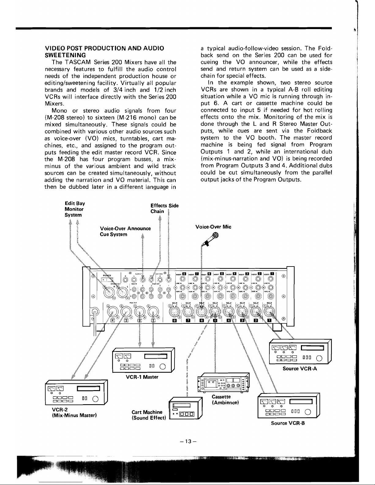
VIDEO POST PRODUCTION AND AUDIO
SWEETENING
The TASCAM Series 200 Mixers have al1 the
necessary features to
fulfill the audio contro1
needs of the independent production house or
editinglsweetening facility. Virtually
al1
popular
brands and models of 314 inch and
112 inch
VCRs
will interface directly with the Series 200
Mixers.
Mono or stereo audio signals from four
(M-208 stereo) to sixteen (M-216
mono) can be
mixed simultaneously. These signals could be
combined with various other audio sources such
as
voice-over (VO) mics, turntables, cart ma-
chines, etc., and assigned to the program out-
puts feeding the edit master record VCR. Since
the M-208 has four program busses, a mixminus of the various ambient and wild track
sources
can be created simultaneously, without
adding the narration and
V0 material. This can
then be dubbed later in a different language in
a
typical audio-follow-video session. The Fold-
back send on the Series 200 can be used for
cueing the
V0 announcer, while the effects
send and return system
can be used
as
a
side-
chain for special effects.
In the example shown, two stereo source
VCRs are shown in
a
typical A-B roll editing
situation while
a
V0 mic
is
running through in-
put 6. A cart or cassette machine could be
connected to input
5
if needed for hot rolling
effects onto the mix. Monitoring of the mix
is
done through the L and R Stereo Master Out-
puts, while cues are sent via the Foldback
system to the
V0 booth. The master record
machine
is
being fed signal from Program
Outputs
1
and 2, while an international dub
(mix-minus-narration and
VO)
is
being recorded
from Program Outputs 3 and 4. Additional dubs
could be cut simultaneously from the
parallel
output jacks of the Program Outputs.
Edit Bay
Effects Side
Monitor
Voice-Over Mic
Source VCR-A
VCR-2
(Mix-Minus Master)
(Sound Effect)
Source VCR-B
 Loading...