

Page 1

TASCAM
TEAC Professional Division
102MK1I
Master Cassette Deck
9101399200
TASCAM 102MKn
I
I
I
■ I
c
A
CAUTION
RISK OF ELECTRIC SHOCK
DO MOT OPEN
A
I
^ I
MANUAL
CAUTION: TO REDUCE THE RISK OF ELECTRIC SHOCK, DO NOT REMOVE COVER
A
The lightning flash with arrowhead symbol, within an equilateral triangle, is intended to alert the user
to the presence of uninsulated “dangerous voltage” within the product’s enclosure that may be of
sufficient magnitude to constitute a risk of electric shock to persons.
(OR BACK). NO USER-SERVICEABLE PARTS INSIDE. REFER SERVICING TO
QUALIFIED SERVICE PERSONNEL.
3
The exclamation point within an equilateral triangle is intended to alert the user to the presence of
A
This appliance has a serial number located
on the rear panel. Please record the model
number and serial number and retain them for
your records.
Model number
Serial number
______________________
______________________
important operating and maintenance (servicing) instructions in the literature accompanying the
appliance.
WARNING: TO PREVENT FIRE OR SHOCK
HAZARD, DO NOT EXPOSE THIS
APPLIANCE TO RAIN OR MOISTURE.
Page 2
Important Safety Instructions
CAUTION:
• Read all of these Instructions.
• Save these Instructions for later use.
• Follow all Warnings and Instructions marked on the audio
equipment.
1) Read instructions — All the safety and operating instructions
should be read before the product is operated.
2) Retain instructions — The safety and operating instructions
should be retained for future reference.
3) Heed Warnings — All warnings on the product and in the
operating instructions should be adhered to.
4) Follow instructions — All operating and use instructions shoud
be followed.
5) Cleaning — Unplug this product from the wall outlet before
cleaning. Do not use liquid cleaners or aerosol cleaners. Use a damp
cloth for cleaning.
6) Attachments — Do not use attachments not recommended by the
product manufacturer as they may cause hazards.
7) Water and Moisture — Do not use this product near water - for
example, near a bath tub, wash bowl, kitchen sink, or laundry tub; in a
wet basement; or near a swimming pool; and the like.
8) Accessories .— Do not place this product on an unstable cart,
stand, tripod, bracket, or table. The product may fall, causing serious
injury to a child or adult, and serious damage to the product. Use only
with a cart, stand, tripod, bracket, or table recommended by the
manufacturer, or sold with the product. Any mounting of the product
should follow the manufacturer’s instructions, and should use a
mounting accessory recommended by the manufacturer.
9) A product and cart combination should be moved with care. Quick
stops, excessive force, and uneven surfaces may cause the product and
cart combination to overturn.
10) Ventilation — Slots and openings in the cabinet are provided for
ventilation and to ensure reliable operation of the product and to protect
it from overheating, and these openings must not be blocked or
covered. The openings should never be blocked by placing the product
on a bed, sofa, rug, or other similar surface. This product should not be
placed in a built-in installation such as a bookcase or rack unless proper
ventilation is provided or the manufacturer’s instructions have been
adhered to.
11) Power Sources — This product should be operated only from
the type of power source indicated on the marking label. If you are not
sure of the type of power supply to your home, consult your product
dealer or local power company. For products intended to operate from
battery power, or other sources, refer to the operating instructions.
12) Grounding or Polarization — This procuct may be equipped
with a polarized altemating-current line plug (a plug having one blade
wider than the other). This plug will fit into the power outlet only one
way. This is a safety feature. If you are unable to insert the plug fully
into the outlet, try reversing the plug. If the plug should still fail to fit,
contact your electrician to replace your obsolete outlet. Do not defeat
the safety purpose of the polarized plug.
13) Power-Cord Protection — Power-supply cords shoud be routed
so that they are not likely to be walked on or pinched by items placed
upon or against them, paying particular attention to cords at plugs,
convenience receptacles, and the point where they exit from the product.
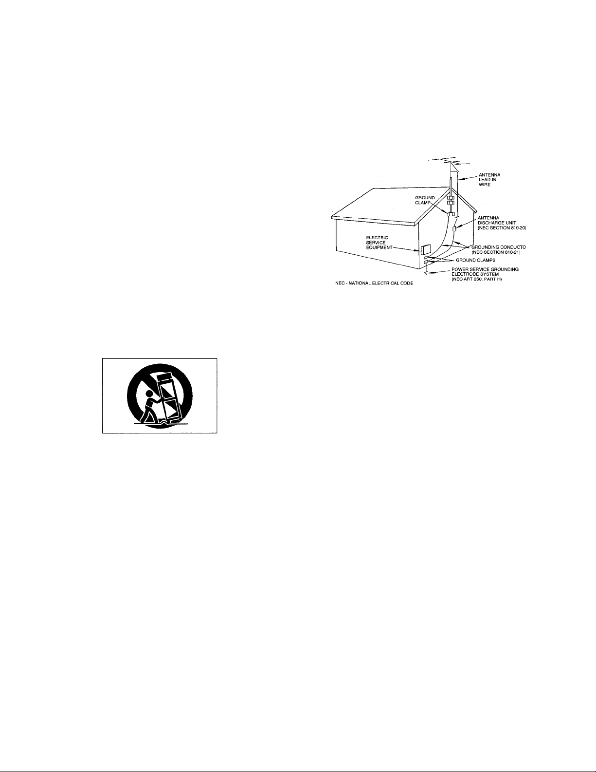
14) Outdoor Antenna Grounding — If an outside antenna or cable
system is connected to the product, be sure the anterma or cable system
is grounded so as to provide some protection against voltage surges and
built-up static charges. Article 810 of the National Electrical Code,
ANSI/NFPA 70, provides information with regard to proper grounding
of the mast and supporting structure, grounding of the lead-in wire to an
antenna discharge unit, size of grounding conductors, location of
antenna-discharge unit, connection to grounding electrodes, and
requirements for the grounding electrode.
"Note to CATV system installer;
This reminder is provided to call the CATV system installer’s attention
to Section 820-40 of the NEC which provides guidelines for proper
grounding and, in particular, specifies that the cable ground shall be
connected to the grounding system of the building, as close to the point
of cable entry as practical.
Example of Antenna Gronnding as per
National Electrical Code, ANSI/NFPA 70
15) Lightning — For added protection for this product during a
lightning storm, or when it is left unattended and unused for long
periods of time, unplug it from the wall outlet and disconnect the
antenna or cable system. This will prevent damage to the product due to
lightning and power-line surges.
16) Power Lines — An outside antenna system should not be located
in the vicinity of overhead power lines or other electric light or power
circuits, or where it can fall into such power lines or circuits. When
installing an outside antenna system, extreme care should be taken to
keep from touching such power lines or circuits as contact with them
might be fatal.
17) Overloading — Do not overload wall outlets, extension cords, or
integral convenience receptacles as this can result in risk of fire or
electric shock.
18) Object and Liquid Entry — Never push objects of any kind into
this product through openings as they may touch dangerous voltage
points or short-out parts that could result in a fire or electric shock.
Never spill liquid of any kind on the product.
19) Servicing — Do not attempt to service this product yourself as
opening or removing covers may expose you to dangerous voltage or
other hazards. Refer all servicing to qualified service personnel.
20) Damage Requiring Service — Unplug this product from the
wall outlet and refer servicing to qualified service personnel under the
following conditions:
a) when the power-supply cord or plug is damaged.
b) if liquid has been spilled, or objects have fallen into the product.
c) if the product has been exposed to rain or water.
d) if the product does not operate normally by following the operating
instructions. Adjust only those controls that are covered by the
operating instructions as an improper adjustment of other controls may
result in damage and will often require extensive work by a qualified
technician to restore the product to its normal operation.
e) if the product has been dropped or damaged in any way.
f ) when the product exhibits a distinct change in performance - this
indicates a need for service.
21) Replacement Parts — When replacement parts are required, be
sure the service technician has used replacement parts specified by the
manufacturer or have the same characteristics as the original part.
Unauthorized substitutions may result in fire, electric shock, or other
hazards.
22) Safety Check — Upon completion of any service or repairs to
this product, ask the service technician to perform safety checks to
determine that the product is in proper operating condition.
23) Wall or Ceiling Mouting — The product shoud be mounted to a
wall or ceiling only as recommended by the manufacturer.
24) Heat — The product should be situated away from heat sources
such as radiators, heat registers, stoves, or other products (including
amplifiers) that produce heat.
•2-
Page 3
REFERENCE ILLUSTRATIONS
Display
IN NORTH AMERICA USE ONLY ON 120 V SUPPLY.
DANS L'AMERIQUE DU NORD: UTILISABLE SUR 120 V
D'ALIMENTATION UNIQUEMENT.
CONNECTIONS (Fig. 1)
• Turn off power for all equipment before
making connections.
• Read instructions of each component
you intend to use with the deck.
OUTPUT terminals
OUTPUT Terminals on the tape deck
should be connected to the TAPE PLAY or
LINE IN jacks on the amplifier/receiver.
LINE IN terminals
LINE IN Terminals on the tape deck
should be connected to the REC OUT jacks
on the amplifier/receiver.
Power cord
Be sure to connect the power cord to an
AC outlet which supplies the correct
voltage, as set bythe voltage selector.
* •
Page 4

Fig.l
Stereo Amplifier
Fig.3
Fig. 5 Connection for CD synchro dubbing
Fig. 4
Capstan
To AC outlet
Page 5

PRECAUTIONS
FEATURES AND CONTROLS
(See page 3.)
IMPORTANT (for U.K. Customers)
Environment
Avoid using the deck in the following
conditions:
• At high temperatures (near a heater,
exposed to direct sunlight, etc.).
• At extremely low temperatures.
• Where there is excessive humidity.
• In a dusty atmosphere.
• Where power line voltage fluctuations
are severe (in which case the use of a
voltage regulator may be advisable).
Cassette Tape (Fig. 2)
Tape Selection:
For the automatic tape select function to
work properly, metal and chrome (cobalt)
tapes must have identification holes.
Tape Handling:
Do not store tapes in the following places:
• On top of heaters, exposed to direct
sunlight or in any other places with high
temperatures.
• Near speakers, on TV sets or amplifiers
or where they would be exposed to
strong magnetic fields.
• Where humidity is high and in dirty,
dusty places.
• Avoid dropping or subjecting cassettes
to excessive shocks.
• As C-120 tapes are physically weak and
could become entangled in the
transport mechanism, do not use them.
Voltage Conversion
(General export models only) (Fig. 3)
Be sure to remove the power cord from
the AC outlet before repositioning the
voltage converter switch.
1. Locate the voltage selector on the rear
panel.
2. Using a flat-bladed screwdriver, set to
the appropriate 230 V or 120 V position
according to your area.
THE APPLIANCE CONFORMS WITH
EEC DIRECTIVE 87/308/EEC REGARD
ING INTERFERENCE SUPPRESSION.
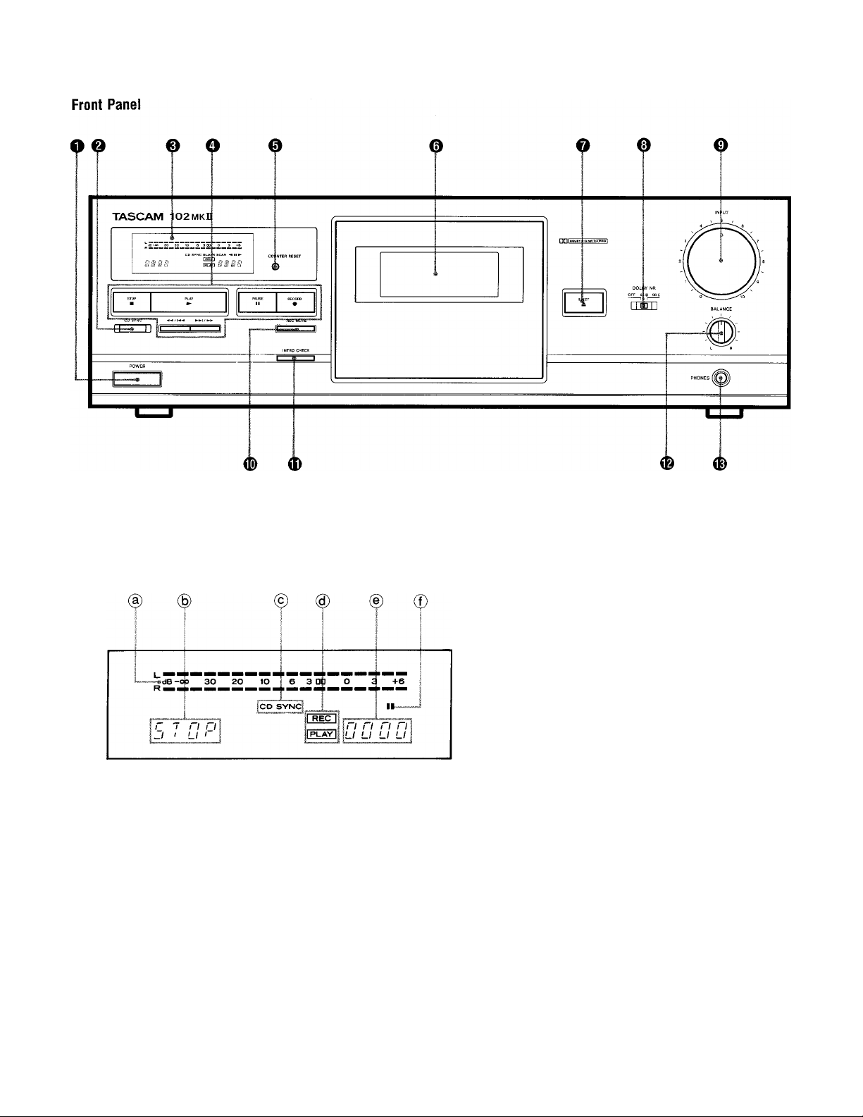
FRONT PANEL
O POWER Switch
Note: If you switch the power off, be sure
to wait for more than 3 seconds before
switching it on again.
@ CD SYNC Button
0 Display Window
(a) Peak Level Meter
® Transport Mode Indicators
© CD SYNC Indicator
(§) REC/PLAY Mode Indicators
© Multi Counter
© Pause Indicator
O Tape Operation Buttons
STOP Button
► : Play Button
PAUSE Button
RECORD Button
I / : Rewind/CPS Button
• / : Fast Forward/CPS Button
0 COUNTER RESET Button
Pressing the COUNTER RESET Button
resets the multi-counter to "0000".
0 Cassette Holder
O EJECT Button
0 DOLBY NR Select Switch
OFF: Set to this position when you do
not want to use any noise
reduction system.
□□ B: Set to this position when making
a recording using the Dolby B
noise reduction system, or
playing back tapes recorded
with Dolby B NR.
□□ C: Set to this position when making
a recording using the Dolby C
noise reduction system, or
playing back tapes recorded
with Dolby C NR.
DO NOT cut off the mains plug from
this equipment. If the plug fitted is not
suitable for the power points in your
home or the cable is too short to reach
a power point, then obtain an
appropriate safety approved extension
lead or consult your dealer.
If nonetheless the mains oluo is cut
off, remove the fuse and dispose of the
plug immediately, to avoid a possible
shock hazard by inadvertent
connection to the mains supply.
If this product is not provided with a
mains plug, or one-has to be fitted, then
follow the instructions given below:
IMPORTANT. DO NOT make any
connection to the larger terminal which
is marked with the letter E or by the
safety earth symbol Ф or coloured
GREEN or GREEN-and-YELLOW.
The wires in the mains lead on this
product are coloured in accordance
with the following code:
BLUE: NEUTRAL
BROWN: LIVE
As these colours may not correspond
with the coloured markings identifying
the terminals in your plug proceed as
follows:
The wire which is coloured BLUE must
be connected to the terminal which is
marked with the letter N or coloured
BLACK.
The wire which is coloured BROWN
must be connected to the terminal
which is marked with the letter L or
coloured RED.
When replacing the fuse only a
correctly rated aonroved tvoe should
be used and be sure to re-fit the fuse
cover.
Dolby noise reduction and HX Pro
headroom extension manufactured
under license from Dolby Laboratories
Licensing Corporation. HX Pro
originated by Bang
"DOLBY”, the double-D symbol □□ and
"HX PRO” are trademarks of Dolby
Laboratories Licensing Corporation.
& Olufsen.
0 INPUT Control
0 REC (Record) MUTE Button
® INTRO CHECK Button
® BALANCE Control
0 PHONES Jack
Plug stereo headphones into this jack for
private listening or monitoring.
-5-
IF IN DOUBT — CONSULT A
COMPETENT ELECTRICIAN.
Page 6

OPERATIONS
Loading a Cassette Tape
1. Use your finger or a pencil to turn
the cassette's hub and take up any
slack tape.
Note: Avoid touching the tape.
Fingerprints attract dust and dirt.
2. Press the eject button (±)* to open
the cassette compartment door.
3.
Load the cassette tape with its
open edge facing down.
4.
Gently close the compartment
door.
INTRO CHECK Function
This function makes searching for a
specific tune much easier by detecting
the beginning of each tune in sequence.
1. Press the INTRO CHECK button.
2. The deck will fast-wind to the
beginning of a tune, play the first 15
seconds (approx.), then fast-wind to
the beginning of the next tune, from
which point the cycle starts again.
3. To release the intro check function,
press the STOP button.
• When the >■ (Play) button is pressed
during the intro check mode, normal
playback resumes.
• Notes:
• he cassette holder cannot
opened during recording
playback.
• If the power has been switched off
during play or recording, ejecting the
cassette may be impossible. In
such a case, switch the power on
and press the eject button again.
Playback
1. Press the POWER switch to ON.
2. Load a pre-recorded cassette.
3. Set the DOLBY NR switch as required.
4. Press the ►button to start playback.
5. Adjust the volume with the amplifier's
volume control.
• To stop playback, press the STOP
button.
Transport Mode Indicators
Deck Operation Indicators
Stop
Playback/Record
Pause
Fast-Forward
Rewind
r 7 n n
-II LI 1
ri 1 n 1 1
1 L 1 1 -1
ri n 1 1 r
1 1 1 LI -1
r r
1 1
n r 1 1
Is l_ /A/
be
CPS (Computomatic Program
Search) Function
When the ►H button is pressed, the
next tune is counted as "1" and when
the button is pressed, the current
tune is counted as “1".
2.
CPS allows the selection and playback of
any tune up to 20 tunes ahead or before
the one being played. This function
operates by detecting blank spaces of at
least 4 seconds between tunes. These
The tape is fast-wound to detect
blanks between tunes until the
required tune is reached. Then
playback starts from the beginning of
the designated tune.
blanks can be created using the REC
MUTE Function.
1. During playback, press the or
►►I button repeatedly until the
or
number of tunes to be skipped appears
in the counter display. Use the
button for searching a tune following
the current tune and button for a
tune before the current tune. Refer to
the chart "How to Select any Required
Tune Using CPS".
• If, by using the the required CPS
number setting is exceeded, use the
button to count down the CPS
number until the required CPS number
is displayed.
Notes on CPS
CPS operates by detecting and counting
blanks of about 4 seconds, the standard
interval between tunes. Therefore, with
the following types of tapes, search
functions may not work correctly.
• When the intervals between tunes
cannot be detected.
- Intervals of less than 4 seconds.
- High levels of noise in intervals.
- Long low level sections (in classical
music, etc.)
This problem can be corrected using the
REC MUTE function.
How to Select any Required Tune Using CPS
Ex: See (1). To select the 3rd tune past the current tape position, seiect "CP03”.
(1} Current tape position
(CP^ /T?i77/
\ ! (3) ®
In example (1). If T is less than
4 seconds, it will not be counted
as a blank. Designate "CP02”
instead of "CP03" to select the
3rd tune in this case.
(3)
1 1 ?.
S3
------------------
Following I Before
I
Current tape position
Foilowing j Before
(mei
(2)
(4)
3-
Direction of
’ tape travel
—►
. Direction of
tape travei
■6-
Page 7

Recording
Recording from a stereo system:
1. Press the POWER switch to ON.
2. Load a recordable cassette.
3. Set the DOLBY NR switch as desired.
4. Press the RECORD button. The REC
and II indicators will light to show
that the deck is in the record-pause
mode. This enables you to adjust the
recording level without actually
recording on the tape.
5. Adjust the recording level with the
INPUT control so that the loudest
sound to be recorded just makes the
meters briefly reach around the ”0 dB"
point (for Normal or Chrome tapes) or
the “+3 dB" point (for Metal tapes).
6. To adjust the balance of the left and
right channel input signals, use the
BALANCE control.
7. Press the ► or PAUSE button to start
recording.
Notes:
• To stop recording, press the STOP
button.
• To momentarily stop recording, press
the PAUSE button. To resume
recording, press the ► or PAUSE
button.
CAUTION:
Recording pre-recorded tapes, records,
or other published or broadcast
material may infringe copyright laws.
Check these laws before recording.
3. For a blank of more than 4 seconds
During recording, hold the REC MUTE
button depressed for longer than 4
seconds. A blank space will be left as
long as the button is pressed. Release
the button to enter the record-pause
mode. To restart recording, press the
PAUSE button.
4. For a blank of less than 4 seconds
After pressing the REC MUTE button
during recording, press the PAUSE
button before 4 seconds has elapsed.
The deck will stop and enter the record-
pause mode at the point at which the
PAUSE button is pressed. To restart
recording, press the PAUSE button
again.
Note:
• During record muting operation (while
the RECORD indicator is blinking),
pressing the REC MUTE button again
will release the record muting
operation and recording will restart
without stopping the tape.
CD Synchro Dubbing (Fig. 5)
By connecting the deck to a TEAC CD
synchro compatible CD player which has a
CD/DECK SYNC terminal on its rear panel,
dubbing (recording) synchronized with the
CD player is possible.
Preparation
1. Connect the deck's CD/DECK SYNC
terminal to the CD player's CD/DECK
SYNC terminal using an optional cable.
2. Perform programming of the "time
edit", etc. functions of the CD player
beforehand (refer to the instructions
of the CD player).
3. Set the source to CD using the
amplifier's source select buttons.
4. Set the recording level.
5. Set the deck and the CD player to the
stop mode.
6. Press the CD SYNC button of the deck.
The CD player will start automatically
approx. 1 sec after the deck starts
recording and dubbing will be
performed. (The CD SYNC indicator
lights.)
To stop temporarily during dubbing:
To temporarily stop CD synchro dubbing
(A) Press the STOP button of the deck.
The CD player will return to the
beginning of the current tune and
pause there. To restart, press the
deck's CD SYNC button.
(B) Press the stop button of the CD
player. The deck enters the rec/pause
mode. To restart, press the CD
player's play button.
* When the CD player has entered the
pause mode, it stands by after returning
to the beginning of the tune that has
just been played.
Erasing
Anything previously recorded on the tape
will automatically be erased when you
make a new recording on it. It can also be
erased by “recording" on it with the INPUT
control set to "0".
Record Muting Operation
1. Automatic spacing operation for 4-
second blanks (during recording)
Press the REC MUTE button during
recording. The tape movement
continues and a blank space of about 4
seconds is recorded (the RECORD
indicator blinks). The deck then enters
the record-pause mode automatically
(both the REC and II indicators light).
To restart recording, press the PAUSE
button (the II indicator goes off).
2. Automatic spacing operation for 4-
second blanks (during record-pause)
In the record-pause mode, pressing the
REC MUTE button will initiate the
above record-muting operation
automatically. The deck then returns to
the record-pause mode.
CD synchro dubbing operation
The shaded portions (!!□) in the following indicate the CD synchro dubbing mode.
Start of CD synchro dubbing
Deck's CD SYNC button ON-
Deck operation
CD player operation
Stop
Stop
Recording
Playback
(A: Operation at the deck)
CD SYNC button ON-
Stop Recording
Return to the beginning of
the tune, then pause.
Playback ^
Deck operation
CD player operation
STOP button ON—
Recording
Playback
(B: Operation at the CD player)
Deck operation
CD player
Recording Rec/pause
Playback Stop
STOP button ON-
Recording
Playback
PLAYt utton ON
-7-
Page 8

* When recording is done up to the end of
the tape, the CD player stands by after
returning to the beginning of the tune
that has just been played.
Note
If the CD player is connected to the stereo
amplifier using an optical cable, synchro
dubbing is not possible. If synchro dubbing
is required, you must connect the deck's
analog output using pin plug cords.
MAINTENANCE (Fig. 4)
The heads and tape path should be
cleaned and demagnetized periodically.
Cleaning Tape Path
• Apply head cleaning fluid* * to a cotton
bud or soft cloth, and lightly rub the
heads, capstan and all metal parts in
the tape path.
• Also clean the pinch roller using rubber
cleaning fluid*.
• Both are available in TEAC Tape
Recorder Cleaning Kits HC-2 and RC-2 in
the U.S.A. or TZ-261 in other areas.
Demagnetizing Heads
Be sure that the power is off, then
demagnetize the heads using a TEAC E-3
demagnetizer. For details of its use, read
its instructions.
TROUBLESHOOTING
Basic troubleshooting of a cassette tape
deck is similar to troubleshooting any
other electrical or electronic equipment.
Always check the most obvious possible
causes first. To give you a few ideas of
what to look for, check the following:
• No power: Is the power cord
connected?
• No audio output: Have all connections
been made cffrrectly?
• Low sound quality: Are the heads dirty
or magnetized? Are you using good
quality tape? Has the correct NR
System been selected?
• Impossible to enter the record mode:
Are the record protection tabs of the
cassette in place?
DOLBY HX PRO
Dolby HX Pro is an "active bias” technique
that can improve the quality of audio tape
recordings. High-level high frequencies can
be recorded more accurately, without
sacrificing signal-to-noise ratio, while such
side effects of tape saturation as distortion
are reduced.
What Is Bias?
Bias is a very high-frequency signal generat
ed within a tape deck and recorded on the
tape simultaneously with the program
material. This inaudible signal allows a low
noise, low distortion recording and flat
frequency response. Different magnetic tape
formulations require different amounts
of bias for optimum performance. If the
bias level is too high, high-frequency
Maximum Output Level (MOL) decreases.
The Problem of Self-Bias
Unfortunately, bias level is often influenced
by the signal being recorded. The high fre
quencies contained in some music act as
bias. This unpredictable source of bias is
added to the existing bias, resulting in a loss
of high-frequency response. As the high-
frequency content of the signal increases,
the ability of the recorder to record high
frequencies (MOL) decreases. This pheno
menon is called self-biasing.
How Dolby HX Pro Solution
The Dolby HX Pro monitors the high-
frequency content of the program material
and adjusts the recorder bias oscillator to
maintain a constant total bias level. The
result is improved high-frequency response
and lower distortion. Depending on the type
of tape, the improvement in headroom can
be 6 dB or more.
The Benefits
With Dolby HX Pro, it is easier to make
more accurate recordings of the kind of
music which contains high-level high fre
quencies. The improvement is similar to
that of high-performance tape over conven
tional tape, so regardless of the type of
tape used, the results will sound better.
Most important of all, Dolby HX Pro
requires no decoding process. Once the
tape is recorded with it, the improvements
will be realized when playing the tape back
on any machine.
20Hz 50 100 200 500 1 k 2
Example of improved frequency response
using Dolby HX Pro
INSTALLING THE UNIT INTO A RACK
This unit is provided with a metal fixture for
rack mounting. Use it when installing the
unit into a 19-inch rack.
Howto install
(1) Remove four screws fixing the panel to
the unit. (Do not open the panel.)
* Although the removed screws are not
used to install the metal fixture for rack
mounting, retain them for future use.
(2) Place a metal fixture on the side of the
unit (panel), then secure it using the
provided four screws (M3 x 10).
(3) In a similar way, install a metal fixture to
the other side of the unit.
* See that the metal fixtures are flush
with the top of the panel.
-8-
Page 9

SPECIFICATIONS
Track System:4-track, 2-channel stereo
Heads:
2; 1 Erase and 1 Record/Playback
Type of Tape: Cassette tape C-60 and C-90
(Philips type)
Tape Speeds: 4.76 cm/sec (1-7/8 Ips)
Motor: 1 DC Servo motor
Wow and Flutter (WRMS): 0.06%
Frequency Response (Overall, -20 dB):
25 - 19,000 Hz, Metal tape
25- 18,000 Hz, Cr02tape
25 - 17,000 Hz, Normal tape
Signal-to-Noise Ratio (Overall):
59 dB (NR off, 3% THD Level,
Weighted)
69 dB (Dolby B NR on, over 5 kHz)
79 dB (Dolby C NR on, over 1 kHz)
Fast Winding Time: Approximately 110
seconds for C-60
Inputs: Line: 97 mV, 50k ohms
Outputs: Line: 0.52 V for load impedance of
50k ohms or more
Headphones: 1 mW/8 ohms
Power Requirements:
120/230 VAC, 50-60 Hz
(U.S.A./Canada/General Export
Model)
230 V AC, 50 Hz (Europe Model)
240 V AC, 50 Hz (UK/Australia
Model)
Power Consumption: 10 W
Dimensions (W x H x D):
435 X 144 X 286 mm
(17-1/8” X 5-11/16” X 11-1/4")
Weight (net): 4 kg (8-13/16 lbs.)
Standard Accessories: Input-output
connection cords
•
• Specifications were determined using
metal tape except as noted.
• Improvements may result in
specification or feature changing
without notice.
483mm (19")
19.5mm (3/4") 262mm (10-5/16")
1
5.5mm (1/4")
-9-
Page 10

TASCAM
TEAC Professional Division
102MKII
— For CANADA---------------------------------------------
THIS DIGITAL APPARATUS DOES NOT EXCEED
THE CLASS B LIMITS FOR RADIO NOISE
EMISSIONS FROM DIGITAL APPARATUS AS SET
OUT IN THE RADIO INTERFERENCE REGULA
TIONS OF THE CANADIAN DEPARTMENT OF
COMMUNICATIONS.
For CANADA-------------------------------------------
AC POWER CORD CONNECTION
CAUTION :
TO PREVENT ELECTRIC SHOCK MATCH WIDE
BLADE OF PLUG TO WIDE SLOT, FULLY INSERT.
TEAC CORPORATION
TEAC AMERICA, INC.
TEAC CANADA LTD.
TEAC UK LIMITED
TEAC DEUTSCHLAND GmbH
TEAC FRANCE S.A.
TEAC NEDERLAND BV
TEAC AUSTRALIA PTY., LTD.
A.C.N. 005 408 462
TEAC ITALIANA S.p.A.
3-7-3, Nakacho, Musashino-shi, Tokyo 180, Japan Phone: (0422) 52-5081
7733 Telegraph Road, Montebello, California 90640 Phone: (213) 726-0303
340 Brunei Road, Mississauga, Ontario L4Z 2C2, Canada Phone: 905-890-8008
5 Marlin House, Marlins Meadow, The Croxley Centre, Watford, Herts. WD1 8YA, U.K. Phone: 0923-819631
Bahnstrasse 12, 65205 Wiesbaden-Erbenheim, Germany Phone: 0611-71580
17, Rue Alexis-de-Tocqueville, CE 005 92182 Antony Cedex, France Phone: (1) 42.37.01.02
Perkinsbaan 11,3439 ND Nieuwegein, Nederland Phone: 03-402-30229
106 Bay Street, Port Melbourne, Victoria 3207, Australia Phone: (03) 646-1733
Via C. Cantu 5, 20092 Cinisello Balsamo, Milano, Italy Phone: 02-66010500
LE PRÉSENT APPAREIL NUMÉRIQUE N'ÉMET PAS
DE BRUITS RADIOÉLECTRIQUES DÉPASSANT LES
LIMITES APPLICABLES AUX APPAREILS NUMÉRI
QUES DE CLASSE B PRÉSCRITES DANS LE
RÉGLEMENT SUR LE BROUILLAGE RADIO
ÉLECTRIQUE ÉDICTÉ PAR LE MINISTÈRE DES
COMMUNICATIONS DU CANADA.
CORDE DE CONNEXION CA ATTENTION :
POUR ÉVITER LES CHOCS ÉLECTRIQUES,
INTRODUIRE LA LAME LA PLUS LARGE DE LA
FICHE DANS LA BORNE CORRESPONDANTE DE
LA PRISE ET POUSSER JUSQU' AU FOND.
PRINTED IN TAIWAN 1294-M-1008A
 Loading...