

Page 1
Page 2
Page 3

English ........................................................................................................................ 2
Dansk ....................................................................................................................... 25
Deutsch ..................................................................................................................... 48
V 1.23
Page 4

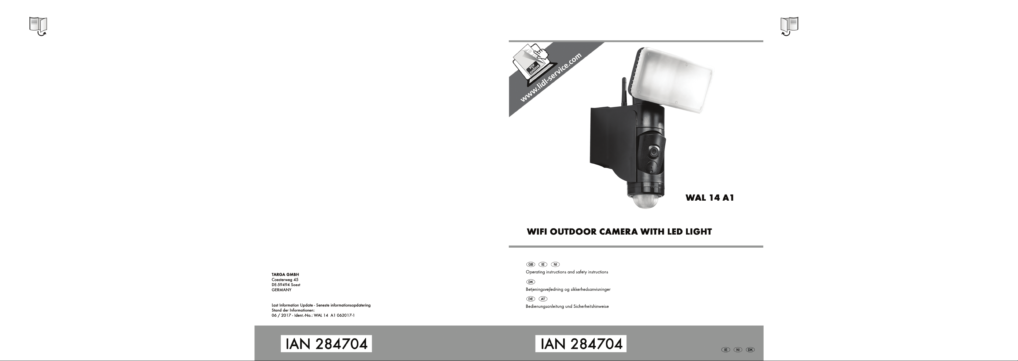
WAL 14 A1
Contents
1. Intended use ........................................................................................................... 3
2. Trademark information .......................................................................................... 3
3. Package contents ................................................................................................... 4
4. Technical specifications ........................................................................................... 5
5. Safety instructions .................................................................................................. 6
5.1. Infringing third-party rights / Rights to own images .............................................................................. 7
6. Copyright ............................................................................................................... 8
7. Before you start ...................................................................................................... 9
7.1. The right place for mounting ................................................................................................................... 9
7.2. Tools required .......................................................................................................................................... 9
7.3. Before mounting ...................................................................................................................................... 9
7.4. Mounting ............................................................................................................................................... 10
7.5. Setting up the LED emitter, camera and movement sensor ................................................................ 13
8. Getting started ..................................................................................................... 15
8.1. Inserting / removing the memory card ............................................................................................... 15
8.2. Downloading and installing the control app ...................................................................................... 16
8.2.1. Operating instructions for the control app ................................................................................. 16
8.3. Access data (camera name / password) ........................................................................................... 19
8.3.1. Camera name .............................................................................................................................. 19
8.3.2. Username ..................................................................................................................................... 19
8.3.3. Password ...................................................................................................................................... 19
8.3.4. Applying the app settings ............................................................................................................ 19
8.4. Restoring factory settings ..................................................................................................................... 20
8.5. LED displays .......................................................................................................................................... 20
9. Maintenance/cleaning .......................................................................................... 21
10. Troubleshooting ................................................................................................. 21
11. Environmental regulations and disposal inform ation .......................................... 22
12. EU Declaration of Conformity Notice ................................................................... 22
13. Warranty and servicing advice ........................................................................... 23
2 - English
Page 5

WAL 14 A1
Congratulations!
By purchasing the WAL 14 A1 WiFi outdoor camera, you have opted for a quality product.
Before first using it, familiarise yourself with the way the outdoor camera works and read these operating
instructions through carefully. Be careful to follow the safety instructions and only use the outdoor camera
as described in the operating instructions and for the applications given.
Keep these operating instructions near the product for later reference. If you pass the outdoor camera on
to someone else, make sure to give them all the relevant documents with it.
1. Intended use
The WiFi outdoor camera WAL 14 A1 is an information electronics device which is designed for
automatic surveillance of indoor and outdoor areas. In poor visibility, the LED light can also be switched
on to illuminate the area under surveillance. The outdoor camera is only suitable for permanent mounting
(wall mounting). The power supply must be via the building's electrical circuit. It is not designed for
commercial use. This device fulfils all standards and directives listed in the Declaration of Conformity. Any
modifications to the outdoor camera other than changes agreed with the manufacturer may result in these
standards no longer being met.
2. Trademark information
Apple®, iPhone® and iPad® are registered trademarks, App Store is a service mark of Apple Inc.,
registered in the USA and other countries.
®
Google
Other names and products may be the trademarks or registered trademarks of their respective owners.
and Android® are registered trademarks of Google Inc.
English - 3
Page 6
WAL 14 A1
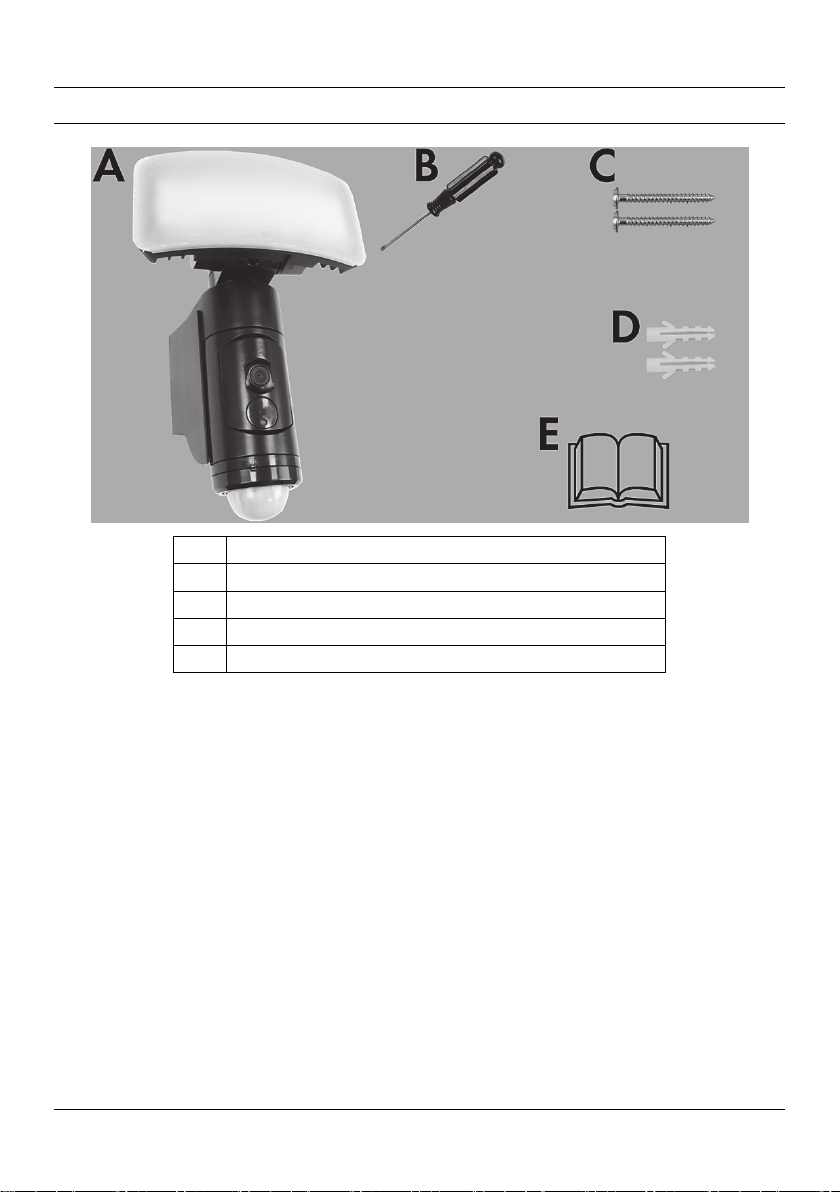
3. Package contents
A WiFi outdoor camera WAL 14 A1
B Special screwdriver
C 2x screws, 4 x 40mm
D 2x dowels, 6 x 27mm
E Operating instructions (lineart illustration)
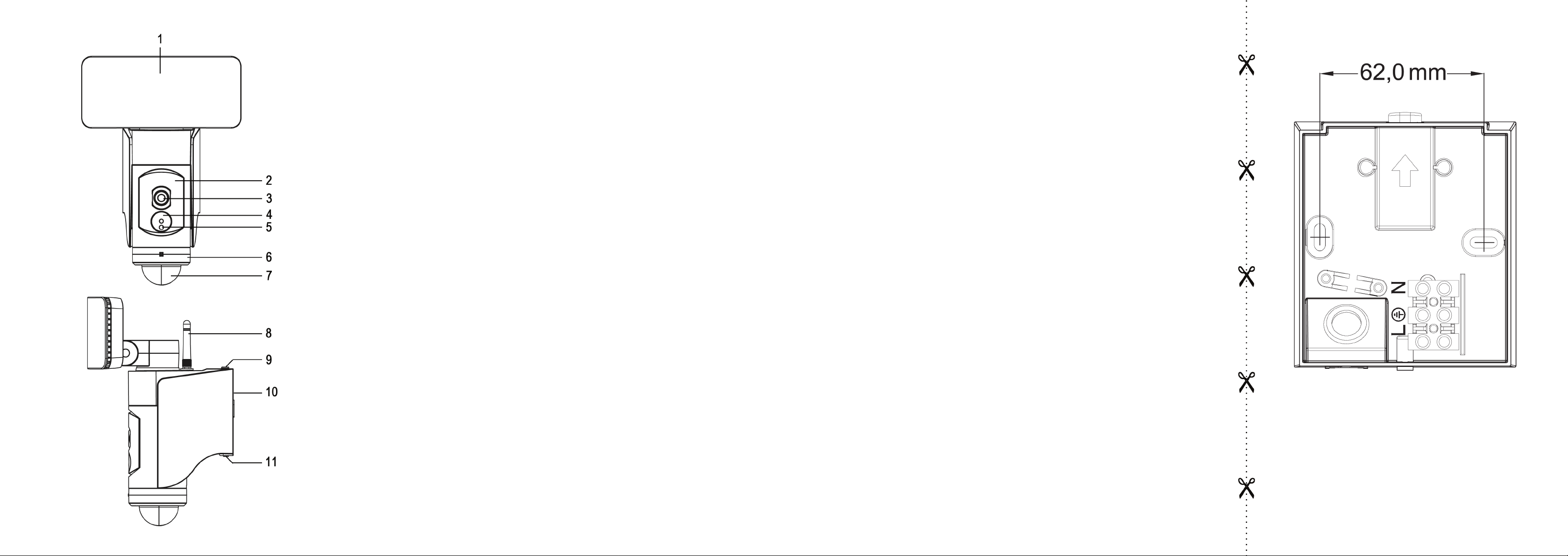
These operating instructions have a fold-out cover. On the inside of the cover, the outdoor camera is
shown with figures indicated. The meanings of the numbers are as follows:
1 LED emitter
2 Camera holder
3 Camera
4 RESET button cover
5 Power LED (displays various operating statuses)
6 Adjuster ring (for horizontal alignment of the camera and movement sensor)
7 Movement sensor
8 WiFi antenna
9 Catch (for mounting plate)
10 Mounting plate
11 Screw (to secure the camera)
4 - English
Page 7
WAL 14 A1
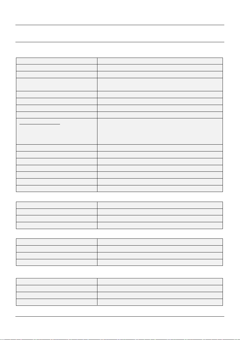
4. Technical specifications
The rating plate for the outdoor camera can be found on the mounting plate (10).
LED emitter
Model name: WAL 14 A1
Operating voltage: 220 – 240 V~, 50 Hz
Total power consumption: approx. 20 Watt
Power consumption of light without
auxiliaries:
Lights: 28 LEDs at 0.5 W each
Luminous flux: approx. 1250 lumen
Colour temperature: Approx. 5,000K
Energy efficiency class of LED emitter: A+
Adjustable light time:
For movement sensor:
Manual setting:
Max. area projected: Approx. 50 m² if mounted at height of approx. 2.50 m
Operating position: Vertical – LED-emitter on top, movement sensor underneath
Ambient temperature: -33°C - + 40°C
Safety class: I (with ground wire connection)
Degree of protection: IP54
Dimensions (W x D x H): approx. 179 x 165 x 256 mm
Weight: approx. 920 g
Camera:
Resolution: 1280*720 pixels
Frame rate: 1-20 images per second (adjustable)
Viewing angle: Approx. 94° horizontal, approx. 48° vertical
Micro SD card (not included): Class 10, max. 128 GB
Movement sensor:
Sensor detection angle: Max. 180°
Sensor range: Max. 10 m
Light sensitivity: Adjustable using the app
Swivel range (mechanical): Approx. 120° horizontal
WiFi / Control app L-Guard HD
WiFi standard: 802.11 b / g / n
WiFi frequency band: 2.4GHz
Wi-Fi transmission power: approx. 8.7 mW
App compatibility: iOS 8.0 (and higher) / Android 4.4 (and higher)
The technical data and design may be changed without prior notice.
approx. 18 Watt
Approx. 10 sec. (+/- 5 sec.) to approx. 20 min. (+/- 5 min.)
3 hours, 6 hours or continuous when dark (adjustable using
twilight sensor)
English - 5
Page 8

WAL 14 A1
5. Safety instructions
Before you use this device for the first time, please read the following notes in this manual and heed all
warnings, even if you are familiar with handling electronic devices. Keep these operating instructions in a
safe place for future reference. If you sell the device or pass it on, it is essential that you also hand over
these operating instructions as they are part of the product.
DANGER! This symbol and the word "Danger" denote a potentially dangerous
situation. Ignoring it can lead to severe injury or even death.
WARNING! This symbol and the word “WARNING” denote important
information required for the safe operation of the product and for the safety of its
users.
DANGER! This symbol denotes danger for human health and risk of death and/or
risk of damage to property due to electric shock.
This symbol denotes further information on the topic.
The outdoor camera has a ground conductor connection. The ground conductor
(green/yellow) must be connected to the terminal shown.
Significance of IP54 protection:
The WiFi outdoor camera is protected against dust at damaging levels and against water
splashes from all sides.
DANGER! Electrical devices are not suitable for children. Never allow children to use electrical
devices unsupervised. Children may not understand that they can be dangerous. Keep the
packaging materials out of the reach of children. Risk of suffocation!
DANGER! The outdoor camera must be connected to the 230 V mains power by a qualified
electrician.
The outdoor camera complies with Safety Class I, which means the ground conductor must
always be connected to the camera.
DANGER! If you notice smoke or strange noises or smells, disconnect the device from the mains
power immediately by switching the relevant circuit breaker to the “0” position. If this occurs, the
device should no longer be used and should be inspected by authorised service personnel.
Never inhale smoke from a possible device fire. If you do inadvertently inhale smoke, seek
medical attention. Smoke inhalation can be damaging to your health.
6 - English
Page 9
WAL 14 A1
DANGER! The housing of the outdoor camera must not be damaged. If the housing is
damaged, there is a risk of electric shock.
DANGER! Do not use the outdoor camera in environments with a high risk of explosion from
flammable gases, vapours or dust. There is risk of explosion.
DANGER! Never open the housing of the outdoor camera apart from to change the memory
card. The mains power must be switched off for all work on the outdoor camera, even replacing
the memory card! If the housing is opened, there is a risk of electric shock.
DANGER! Risk of injury! Never use optical instruments such as a magnifying glass to look
directly into the light beam. This could damage your eyes. If you suspect you have damaged
your eyes, seek medical attention immediately.
DANGER! Risk of fire! Never cover the outdoor camera, as this could cause it to overheat.
DANGER! All repairs must be carried out by a specialist.
WARNING! Do not hang anything from the outdoor camera. The housing is not designed to
support weights. This could damage the outdoor camera.
WARNING! Do not insert foreign bodies into the outdoor camera. This could damage the
outdoor camera.
5.1. Infringing third-party rights / Rights to own images
Rights to own images or pictures are a subset of the general law on personality. They stipulate that all
people have the fundamental right to determine whether and in what context images of them are
published.
Private surveillance cameras (e.g. IP cameras) may not be used to monitor public areas or private areas
belonging to others. This also applies to areas used on a communal basis (e.g. owner or tenant
collective). This means, for example, entrance areas or paths used by multiple people.
What can I monitor with my IP camera?
Video surveillance using an IP camera is permitted for monitoring your own properties.
One restriction: All persons who are or could be affected by the video surveillance must be informed that
surveillance is taking place. In order to comply with this obligation, it is sufficient to affix signs or stickers in
the area monitored. However, these notices must be visible prior to entering the monitored area. If, for
example, you are monitoring your own property with an IP camera, there should be a notice at all
entrances to the property.
When setting up an IP camera, please note the following:
Copyright:
Essentially, everyone has the right to their own image. According to the laws on copyright, images can
only be published without the consent of the people of them if they are incidental next to a landmark or
English - 7
Page 10

WAL 14 A1
similar location. The answer to the question as to whether a person is incidental depends on the
circumstances of the individual case. In order to be safe from a legal perspective, warning signs should be
placed in all areas where recordings with identifiable persons are possible.
Protecting privacy
The images shown must not infringe the privacy of others. Never point your camera at the garden or front
door of your neighbour’s home, even if these places are visible from your own home or from public
places. This does not entitle you to publish these views. In case of doubt, you will need to restrict the
viewing area of the IP camera with a screen.
Personal determinability
Personal determinability is where it can be determined that a specific person was in a specific place at a
specific time. Identification can also be based on a personal identifier such as a vehicle number plate.
Personal determinability must be avoided at all times.
The legal regulations may be different in different countries. Please note the laws in the country of use.
6. Copyright
All the contents of this user manual are protected by copyright and provided to the reader for information
only. Copying data and information without the prior explicit written consent of the author is strictly
forbidden. This also applies to any commercial use of the contents and information. All texts and diagrams
are up-to-date as of the date of printing. Subject to change without notice.
8 - English
Page 11

WAL 14 A1
7. Before you start
Remove the outdoor camera and mounting fittings from the packaging.
Check the outdoor camera for damage. If the outdoor camera is damaged, do not use it.
If the delivery is damaged or incomplete, please contact the manufacturer’s customer services.
7.1. The right place for mounting
When selecting the place for mounting, make sure that the camera is mounted
within the range of the WiFi network used. If necessary, use a smartphone or
tablet to test this.
Select a location carefully and prepare well before mounting.
Place all the individual parts, tools required and fittings tidily so everything is ready to hand.
The outdoor camera must only be mounted on stable surfaces such as walls.
The power supply must be via the building's electrical circuit.
Do not mount the outdoor camera above a heat source or in the immediate vicinity of other light
sources.
Select the location so that the outdoor camera is protected against wind, rain and dirt.
Find out in advance what fittings are suitable for the location you have chosen. Suitable fittings for
mounting on concrete are provided.
7.2. Tools required
The following tools are not supplied. This list is a guide only. The actual tools you will require depend on
the individual location.
Ladder
Voltage tester
Spirit level, folding rule, pencil
Drill and drill bits
Phillips screwdriver, flat screwdriver
Combination pliers, wire cutters
7.3. Before mounting
DANGER! The unit must only be mounted by an authorised electrical engineer! The power
supply must be via the building's electrical circuit.
English - 9
Page 12
WAL 14 A1
DANGER! Power must be switched off during the mounting process!
WARNING! When drilling holes, make sure there are no cables in the walls.
Before mounting the outdoor camera, make sure you are familiar with all its individual parts and read
and observe the instructions and diagrams in these operating instructions.
Make sure that the cable to which the outdoor camera is to be connected is not live. To do this,
remove the fuse for the relevant power circuit or switch the circuit breaker to the “0” position in your
fusebox.
Make sure that you also test that the cable is not live using a voltage tester!
7.4. Mounting
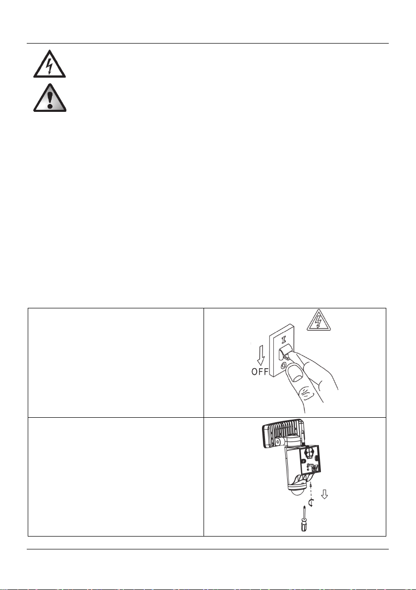
The outdoor camera must be wall-mounted.
Disconnect the power supply.
Undo the mounting plate (10) from the outdoor
camera by removing the screw (11) using the
screwdriver (B).
10 - English
Page 13
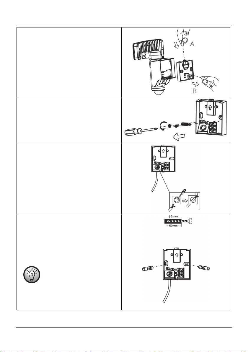
Now press the catch (9) on the mounting plate
(10) and pull the mounting plate (10) on the
strap out of the housing of the outdoor camera.
Remove the 2 screws and then remove the strain
relief.
Punch the rubber seal on the cable feed (e.g.
with a screwdriver) and then push the prepared
power cable through from behind.
WAL 14 A1
Drill through the pre-punched mounting holes
and then draw the position of the drill holes on
the wall in order to drill holes in the wall. To
prevent theft and ensure optimum surveillance of
the area, we recommend a mounting height of
approx. 2.5 metres. Fit the dowels into the
drilled holes.
As an alternative to the approach
described above, the fold-out
page at the end of these
operating instructions contains a
drill template for the exact
positioning of the drill holes.
English - 11
Page 14
WAL 14 A1
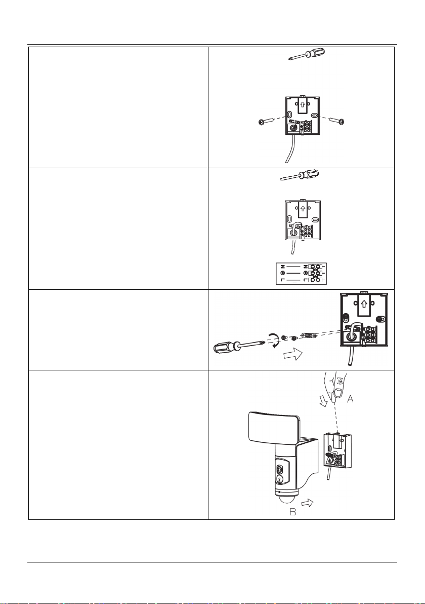
Now screw in the screws to fix the mounting
plate (10) securely to the wall.
Now properly wire the power cable to the
connection terminal on the mounting plate (10).
Note the labelling of the individual terminals.
Then fix the cable by fitting the strain relief with
the 2 screws.
Place the outdoor camera straight on the
mounting plate (10). Press the catch (9) down
and push the outdoor camera towards the wall
until the catch (9) slots into the recess in the
camera housing.
12 - English
Page 15
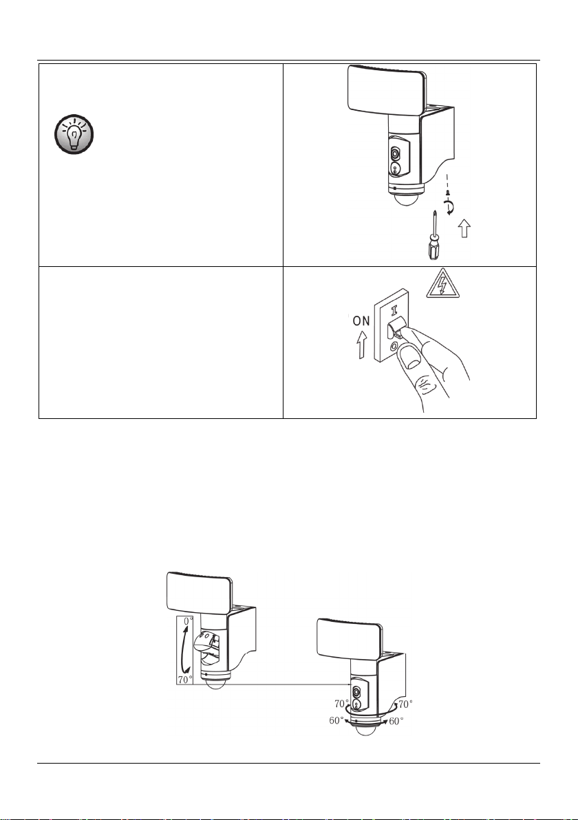
Finally, use the screwdriver (B) to turn the screw
(11) from underneath through the camera
housing into the mounting plate (10).
The screw (11) is a special screw
to guarantee extra protection
against theft. Always use this
screw! It is imperative that the
screw (11) is fitted to prevent theft
of the whole camera body.
Switch the power supply back on again.
WAL 14 A1
7.5. Setting up the LED emitter, camera and movement sensor
You can adjust the camera (3), the LED emitter (1) and the movement sensor (7) to your requirements
independently of one another:
The LED emitter (1) can be swivelled and tilted, the camera (3) swivels and tilts up and down, the
movement sensor (7) swivels.
Use the adjuster ring (6) to adjust the horizontal detection range of the movement sensor.
English - 13
Page 16
WAL 14 A1
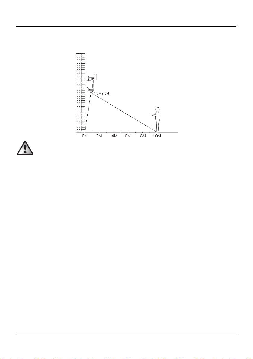
The diagram below gives information on the detection range of the movement sensor (7). Adjust the
movement sensor (7) so it covers the area you want as best possible. It must not be blocked by objects or
similar.
Make sure there are no movements which are not to be detected within the detection range of
the movement sensor (7) (e.g. pavements, roads).
14 - English
Page 17
WAL 14 A1
8. Getting started
For reasons of IT security, please note the following:
Never commission multiple WiFi cameras at the same time and install them in the control app!
Each WiFi camera must be commissioned separately and added to the control app. Only ever
connect one camera per scan. Start a separate scan for each new camera.
8.1. Inserting / removing the memory card
Please note that all the functions of the WiFi camera can only be guaranteed if a Micro SD card
meeting the following specifications is inserted:
Maximum capacity: 128GB, Class 10
The recordings from the camera (3) are saved to a Micro SD card (not included).
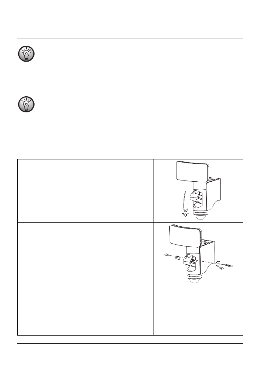
The SD card slot is deliberately concealed and not easily accessible in the camera housing. This makes it
difficult for unauthorised persons to remove the SD card. Proceed as follows to insert or replace the SD
card:
Tilt the camera holder (2) by around 70° until it stops.
Remove the screw covering the SD card slot using the
special screwdriver provided.
Remove the cover from the SD card slot.
The SD card slot is directly beneath the cover, still
concealed and protected by a rubber seal. Lift up the
rubber seal to reveal the SD card slot.
Now you can insert or remove the Micro SD card.
When you insert the SD card, make sure the contacts
are facing forwards, using tweezers may help. The SD
card needs to be pushed against the spring until it
locks into the camera.
To remove the SD card, unlock it by pushing against
this spring. Then remove the unlocked SD card from
the SD card slot using tweezers if necessary.
Finally, replace the rubber seal and the cover of the
SD card slot.
English - 15
Page 18
WAL 14 A1
8.2. Downloading and installing the control app
The outdoor camera is operated using the control app L-Guard HD, which you must install on your
smartphone or tablet. The app is free to download from the relevant app store.
8.2.1. Operating instructions for the control app
Up-to-date operating instructions for the control app can be downloaded in various languages from the
links below. Either use the QR code or enter the address next to it into your browser.
Android
iOS
Android
iOS
Android
https://www.targa.de/downloads/IAN284704/Android_DE.pdf
https://www.targa.de/downloads/IAN284704/iOS_DE.pdf
https://www.targa.de/downloads/IAN284704/Android_GB.pdf
https://www.targa.de/downloads/IAN284704/iOS_GB.pdf
https://www.targa.de/downloads/IAN284704/Android_FR.pdf
iOS
16 - English
https://www.targa.de/downloads/IAN284704/iOS_FR.pdf
Page 19
WAL 14 A1
Android
iOS
Android
iOS
Android
https://www.targa.de/downloads/IAN284704/Android_NL.pdf
https://www.targa.de/downloads/IAN284704/iOS_NL.pdf
https://www.targa.de/downloads/IAN284704/Android_CZ.pdf
https://www.targa.de/downloads/IAN284704/iOS_CZ.pdf
https://www.targa.de/downloads/IAN284704/Android_ES.pdf
iOS
Android
iOS
https://www.targa.de/downloads/IAN284704/iOS_ES.pdf
https://www.targa.de/downloads/IAN284704/Android_PT.pdf
https://www.targa.de/downloads/IAN284704/iOS_PT.pdf
English - 17
Page 20
WAL 14 A1
Android
iOS
Android
iOS
Android
https://www.targa.de/downloads/IAN284704/Android_SI.pdf
https://www.targa.de/downloads/IAN284704/iOS_SI.pdf
https://www.targa.de/downloads/IAN284704/Android_IT.pdf
https://www.targa.de/downloads/IAN284704/iOS_IT.pdf
https://www.targa.de/downloads/IAN284704/Android_DK.pdf
iOS
https://www.targa.de/downloads/IAN284704/iOS_DK.pdf
18 - English
Page 21
WAL 14 A1
8.3. Access data (camera name / password)
To set up the outdoor camera, you need to assign a camera name (to allow unique identification in the
network), a username and a password.
For reasons of IT security, the username and password are transmitted encrypted for communication with
the WiFi outdoor camera.
8.3.1. Camera name
Ideally, you should select a camera name which describes the area monitored.
Example camera names: Rear entrance or Garage door
8.3.2. Username
The username must have at least 8 to 10 characters. These should consist of upper and lower case letters
with one optional special character and one or more numbers.
8.3.3. Password
A secure password helps protect your personal data. Take a little time to develop a secure
password that you should also be able to remember well. Avoid personal data such as your
date of birth or the names of your children or pets. Or sequences of numbers or letters which
are easy to remember but also easy to guess. Also, avoid using the same password more than
once, as this could jeopardise multiple applications if the password is discovered.
A secure password should consist of at least 10 to 12 characters. It should include upper and lower case
letters, numbers and special characters.
Example password: 32Pq!nK65?56
For the outdoor camera, the password must be at lest 10 characters long or an error message is
displayed.
8.3.4. Applying the app settings
For operational safety, we recommend you to close and re-launch the app after you have made any
changes to the app settings.
English - 19
Page 22
WAL 14 A1
8.4. Restoring factory settings
The RESET button on the outdoor camera is deliberately concealed to prevent misuse by unauthorised
persons.
If you have forgotten your password or you wish to restore the factory settings on the outdoor camera for
another reason, proceed as follows:
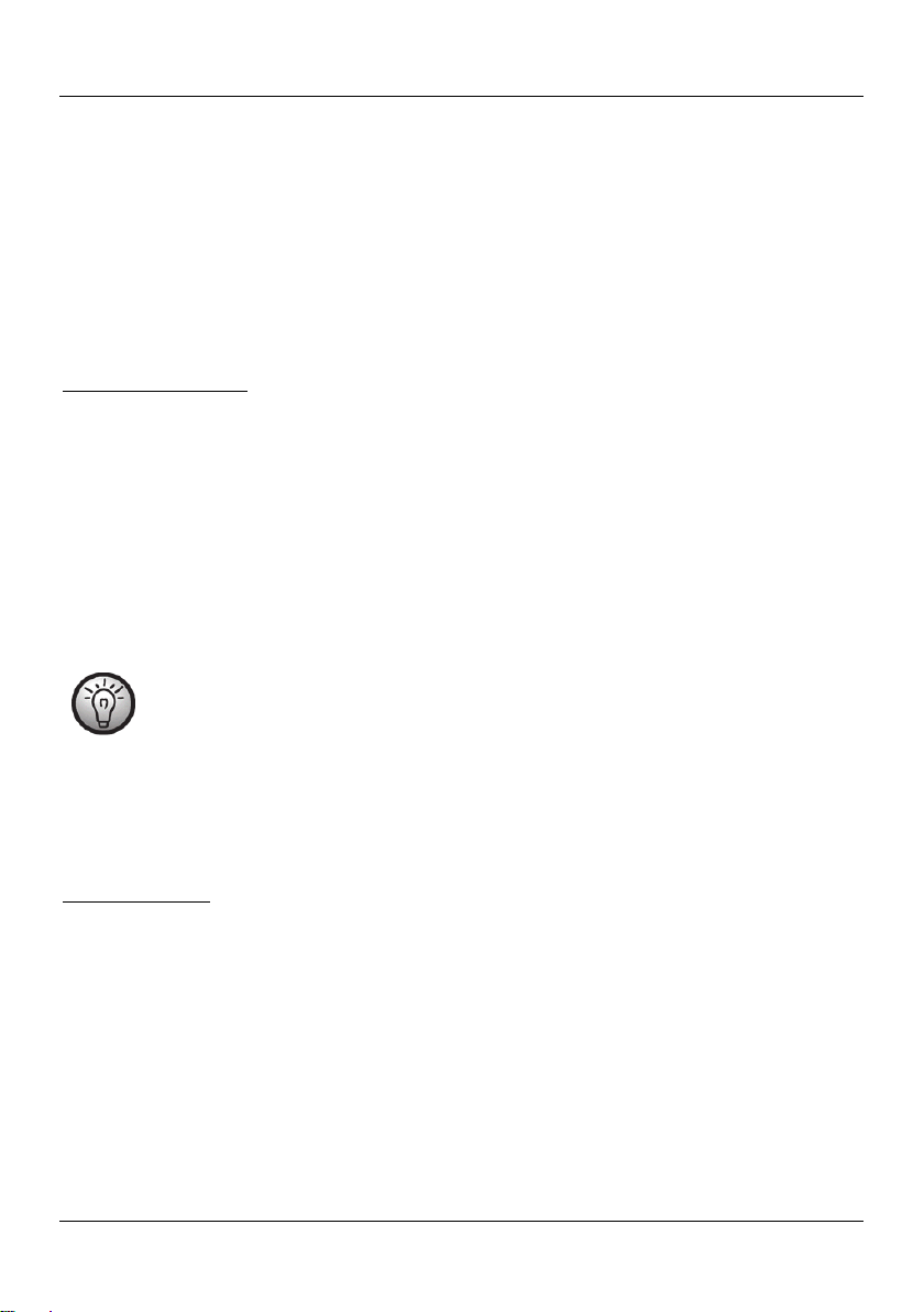
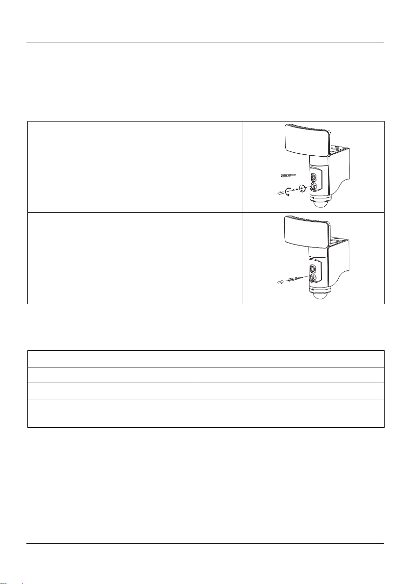
The screw in the centre of the cover of the RESET
button (4) is covered by a rubber bung. Remove this
with a sharp object such as a small screwdriver.
Now undo the screw in the cover (4) using the special
screwdriver and lift the cover (4) off.
The RESET button can be found in the opening
exposed above the screw thread.
To press the RESET button, push the tip of the special
screwdriver into the opening until you feel it switch.
Press and hold the button down for approx. 10
seconds.
The power LED (5) flashes quickly in red.
8.5. LED displays
LED display Description
LED flashing quickly in red* Device ready for network setup
LED flashing green Network connection established
LED flashes green every 2 seconds for
approx. 2 seconds
*On first setup, the LED (5) flashes quickly in red. If this is not the case, this status can be restored at any
time by pressing the RESET button for about 10 seconds.
20 - English
Device is working normally
Page 23

WAL 14 A1
9. Maintenance/cleaning
Maintenance
The outdoor camera does not contain any parts that require maintenance.
Cleaning
DANGER! The mains power must be switched off for all work on the outdoor camera, even
cleaning! Otherwise there is a risk of electric shock!
DANGER! Make sure that no liquid gets into the housing of the outdoor camera. Otherwise
there is a risk of electric shock.
Occasionally, clean the white cover of the LED emitter (1) with a soft, damp cloth to achieve the best
lighting.
To guarantee a consistently good image quality, keep the camera unit (3) on the outdoor camera clean.
Only use a soft cloth and glass cleaner to clean the camera lens.
Never use abrasive detergents or those containing solvents, nor hard brushes or sponges which could
scratch the surface.
10. Troubleshooting
The light does not come on
The movement sensor (7) is not aimed correctly. Correct the positioning.
The electrical connection is faulty. Get the electrical connection checked by an electrician.
The light switches on and off quickly
There is interference to the sensor from other light sources or bright reflective surfaces. Remove the
external light source or reflective surface.
The light does not switch off
There are people or moving objects in the detection range of the movement sensor (7). Remove them.
The outdoor camera is moving in the wind, which is constantly triggering the movement sensor (7).
Always secure the outdoor camera to a stable mounting point.
Faulty recordings / No recordings
Faulty recordings of various kinds can be linked to a faulty Micro SD card. Therefore, if your
recordings are faulty, try putting a Micro SD card that you know works in the camera. The procedure
is the same if there are no recordings.
English - 21
Page 24

WAL 14 A1
Please format the Micro SD card immediately after inserting it into the camera. For manual formatting,
the camera hast to be installed and it has to be connected to the app. After this, trigger the alarm a
few times to check if the recordings are properly saved on the Micro SD card.
11. Environmental regulations and disposal information
A symbol depicting a crossed-out rubbish bin on a product means it is subject to
European Directive 2012/19/EU. All electrical and electronic devices must be
disposed of separately from household waste at official disposal centres. Lamps must
also be disposed of properly.
Do not dispose of the device in household waste or bulky waste collections.
Information on collection points and pick-up times can be obtained from your local
council or waste disposal company.
Dispose of all packaging in an environmentally friendly manner. Cardboard packaging can be taken to
paper recycling centres or public collection points for recycling. Any film or plastic contained in the
packaging should be taken to your public collection points for disposal.
12. EU Declaration of Conformity Notice
This device complies with the basic and other relevant requirements of the RE
Directive 2014/53/EU, the ErP Directive 2009/125/EC and the RoHS Directive
2011/65/EU.
The complete EU Declaration of Conformity is available for download from this link:
www.targa.de/downloads/conformity/284704.pdf
22 - English
Page 25

WAL 14 A1
13. Warranty and servicing advice
Warranty of TARGA GmbH
Dear Customer,
This device is sold with three years warranty from the date of purchase. In the event of product defects,
you have legal rights towards the seller. These statutory rights are not restricted by our warranty as
described below.
Warranty conditions
The warranty period commences upon the date of purchase. Please keep the original receipt in a safe
place as it is required as proof of purchase. If any material or manufacturing faults occur within three
years of purchase of this product, we will repair or replace the product free of charge as we deem
appropriate.
Warranty period and legal warranty rights
The warranty period is not extended in the event of a warranty claim. This also applies to replaced and
repaired parts. Any damage or defects discovered upon purchase must be reported immediately when the
product has been unpacked. Any repairs required after the warranty period will be subject to charge.
Scope of warranty
The device was carefully manufactured in compliance with stringent quality guidelines and subjected to
thorough testing before it left the works. The warranty applies to material and manufacturing faults. This
warranty does not cover product components which are subject to normal wear and which can therefore
be regarded as wearing parts, or damage to fragile components such as switches, rechargeable batteries
or components made of glass. This warranty is void if the product is damaged, incorrectly used or
serviced. To ensure correct use of the product, always comply fully with all instructions contained in the
user manual. The warnings and recommendations in the user manual regarding correct and incorrect use
and handling of the product must always be observed and complied with. The product is solely designed
for private use and is not suitable for commercial applications. The warranty is rendered void in the event
of incorrect handling and misuse, if it is subjected to force, and also if any person other than our
authorised service technicians interfere with the device. No new warranty period commences if the
product is repaired or replaced.
Submitting warranty claims
To ensure speedy handling of your complaint, please note the following:
- Before using your product for the first time, please read the enclosed documentation carefully.
Should any problems arise which cannot be solved in this way, please call our hotline.
- Always have your receipt, the product article number as well as the serial number (if available)
to hand as proof of purchase.
- If it is not possible to solve the problem on the phone, our hotline support staff will initiate further
servicing procedures depending on the fault.
English - 23
Page 26

WAL 14 A1
Service
E-Mail: service.GB@targa-online.com
E-Mail: service.IE@targa-online.com
E-Mail: service.MT@targa-online.com
E-Mail: service.CY@targa-online.com
IAN: 284704
Manufacturer
Please note that the following address is not a service address. First contact the service point stated above.
TARGA GmbH
Coesterweg 45
DE-59494 Soest
GERMANY
Phone: 020 – 70 49 04 03
Phone: 01 - 4370121
Phone: 027 78 11 03
Phone: 02 – 20 09 025
24 - English
Page 27

WAL 14 A1
Indhold
1. Tilsigtet brug ......................................................................................................... 26
2. Varemærkeoplysninger ....................................................................................... 26
3. Pakkens indhold ................................................................................................... 27
4. Tekniske specifikationer ....................................................................................... 28
5. Sikkerhedsanvisninger ......................................................................................... 29
5.1. Overtrædelse af tredjemandsrettigheder / Rettigheder til egne billeder ......................................... 30
6. Ophavsret ............................................................................................................ 31
7. Før du går i gang .................................................................................................. 32
7.1. Det rette monteringssted ...................................................................................................................... 32
7.2. Påkrævet værktøj .................................................................................................................................. 32
7.3. Inden montering .................................................................................................................................... 32
7.4. Montering ............................................................................................................................................. 33
7.5. Indstilling af LED-lampen, kameraet og bevægelsessensoren ........................................................... 36
8. Kom godt i gang ................................................................................................... 37
8.1. Isætning/udtagning af hukommelseskort ............................................................................................ 37
8.2. Hentning og installation af kontrolappen ........................................................................................... 39
8.2.1. Betjeningsvejledning til kontrolappen ......................................................................................... 39
8.3. Adgangsdata (kameranavn/adgangskode) ...................................................................................... 42
8.3.1. Kameranavn ................................................................................................................................. 42
8.3.2. Brugernavn ................................................................................................................................... 42
8.3.3. Adgangskode ............................................................................................................................... 42
8.3.4. Anvendelse af app-indstillingerne ............................................................................................... 42
8.4. Gendannelse af fabriksindstillingerne ................................................................................................. 43
8.5. LED-tilstande .......................................................................................................................................... 43
9. Vedligeholdelse/rengøring .................................................................................. 43
10. Fejlfinding ........................................................................................................... 44
11. Miljøregler og oplysninger om bortskaffelse ...................................................... 45
12. Bemærkning til EU-konformitetserklæring .......................................................... 45
13. Garanti- og serviceoplysninger ........................................................................... 46
Dansk - 25
Page 28

WAL 14 A1
Tillykke!
Ved at købe WiFi-udendørskamera WAL 14 A1 har du valgt et kvalitetsprodukt.
Før du tager det i brug første gang, skal du gøre dig bekendt med, hvordan udendørskameraet fungerer
og læse denne betjeningsvejledning grundigt. Vær omhyggelig med at følge sikkerhedsinstruktionerne, og
brug kun udendørskameraet som beskrevet i betjeningsvejledningen og til de anførte formål.
Opbevar denne betjeningsvejledning i nærheden af produktet med henblik på senere opslag. Hvis du
giver udendørskameraet videre til andre personer, skal du sørge for at vedlægge alle de relevante
dokumenter.
1. Tilsigtet brug
WiFi-udendørskameraet WAL 14 A1 er en elektronisk informationsenhed, som er udviklet til automatisk
overvågning af arealer indendørs og udendørs. Hvor sigtbarheden er dårlig, kan LED-lampen tændes for
at oplyse overvågningsarealet. Udendørskameraet er kun egnet til permanent montering (vægmontering).
Strømforsyningen skal foregå via det elektriske kredsløb i bygningen. Det er ikke beregnet til kommerciel
brug. Denne enhed overholder alle standarder og direktiver, der er anført i
overensstemmelseserklæringen. Alle ændringer på udendørskameraet, ud over dem som anbefales af
producenten, kan resultere i, at apparatet ikke længere lever op til disse standarder.
2. Varemærkeoplysninger
Apple®, iPhone® og iPad® er registrerede varemærker, App Store er et servicemærke, der tilhører Apple
Inc., der er registreret i USA og andre lande.
®
Google
Andre navne og produkter kan være varemærker eller registrerede varemærker tilhørende deres
respektive ejere.
26 - Dansk
og Android® er registrerede varemærker tilhørende Google Inc.
Page 29

3. Pakkens indhold
A WiFi-udendørskamera WAL 14 A1
B Specialskruetrækker
C 2x skruer, 4 x 40 mm
D 2x rawlplugs, 6 x 27 mm
E Denne betjeningsvejledning (stregtegning)
WAL 14 A1
Denne betjeningsvejledning har en flap på omslaget, der kan foldes ud. På indersiden af omslaget er
udendørskameraet vist med talangivelser. De forskellige numre betyder følgende:
1 LED-lampe
2 Kameraholder
3 Kamera
4 Dæksel til RESET-knappen
5 Strøm-LED (viser forskellige driftsstatusser)
6 Justeringsring (til vandret justering af kameraet og bevægelsessensoren)
7 Bevægelsessensor
8 WiFi-antenne
9 Lås (til monteringsplade)
10 Monteringsplade
11 Skrue (til at fastgøre kameraet)
Dansk - 27
Page 30

WAL 14 A1
4. Tekniske specifikationer
Mærkepladen til udendørskamera er angivet på monteringspladen (10).
LED-lampe
Modelnavn: WAL 14 A1
Driftsspænding: 220 – 240 V~, 50 Hz
Samlet strømforbrug: ca. 20 Watt
Strømforbrug fra lys uden
hjælpeenheder:
Lys: 28 LED'er med 0,5 W for hver
Lumen flux: ca. 1250 lumen
Farvetemperatur: ca. 5.000K
Energieffektivitetsklasse for LED-lampe: A+
Justering af lystid:
Til bevægelsessensor:
Manuel indstilling:
Maks. dækningsområde: ca. 50 m², hvis monteret ved en højde på ca. 2,50 m
Driftsposition: Lodret – LED-lampe øverst, bevægelsessensor under den
Omgivende temperatur: -33 °C - + 40 °C
Sikkerhedsklasse: I (med jordledningsforbindelse)
Sikringsgrad: IP54
Mål (W x D x H): ca. 179 x 165 x 256 mm
Vægt: ca. 920 g
Kamera:
Opløsning: 1280*720 pixler
Opdateringshastighed: 1-20 billeder pr. sekund (justerbare)
Synsvinkel: ca. 94° vandret, ca. 48° lodret
Micro SD-kort (ikke inkluderet): Klasse 10, maks. 128 GB
Bevægelsessensor:
Bevægelsessensorvinkel: maks. 180°
Sensorrækkevidde: maks. 10 m
Lysfølsomhed: justerbar via appen
Drejeskive (mekanisk): ca. 120° vandret
WiFi/Kontrolapp L-Guard HD
WiFi-standard: 802.11 b / g / n
WiFi-frekvensbånd: 2,4 GHz
WiFi-transmissionskraft: ca. 8,7 mW
Kompatibilitet for App: iOS 8.0 (og højere) / Android 4.4 (og højere)
De tekniske data og designet kan ændres uden varsel.
ca. 18 Watt
ca. 10 sek. (+/- 5 sek.) til ca. 20 min. (+/- 5 min.)
3 timer, 6 timer eller kontinuerlig, når det er mørkt
(justerbar med tusmørkesensor)
28 - Dansk
Page 31

WAL 14 A1
5. Sikkerhedsanvisninger
Før du tager dette apparat i brug første gang, bedes du læse nedenstående anvisninger og overholde
alle advarsler, også selvom du i forvejen er fortrolig med at håndtere elektroniske enheder. Opbevar
denne betjeningsvejledning på et sikkert sted til fremtidig brug. Hvis du sælger apparatet eller giver det
videre, er det yderst vigtigt, at du også videregiver denne betjeningsvejledning, da den er en del af
produktet.
FARE! Dette symbol og ordet "Fare" advarer dig om en potentielt farlig situation.
Hvis den ignoreres, kan det medføre alvorlige kvæstelser eller dødsfald.
ADVARSEL! Dette symbol og teksten "ADVARSEL" angiver vigtige oplysninger for
sikker brug af produktet og for brugerens sikkerhed.
FARE! Dette symbol angiver sikkerhedsfarer og risiko for dødsfald og/eller for
skade på udstyr grundet elektrisk stød.
Dette symbol angiver, at der er yderligere oplysninger om emnet.
Udendørskameraet har en jordledningsforbindelse. Jordledningen (gul/grøn) skal
tilsluttes til den viste klemme.
Betydningen af IP54-beskyttelse:
WiFi-udendørskameraet er beskyttet mod støv på skadelige niveauer og mod vandstænk fra alle
sider.
FARE! Elektriske apparater er ikke egnede til børn. Lad aldrig børn anvende elektriske
apparater uden opsyn. Børn kan muligvis ikke forstå, at de kan være farlige. Opbevar al
emballage uden for børns rækkevidde. Risiko for kvælning!
FARE! Udendørskameraet skal tilsluttes til en netspænding på 230 V af en kvalificeret elektriker.
Udendørskameraet er i overensstemmelse med Sikkerhedsklasse I, hvilket betyder, at
jordledningen altid skal være forbundet til kameraet.
FARE! Hvis du bemærker røg eller underlige lyde eller lugte fra enheden, skal du afbryde
strømmen til apparatet med det samme ved at slå hovedafbryderen fra til position "0". Hvis dette
sker, bør apparatet ikke bruges længere, og den bør efterses af autoriseret servicepersonale. Du
må ikke indånde røg fra en mulig brand i apparatet. Hvis du ved et uheld indånder røg, skal du
søge læge. Indånding af røg kan være skadeligt for helbredet.
Dansk - 29
Page 32

WAL 14 A1
FARE! Huset til udendørskameraet må ikke beskadiges. Hvis huset åbnes, er der risiko for
elektrisk stød.
FARE! Du må ikke bruge udendørskameraet i omgivelser med en høj risiko for eksplosion fra
brandfarlige gasser, dampe eller støv. Der er fare for eksplosion.
FARE! Huset til udendørskameraet må aldrig åbnes, med undtagelse af når hukommelseskortet
udskiftes. Strømmen skal altid afbrydes, når der udføres arbejde på udendørskameraet, også når
hukommelseskortet udskiftes! Hvis huset åbnes, er der fare for elektrisk stød.
FARE! Risiko for personskade! Anvend aldrig optiske objekter, såsom forstørrelsesglas, til at se
direkte ind i lyset med. Det kan skade dine øjne. Hvis du har mistanke om, at du har beskadiget
dine øjne, skal du søge læge.
FARE! Brandfare! Udendørskameraet må aldrig tildækkes, da det kan få det til at overophede.
FARE! Alle reparationer skal udføres af en specialist.
ADVARSEL! Du må ikke hænge noget på udendørskameraet. Huset er ikke beregnet til at
bære anden vægt. Dette kan beskadige udendørskameraet.
ADVARSEL! Der må ikke stikkes fremmedlegemer ind i udendørskameraet. Dette kan
beskadige udendørskameraet.
5.1. Overtrædelse af tredjemandsrettigheder / Rettigheder til egne
billeder
Rettigheder til at eje billeder eller fotografier er en del af lovgivningen om beskyttelse af persondata.
Denne foreskriver, at enhver person har fundamental ret til at afgøre, om og i hvilken sammenhæng
billeder af dem må offentliggøres.
Private overvågningskameraer (fx IP-kameraer) må ikke bruges til at overvåge offentlige arealer eller
private arealer, som tilhører andre. Dette gælder også fællesarealer (fx en andels- eller lejebolig). Dette
betyder for eksempel indgangsarealer eller stier, der bruges af flere mennesker.
Hvad kan jeg overvåge med mit IP-kamera?
Videoovervågning med et IP-kamera er tilladt på din egen ejendom.
En begrænsning: Alle personer, som berøres af eller kan blive berørt af videoovervågningen, skal
informeres om, at overvågningen finder sted. For at overholde denne forpligtelse anbefales det at påsætte
advarselsskilte eller -mærkater i det område, der overvåges. Imidlertid skal disse advarsler være synlige,
før man går ind i det overvågede område. Hvis man for eksempel overvåger sin ejendom med et IPkamera, skal der gives besked ved indgangen til ejendommen.
Når man opsætter et IP-kamera, bedes man være opmærksom på følgende:
30 - Dansk
Page 33

WAL 14 A1
Ophavsret:
Grundlæggende har enhver person rettigheder over sit eget billede. I henhold til loven om ophavsret kan
billederne kun udgives uden samtykke fra billederne på dem, hvis de blev taget tilfældigt ved siden af et
landemærke eller lignende sted. Hvorvidt en persons ophold kan kaldes for tilfældigt, afhænger af
omstændighederne i det enkelte tilfælde. For at det kan regnes for lovmæssigt forsvarligt, skal
advarselsskiltene anbringes på steder, hvor optagelser af identificerbare personer kan forekomme.
Beskyttelse af privatlivets fred
De viste billeder må ikke krænke privatlivets fred hos andre mennesker. Du må aldrig rette kameraet mod
haven eller hoveddøren til din nabos hjem, heller ikke selvom disse steder er synlige fra dit eget hjem eller
fra offentlige steder. Dette giver dig ikke ret til at offentliggøre disse udsyn. Hvis du er i tvivl, er du nødt til
at begrænse IP-kameraets synsvinkel med en afskærmning.
Personbestemmelse
Personbestemmelse er, hvor en bestemt person kan fastslås at have befundet sig på et bestemt sted på et
bestemt tidspunkt. Identifikationen kan også baseres på personligt identificerbare oplysninger, såsom en
nummerplade. Personbestemmelse skal til hver en tid undgås.
Lovbestemmelserne kan være forskellige fra land til land. Vær opmærksom på bestemmelserne og lovene i
brugslandet.
6. Ophavsret
Alt indholdet i denne betjeningsvejledning er beskyttet af ophavsret og er kun beregnet til information for
brugeren. Kopiering af data og oplysninger uden forudgående udtrykkelig, skriftlig tilladelse fra
forfatteren er strengt forbudt. Det gælder også for enhver kommerciel brug af indholdet og oplysningerne.
Al tekst og alle diagrammer var opdaterede på trykkedatoen. Indholdet kan ændres uden varsel.
Dansk - 31
Page 34

WAL 14 A1
7. Før du går i gang
Fjern udendørskameraet og monteringsdelene fra emballagen.
Kontroller udendørskameraet for skader. Hvis udendørskameraet er beskadiget, må det ikke anvendes.
Hvis leverancen er beskadiget eller ufuldstændig, skal man kontakte producentens kundeservice.
7.1. Det rette monteringssted
Når du vælger et monteringssted, skal du sørge for, at kameraet er monteret
inden for WiFi-netværkets rækkevidde. Hvis det er nødvendigt, kan du bruge
en smartphone eller en tablet til at teste den.
Vælg omhyggeligt en lokalitet, og forbered dig, inden installationen.
Anbring alle de enkelte dele, værktøj og monteringsdele, så du har det hele for hånden.
Udendørskameraet må kun monteres på stabile flader, såsom vægge.
Strømforsyningen kan foregå via det elektriske kredsløb i bygningen.
Undgå at montere udendørskameraet over en varmekilde eller i nærheden af andre lyskilder.
Vælg en placering, hvor udendørskameraet er beskyttet mod vind, regn og snavs.
Find ud af på forhånd, hvilke dele der passer til det sted, du har valgt. Egnede monteringsdele til
beton medfølger.
7.2. Påkrævet værktøj
Følgende værktøjer medfølger ikke. Denne liste er kun vejledende. Det værktøj, du skal bruge, vil afhænge
af den enkelte placering.
Stige
Spændingsafprøver
Vaterpas, foldelineal, blyant
Boremaskine og bor
Phillips skruetrækker, kærvskruetrækker
Kombinationspincetter, knibtænger
7.3. Inden montering
FARE! Enheden skal monteres af en autoriseret el-montør! Strømforsyningen kan foregå via
det elektriske kredsløb i bygningen.
32 - Dansk
Page 35

WAL 14 A1
FARE! Strømmen skal slås fra under monteringen!
ADVARSEL! Når der bores huller, skal det sikres, at der ikke er kabler i væggen.
Inden du monterer udendørskameraet, skal du sørge for, at du er bekendt med alle de enkelte dele,
og læse og følge anvisninger og diagrammer i denne betjeningsvejledning.
Sørg for, at ledningen, som udendørskameraet tilsluttes til, ikke er strømførende. Dette gøres ved at
fjerne sikringen til det relevante strømkredsløb eller skifte effektafbryderen til positionen "0" i
sikringskassen.
Sørg også for at teste, at ledningen ikke er strømførende med en spændingsafprøver!
7.4. Montering
Udendørskameraet skal monteres på en væg.
Afbryd strømforsyningen.
Skru monteringspladen (10) løs fra
udendørskameraet ved at fjerne skruen (11) ved
hjælp af skruetrækkeren (B).
Dansk - 33
Page 36

WAL 14 A1
Tryk på låsen (9) på monteringspladen (10), og
træk monteringspladen (10) i remmen fri af
udendørskameraets hus.
Fjern de 2 skruer, og fjern trækaflastningen.
Fjern gummiforseglingen fra ledningsgangen (fx
med en skruetrækker), og før den klargjorte
strømledning igennem bagfra.
Bor igennem de forborede monteringshuller, og
tegn positionen for borede huller af på væggen,
så der kan bores tilsvarende huller i væggen.
For at forhindre tyveri og sikre optimal
overvågning af området anbefaler vi en
monteringshøjde på ca. 2,5 meter. Indsæt
rawlplugs i de borede huller.
Man kan i stedet for ovennævnte
fremgangsmåde bruge den foldud-side bagest i denne
betjeningsvejledning, som
indeholder en boreskabelon, der
angiver den nøjagtige position for
borehullerne.
34 - Dansk
Page 37

Skru nu skruerne i for at fastgøre
monteringspladen (10) sikkert til væggen.
Forbind derefter strømledningen til klemmerne
på monteringspladen (10). Vær opmærksom på
mærkningen af de enkelte klemmer.
Fastgør ledningen ved at montere
trækaflastningen med de 2 skruer.
WAL 14 A1
Anbring udendørskameraet direkte på
monteringspladen (10). Tryk låsen (9) ned, og
tryk udendørskameraet ind mod væggen, indtil
låsen (9) går i indgreb med profilen på
kamerahuset.
Dansk - 35
Page 38

WAL 14 A1
Brug til slut skruetrækkeren (B) til at skrue skruen
(11) i fra undersiden igennem kamerahuset og
ind i monteringspladen (10).
Skruen (11) er en specialskrue,
hvilket sørger for ekstra
tyverisikring af kameraet. Brug
altid denne skrue! Det er vigtigt,
at skruen (11) skrues i for at
forhindre tyveri af hele
kamerakroppen.
Slå strømforsyningen til igen.
7.5. Indstilling af LED-lampen, kameraet og bevægelsessensoren
Du kan justere kameraet (3), LED-lampen (1) og bevægelsessensoren (7) til dine behov, uafhængigt af
hinanden:
LED-lampen (1) kan drejes og vippes, kameraet (3) drejer og vipper op og ned, bevægelsessensoren
drejer (7).
Brug justeringsringen (6) til at justere det vandrette detektionsområde for bevægelsessensoren.
36 - Dansk
Page 39

WAL 14 A1
Diagrammet nedenfor giver oplysninger om detektionsområdet for bevægelsessensoren (7). Juster
bevægelsessensoren (7), så den dækker det område, du ønsker, bedst muligt. Den må ikke blokeres af
genstande eller lignende.
Sørg for, at der ikke er områder med bevægelse, som ikke skal påvises inden for
bevægelsessensorens (7) detektionsområde (fx fortove, veje).
8. Kom godt i gang
Af hensyn til IT-sikkerheden skal man være opmærksom på følgende:
Undgå at igangsætte flere WiFi-kameraer på samme tid, og tilføje dem alle i kontrolappen!
Hvert WiFi-kamera skal igangsættes separat, og derefter tilføjes i kontrolappen. Tilslut kun et
kamera pr. scanning. Start en separat scanning for hvert nyt kamera.
8.1. Isætning/udtagning af hukommelseskort
Bemærk, at alle funktioner for WiFi-kameraet kun kan garanteres, hvis det indsatte Micro SD-kort
imødekommer følgende specifikationer:
Maksimum kapacitet: 128 GB, Klasse 10
Optagelserne fra kameraet (3) gemmes på et Micro SD-kort (ikke inkluderet).
SD-kortindgangen er med vilje skjult, og ikke nemt tilgængelig på kamerahuset. Dette gør det vanskeligt
for uautoriserede personer at fjerne SD-kortet. Sådan isættes eller udskiftes SD-kortet:
Dansk - 37
Page 40

WAL 14 A1
Vip kameraholderen (2) med ca. 70°, indtil den
stopper.
Fjern skruen, der dækker SD-kortindgangen ved hjælp
af den medfølgende specialskruetrækker.
Fjern dækslet fra SD-kortindgangen.
SD-kortindgangen er lige under dækslet, men skjult og
beskyttet af gummiforseglingen. Løft
gummiforseglingen for at se SD-kortindgangen.
Nu kan du indsætte eller fjerne Micro SD-kortet.
Når du indsætter SD-kortet, skal du sørge for at
kontakterne vender fremad. Brug eventuelt en pincet.
SD-kortet skal skubbes ind mod fjederen, indtil det går
i indgreb med kameraet.
SD-kortet fjernes ved at låse det op, hvilket gøres ved
at trykke det ind mod denne fjeder. Fjern derefter det
oplåste SD-kort fra SD-kortindgangen, eventuelt med
en pincet.
Til sidst påsættes gummiforseglingen og dækslet på
SD-kortindgangen.
38 - Dansk
Page 41

WAL 14 A1
8.2. Hentning og installation af kontrolappen
Udendørskameraet betjenes ved hjælp af kontrolappen L-Guard HD, som du skal installere på din
smartphone eller tablet. Appen er gratis at downloade fra den relevante app store.
8.2.1. Betjeningsvejledning til kontrolappen
Den seneste betjeningsvejledning fra kontrolappen kan downloades på forskellige sprog på linkene
nedenfor. Brug enten QR-koden, eller indtast adressen ved siden af den i din browser.
Android
iOS
Android
iOS
Android
https://www.targa.de/downloads/IAN284704/Android_DE.pdf
https://www.targa.de/downloads/IAN284704/iOS_DE.pdf
https://www.targa.de/downloads/IAN284704/Android_GB.pdf
https://www.targa.de/downloads/IAN284704/iOS_GB.pdf
https://www.targa.de/downloads/IAN284704/Android_FR.pdf
iOS
https://www.targa.de/downloads/IAN284704/iOS_FR.pdf
Dansk - 39
Page 42

WAL 14 A1
Android
iOS
Android
iOS
Android
https://www.targa.de/downloads/IAN284704/Android_NL.pdf
https://www.targa.de/downloads/IAN284704/iOS_NL.pdf
https://www.targa.de/downloads/IAN284704/Android_CZ.pdf
https://www.targa.de/downloads/IAN284704/iOS_CZ.pdf
https://www.targa.de/downloads/IAN284704/Android_ES.pdf
iOS
Android
iOS
40 - Dansk
https://www.targa.de/downloads/IAN284704/iOS_ES.pdf
https://www.targa.de/downloads/IAN284704/Android_PT.pdf
https://www.targa.de/downloads/IAN284704/iOS_PT.pdf
Page 43

WAL 14 A1
Android
iOS
Android
iOS
Android
https://www.targa.de/downloads/IAN284704/Android_SI.pdf
https://www.targa.de/downloads/IAN284704/iOS_SI.pdf
https://www.targa.de/downloads/IAN284704/Android_IT.pdf
https://www.targa.de/downloads/IAN284704/iOS_IT.pdf
https://www.targa.de/downloads/IAN284704/Android_DK.pdf
iOS
https://www.targa.de/downloads/IAN284704/iOS_DK.pdf
Dansk - 41
Page 44

WAL 14 A1
8.3. Adgangsdata (kameranavn/adgangskode)
Udendørskameraet sættes op ved at tilknytte at kameranavn (for at tillade entydig identifikation på
netværket), et brugernavn og en adgangskode.
Af hensyn til IT-sikkerheden vil brugernavnet og adgangskoden blive overført i krypteret form med henblik
på kommunikation med WiFi-udendørskameraet.
8.3.1. Kameranavn
Ideelt set bør du vælge et kameranavn, som beskriver det areal, der overvåges.
Eksempler på kameranavne: Bagindgang eller garagedør
8.3.2. Brugernavn
Brugernavnet skal bestå af mindst 8 til 10 tegn. Disse skal bestå af store og små bogstaver med et
specialtegn og et eller flere tal.
8.3.3. Adgangskode
En sikker adgangskode hjælper med at beskytte dine persondata. Tag dig god tid til at oprette
en sikker adgangskode, som du samtidig er i stand til at huske. Undgå personlige oplysninger,
såsom din fødselsdag eller navne på dine børn eller kæledyr. Undgå også nummersekvenser
eller bogstaver, som er nemme at huske, men også nemme at gætte. Undgå endelig at bruge
samme adgangskode mere end en gang, da dette kan bringe flere applikationer i fare, hvis
adgangskoden opdages.
En sikker adgangskode skal bestå af 10 til 12 tegn. Den skal bestå af store og små bogstaver, tal og
specialtegn.
Eksempel på adgangskode: 32Pq!nK65?56
For udendørskameraet skal adgangskoden bestå af mindst 10 tegn, ellers vises der en fejlmeddelelse.
8.3.4. Anvendelse af app-indstillingerne
Af hensyn til driftssikkerheden anbefaler vi, at du lukker og genstarter appen, efter at du har foretaget
ændringer i app-indstillingerne.
42 - Dansk
Page 45

WAL 14 A1
8.4. Gendannelse af fabriksindstillingerne
RESET-knappen på udendørskameraet er med vilje skjult for at forhindre uautoriserede personer i at
misbruge knappen.
Hvis du har glemt din adgangskode, eller du ønsker at gendanne fabriksindstillingerne til
udendørskameraet af andre grunde, skal du fortsætte som følger:
Skruen i midten af dækslet til RESET-knappen (4) er
dækket af en gummiprop. Fjern denne med en skarp
genstand, fx en lille skruetrækker.
Dernæst skrues skruen i dækslet løs (4) med
specialskruetrækkeren, og dækslet (4) løftes af.
RESET-knappen er at finde i åbningen lige over
skruegevindet.
Tryk på RESET-knappen ved at føre
specialskruetrækkeren ind i åbningen, indtil du
mærker kontakten. Tryk og hold knappen nede i ca.
10 sekunder.
Strøm-LED'en (5) blinker hurtigt rødt.
8.5. LED-tilstande
LED-tilstand Beskrivelse
LED blinker hurtigt rødt* Enheden er klar til netværksopsætning
LED blinker grønt Netværksforbindelsen blev etableret
LED blinker grønt hvert 2. sekund i ca. 2
sekunder
*Ved første opsætning blinker LED (5) hurtigt rødt. Hvis dette ikke er tilfældet, kan denne status
gendannes når som helst ved at trykke på RESET-knappen i omkring 10 sekunder.
Enheden fungerer normalt
9. Vedligeholdelse/rengøring
Vedligeholdelse
Udendørskameraet indeholder ingen dele, som kræver vedligeholdelse.
Dansk - 43
Page 46

WAL 14 A1
Rengøring
FARE! Strømmen skal altid afbrydes, når der udføres arbejde på udendørskameraet, også ved
rengøring! Ellers er der risiko for elektrisk stød!
FARE! Sørg for, at der ikke kommer væske ind i huset på udendørskameraet. Ellers er der
risiko for elektrisk stød.
Fra tid til anden skal man tørre det hvide dæksel på LED-lampen (1) af med den blød, fugtig klud for at
sikre bedst mulig belysning.
En god og ensartet billedkvalitet sikres ved at holde kameraenheden (3) på udendørskameraet ren. Brug
altid en blød klud og glasrens til at rengøre kameraobjektivet.
Brug aldrig slibende midler eller midler, der indeholder opløsningsmiddel, heller ikke stive børster eller
svampe, der kan ridse overfladen.
10. Fejlfinding
Lyset trænger ikke ind
Bevægelsessensoren (7) sigter ikke korrekt. Ret positionen.
Der er fejl i den elektriske forbindelse. Få den elektriske forbindelse tjekket af en elektriker.
Lyset slukker og tænder hurtigt
Der er interferens fra sensoren eller fra andre lyskilder eller andre kraftigt reflekterende overflader.
Fjern den eksterne lyskilde eller reflekterende overflade.
Lyset slukker ikke
Der er personer eller genstande i bevægelse inden for bevægelsessensorens detektionsområde (7).
Fjern dem.
Udendørskameraet flyttes af vinden, som konstant udløser bevægelsessensoren (7). Sørg altid for at
fastgøre udendørskameraet til et stabilt monteringspunkt.
Fejl i optagelserne / Ingen optagelser
Fejl i optagelserne af forskellig art kan skyldes et defekt Micro SD-kort. Hvis der er fejl i dine
optagelser, kan du derfor forsøge at sætte et andet Micro SD-kort, som du ved virker, i kameraet.
Fremgangsmåden er den samme, hvis der ikke er nogen optagelser.
Husk at formatere Micro SD-kortet, straks efter at det er blevet sat i kameraet. Ved manuel formatering
skal kameraet være installeret og forbundet til appen. Derefter skal alarmen udløses nogle gange for
at tjekke, at optagelserne gemmes korrekt på Micro SD-kortet.
44 - Dansk
Page 47

WAL 14 A1
11. Miljøregler og oplysninger om bortskaffelse
Hvis der findes et symbol med en skraldespand med et kryds over på produktet,
betyder det, at produktet er underlagt det Europæiske Direktiv 2012/19/EU. Alle
elektriske og elektroniske apparater skal bortskaffes særskilt fra husholdningsaffald på
officielle genbrugspladser. Pærer skal også bortskaffes korrekt.
Produktet må ikke smides ud sammen med husholdningsaffaldet eller storskrald. Du kan
få oplysninger om nærmeste genbrugsstation eller opsamlingssted hos kommunen.
Bortskaf al emballage på miljørigtig vis. Papemballage kan afleveres i papircontaineren eller på offentlige
afleveringssteder til genvinding. Film og plastik, der findes i emballagen, skal afleveres på den lokale
genbrugsstation til bortskaffelse.
12. Bemærkning til EU-konformitetserklæring
Dette apparat er afprøvet og godkendt for overholdelse af de grundlæggende og
øvrige relevante krav i RE-direktivet 2014/53/EU, ErP-direktiv 2009/125/EC samt
RoHS-direktiv 2011/65/EU.
Den fulde konformitetserklæring kan hentes via dette link:
www.targa.de/downloads/conformity/284704.pdf
Dansk - 45
Page 48

WAL 14 A1
13. Garanti- og serviceoplysninger
TARGA GmbH - Garanti
Kære kunde,
Der er 3 års garanti på dette apparat fra købsdatoen. I tilfælde af mangler ved dette produkt, har du
ifølge loven rettigheder over for sælgeren. Disse rettigheder begrænses ikke af garantien nedenfor.
Garantibetingelser
Garantien træder i kraft fra og med købsdatoen. Opbevar kassebonen omhyggeligt. Denne bon skal
bruges som bevis for købet. Hvis der opstår en materiale- eller fabrikationsfejl på dette produkt inden for 3
år fra købsdatoen, vil produktet, efter vores skøn, blive enten repareret eller udskiftet gratis.
Garantiperiode og juridiske mangelskrav
Garantiperioden forlænges ikke med garantiydelsen. Dette gælder også for udskiftede og reparerede
dele. Vi skal omgående informeres om skader og mangler ved købet, der konstateres umiddelbar efter
udpakningen. Reparationer, der udføres efter garantiperiodens udløb, er betalingspligtige.
Garantiens omfang
Apparatet er produceret efter strenge kvalitetskrav og testet nøje før leveringen. Garantiydelsen omfatter
materiale- eller fabrikationsfejl. Denne garanti omfatter ikke produktdele, der udsættes for normalt slid og
som derfor kan betragtes som sliddele, eller for skader på skrøbelige dele, f.eks. kontakter, batterier eller
dele, der er fremstillet af glas. Denne garanti bortfalder, hvis produktet bliver skadet på grund af ukorrekt
anvendelse eller vedligeholdelse. Alle anvisninger i betjeningsvejledningen skal følges for at sikre, at
produktet anvendes korrekt. Anvendelsesformål og handlinger, der frarådes eller advares om i
betjeningsvejledningen, skal altid undgås. Produktet er udelukkende beregnet til privat brug, og ikke til
erhvervsmæssig brug. Ved misbrug eller ukorrekt behandling, anvendelse af magt eller reparationer, der
ikke er foretaget af vores autoriserede serviceafdeling, bortfalder garantien. Der påbegyndes ikke en ny
garantiperiode ved reparation eller udskiftning af produktet.
Afvikling i tilfælde af garantisager
For at sikre en hurtig behandling af din sag, bedes du følge anvisningerne nedenfor:
- Læs venligst den vedlagte dokumentation omhyggeligt, før du tager dit produkt i brug. Hvis der
skulle opstå et problem, der ikke kan afhjælpes på denne måde, bedes du kontakte vores
hotline.
- Sørg venligst for, at du altid har din kassebon og artikelnummeret, eller i givet fald
serienummeret, parat som købsbevis, når du kontakter os.
- I tilfælde af, at problemet ikke kan afhjælpes via telefonen, foranlediger vi yderligere service
via vores hotline, afhængigt af årsagen til fejlen.
46 - Dansk
Page 49

WAL 14 A1
Service
E-mail: service.DK@targa-online.com
IAN: 284704
Producent
Bemærk venligst, at adressen nedenfor ikke er en serviceadresse. Kontakt først det servicecenter, der er
angivet ovenfor.
TARGA GmbH
Coesterweg 45
DE-59494 Soest
TYSKLAND
Telefon: 078 79 29 87
Dansk - 47
Page 50

WAL 14 A1
Inhalt
1. Bestimmungsgemäße Verwendung ...................................................................... 49
2. Informationen zu Warenzeichen ........................................................................... 49
3. Lieferumfang ........................................................................................................ 50
4. Technische Daten .................................................................................................. 51
5. Sicherheitshinweise .............................................................................................. 52
5.1. Verletzung von Rechten Dritter / Recht am eigenen Bild................................................................... 53
6. Urheberrecht ........................................................................................................ 54
7. Vor der Inbetriebnahme ....................................................................................... 55
7.1. Der richtige Montageort ...................................................................................................................... 55
7.2. Benötigtes Werkzeug ........................................................................................................................... 55
7.3. Vor der Montage.................................................................................................................................. 56
7.4. Montage ............................................................................................................................................... 56
7.5. LED-Strahler, Kamera und Bewegungsmelder ausrichten .................................................................. 59
8. Inbetriebnahme .................................................................................................... 60
8.1. Einlegen / Entnehmen der Speicherkarte ........................................................................................... 60
8.2. Download und Installation der Steuerungs-App ................................................................................ 62
8.2.1. Bedienungsanleitungen für die Steuerungs-App ........................................................................ 62
8.3. Zugangsdaten (Kameraname / Passwort) ......................................................................................... 65
8.3.1. Kameraname ................................................................................................................................ 65
8.3.2. Benutzername .............................................................................................................................. 65
8.3.3. Passwort ........................................................................................................................................ 65
8.3.4. App-Einstellungen übernehmen ................................................................................................... 65
8.4. Werkseinstellung wiederherstellen ...................................................................................................... 66
8.5. LED Anzeigen ....................................................................................................................................... 66
9. Wartung/Reinigung .............................................................................................. 66
10. Problemlösung ................................................................................................... 67
11. Umwelthinweise und Entsorgungsangaben ........................................................ 68
12. Hinweise zur EU-Konformitätserklärung ............................................................. 68
13. Hinweise zu Garantie und Serviceabwicklung .................................................... 69
48 - Deutsch
Page 51

WAL 14 A1
Herzlichen Glückwunsch!
Mit dem Kauf der WLAN Außenkamera WAL 14 A1 haben Sie sich für ein hochwertiges Produkt
entschieden.
Machen Sie sich vor der ersten Inbetriebnahme mit der Außenkamera vertraut und lesen Sie diese
Bedienungsanleitung aufmerksam durch. Beachten Sie vor allem die Sicherheitshinweise und benutzen Sie
die Außenkamera nur, wie in dieser Bedienungsanleitung beschrieben und für die angegebenen
Einsatzbereiche.
Bewahren Sie diese Bedienungsanleitung als späteres Nachschlagewerk in der Nähe des Produktes auf.
Händigen Sie alle Unterlagen bei Weitergabe der Außenkamera an Dritte ebenfalls mit aus.
1. Bestimmungsgemäße Verwendung
Die WLAN Außenkamera WAL 14 A1 ist ein Gerät der Informationselektronik und für die automatische
Überwachung von Innen- und Außenbereichen vorgesehen. Bei schlechten Sichtverhältnissen kann
zusätzlich die LED Beleuchtung zur Ausleuchtung des überwachten Bereiches eingeschaltet werden. Die
Außenkamera darf nur fest montiert (Wandmontage) verwendet werden. Die Spannungsversorgung darf
ausschließlich über die elektrische Anlage des Gebäudes hergestellt werden. Sie ist nicht für den
gewerblichen Einsatz bestimmt. Das Gerät erfüllt alle in der Konformitätserklärung genannten Normen
und Richtlinien. Bei einer nicht mit dem Hersteller abgestimmten Änderung der Außenkamera ist die
Einhaltung dieser Normen nicht mehr gewährleistet.
2. Informationen zu Warenzeichen
Apple®, iPhone® und iPad® sind Warenzeichen, App Store ist eine Dienstleistungsmarke von Apple Inc.,
eingetragen in den U.S.A. und anderen Ländern.
®
Google
Weitere Namen und Produkte können die Warenzeichen bzw. eingetragene Warenzeichen der
jeweiligen Eigentümer sein.
und Android® sind Warenzeichen von Google Inc.
Deutsch - 49
Page 52

WAL 14 A1
3. Lieferumfang
A WLAN Außenkamera WAL 14 A1
B Spezialschraubendreher
C 2 x Schraube 4 x 40mm
D 2 x Dübel 6 x 27mm
E Bedienungsanleitung (Symboldbild)
Diese Bedienungsanleitung ist mit einem ausklappbaren Umschlag versehen. Auf der Innenseite des
Umschlags ist die Außenkamera mit einer Bezifferung abgebildet. Die Ziffern haben folgende Bedeutung:
1 LED-Strahler
2 Kameraträger
3 Kamera
4 Abdeckung RESET-Taster
5 Betriebs-LED (Anzeige diverser Betriebszustände)
6 Einstellring (zur horizontalen Ausrichtung von Kamera und Bewegungsmelder)
7 Bewegungsmelder
8 WLAN-Antenne
9 Verriegelung (für Montageplatte)
10 Montageplatte
11 Schraube (zur Sicherung der Kamera)
50 - Deutsch
Page 53

WAL 14 A1
4. Technische Daten
Das Typenschild der Außenkamera befindet sich an der Montageplatte (10).
LED-Strahler
Modellbezeichnung: WAL 14 A1
Betriebsspannung: 220 – 240 V~, 50 Hz
Leistungsaufnahme gesamt: ca. 20 Watt
Leistungsaufnahme Leuchte ohne
Zusatzgeräte:
Leuchtmittel: 28 LED je 0,5 W
Lichtstrom: ca. 1250 Lumen
Farbtemperatur: ca. 5000K
Energieeffizienzklasse LED-Strahler: A+
Leuchtdauer einstellbar
bei Bewegungserkennung:
manuelle Einstellung:
max. projizierte Lichtfläche: ca. 50m² bei Montage in ca. 2,50m Höhe
Betriebslage: senkrecht – LED-Strahler oben, Bewegungsmelder unten
Umgebungstemperatur ta: -33°C - + 40°C
Schutzklasse: I (mit Schutzleiteranschluss)
Schutzart: IP54
Abmessungen (B x T x H): ca. 179 x 165 x 256 mm
Gewicht: ca. 920 g
Kamera:
Auflösung: 1280*720 Bildpunkte
Bildwiederholrate: 1-20 Bilder pro Sekunde (einstellbar)
Blickwinkel: ca. 94° horizontal, ca. 48° vertikal
Mikro SD-Karte (nicht im Lieferumfang): Class 10, max. 128 Gb
Bewegungsmelder:
Erfassungswinkel Sensor: max. 180°
Erfassungsreichweite: max. 10 m
Lichtempfindlichkeit: über App einstellbar
Drehbar (mechanisch): ca. 120° horizontal
WLAN / Steuerungs-App L-Guard HD
WLAN-Standard: 802.11 b / g / n
WLAN Frequenzbereich: 2,4GHz
WLAN Sendeleistung: ca.8,7 mW
App-Kompatibilität: iOS 8.0 (und höher) / Android 4.4 (und höher)
Änderungen der technischen Daten sowie des Designs können ohne Ankündigung erfolgen.
ca. 18 Watt
ca. 10 Sek. (+/- 5Sek.) bis ca. 20 Min. (+/- 5 Min.)
3 Std., 6 Std. oder Dauerbetrieb bei Dunkelheit (einstellbar
über Dämmerungssensor)
Deutsch - 51
Page 54

WAL 14 A1
5. Sicherheitshinweise
Vor der ersten Verwendung des Gerätes lesen Sie bitte die folgenden Anweisungen genau durch und
beachten Sie alle Warnhinweise, selbst wenn Ihnen der Umgang mit elektronischen Geräten vertraut ist.
Bewahren Sie diese Bedienungsanleitung sorgfältig als zukünftige Referenz auf. Wenn Sie das Gerät
verkaufen oder weitergeben, händigen Sie unbedingt auch diese Bedienungsanleitung aus, sie ist
Bestandteil des Produktes.
GEFAHR! Dieses Symbol, mit dem Hinweis „Gefahr“, kennzeichnet eine drohende
gefährliche Situation, die, wenn Sie nicht verhindert wird, zu schweren Verletzungen
oder sogar zum Tod führen kann.
WARNUNG! Dieses Symbol, mit dem Hinweis „WARNUNG“, kennzeichnet
wichtige Hinweise für den sicheren Betrieb des Gerätes und zum Schutz des
Anwenders.
GEFAHR! Dieses Symbol kennzeichnet Gefahren für die Gesundheit bis zur
Lebensgefahr und/oder Sachschäden durch elektrischen Schlag.
Dieses Symbol kennzeichnet weitere informative Hinweise zum Thema.
Die Außenkamera hat einen Schutzleiteranschluss. Der Schutzleiter (Grün/Gelb)
muss an die gekennzeichnete Klemme angeschlossen werden.
Bedeutung der Schutzart IP54:
Die WLAN-Außenkamera ist geschützt gegen Staub in schädigender Menge und Schutz gegen
allseitiges Spritzwasser.
GEFAHR! Elektrische Geräte gehören nicht in Kinderhände. Lassen Sie Kinder niemals
unbeaufsichtigt elektrische Geräte benutzen. Kinder können mögliche Gefahren nicht immer
richtig erkennen. Halten Sie auch die Verpackungsfolien von Kindern fern. Es besteht
Erstickungsgefahr.
GEFAHR! Die Montage der Außenkamera an das 230 V Stromnetz darf nur durch eine
ausgebildete Elektrofachkraft erfolgen.
Die Außenkamera entspricht der Schutzklasse I, d. h. der Schutzleiter muss in jedem Fall an die
Kamera angeschlossen werden.
GEFAHR! Falls Sie Rauchentwicklung, ungewöhnliche Geräusche oder Gerüche feststellen,
trennen Sie das Gerät sofort vom Stromnetz, indem Sie ggf. die entsprechende Haussicherung
52 - Deutsch
Page 55

WAL 14 A1
herausdrehen bzw. in Stellung „0“ schalten. In diesen Fällen darf das Gerät nicht weiter
verwendet werden, bevor eine Überprüfung durch einen Fachmann durchgeführt wurde. Atmen
Sie keinesfalls Rauch aus einem möglichen Gerätebrand ein. Sollten Sie dennoch Rauch
eingeatmet haben, suchen Sie einen Arzt auf. Das Einatmen von Rauch kann
gesundheitsschädlich sein.
GEFAHR! Das Gehäuse der Außenkamera darf nicht beschädigt werden. Bei beschädigtem
Gehäuse besteht Gefahr durch einen elektrischen Schlag.
GEFAHR! Verwenden Sie die Außenkamera nicht in explosionsgefährdeter Umgebung, in der
sich brennbare Gase, Dämpfe oder Stäube befinden. Es besteht Explosionsgefahr.
GEFAHR! Öffnen Sie niemals das Gehäuse der Außenkamera, außer beim Wechsel der
Speicherkarte. Der Stromkreis muss während aller Arbeiten an der Außenkamera, auch während
des Speicherkartenwechsels, abgeschaltet sein! Bei geöffnetem Gehäuse besteht Gefahr durch
einen elektrischen Schlag.
GEFAHR! Verletzungsgefahr! Benutzen Sie keinesfalls optische Instrumente, wie zum Beispiel
ein Vergrößerungsglas, um direkt in den Lichtstrahl zu schauen. Dies kann zu Augenschäden
führen. Bei Verdacht auf Augenschäden suchen Sie sofort einen Arzt auf.
GEFAHR! Brandgefahr! Die Außenkamera darf niemals abgedeckt werden, da sich diese
ansonsten erwärmt.
GEFAHR! Reparaturen dürfen nur durch eine Fachkraft ausgeführt werden.
WARNUNG! Es dürfen keine Gegenstände an die Außenkamera gehängt werden. Das
Gehäuse ist nicht zum Tragen von Lasten geeignet. Andernfalls könnte die Außenkamera
beschädigt werden.
WARNUNG! Es dürfen kein Fremdkörper in die Außenkamera eingeführt werden. Andernfalls
könnte die Außenkamera beschädigt werden.
5.1. Verletzung von Rechten Dritter / Recht am eigenen Bild
Das Recht am eigenen Bild oder Bildnisrecht ist eine besondere Ausprägung des allgemeinen
Persönlichkeitsrechts. Es besagt, dass jeder Mensch grundsätzlich selbst darüber bestimmen darf, ob und
in welchem Zusammenhang Bilder von ihm veröffentlicht werden.
Private Überwachungskameras (z.B. IP Kameras) dürfen nicht zur Überwachung öffentlicher oder privater
Flächen Dritter eingesetzt werden. Dieses gilt auch für Flächen, die von einer Gemeinschaft (z.B.
Eigentümer- oder Mietergemeinschaft) genutzt werden. Gemeint sind hier beispielsweise
Eingangsbereiche oder Zuwegungen, die von mehreren Personen in Anspruch genommen werden.
Was darf mit einer IP Kamera überwacht werden?
Wenn es nur um die Überwachung des Eigentums geht, ist die Videoüberwachung per IP Kamera in
diesem Fall erlaubt.
Deutsch - 53
Page 56

WAL 14 A1
Einzige Einschränkung: Alle Personen, die von dieser Videoüberwachung betroffen sind bzw. sein können,
müssen über die durchgeführte Überwachung in Kenntnis gesetzt werden. Um dieser Pflicht
nachzukommen ist es ausreichend, Hinweisschilder oder Aufkleber am überwachten Objekt anzubringen.
Diese Hinweise müssen jedoch vor dem Betreten der überwachten Fläche erkennbar sein. Wenn Sie z.B.
Ihr eigenes Grundstück mit einer IP Kamera überwachen, sollten Sie an allen Zugängen einen
entsprechenden Hinweis anbringen.
Beim Einrichten einer IP-Kamera sollten Sie Folgendes beachten:
Urheberschutz:
Grundsätzlich hat jede Person das Recht am eigenen Bild. Nach dem Urheberrechtsgesetz dürfen Bilder
ohne Einwilligung der Betroffenen nur dann veröffentlicht werden, wenn die Personen lediglich als Beiwerk
neben einer Landschaft oder sonstigen Örtlichkeiten erscheinen. Die Beantwortung der Frage, ob eine
Person nur Beiwerk ist, hängt von den Umständen des Einzelfalls ab. Aus Gründen der Rechtssicherheit
sollte in allen Fällen, in denen Aufnahmen mit identifizierbarem Personenbezug möglich sind, über die
Webcam informiert werden, gegebenenfalls mit Hinweisschildern.
Schutz der Privatsphäre
Die Privatsphäre anderer darf durch die gezeigten Bilder nicht verletzt werden. Richten Sie Ihre Kamera
nicht in den Garten oder auf die Eingangstür Ihrer Nachbarwohnung, auch wenn diese Orte aus Ihrer
eigenen Wohnung oder von öffentlichen Standorten einsehbar sind. Dies berechtigt nicht die
Veröffentlichung dieser Einsichten. Im Zweifelsfall müssen Sie das Blickfeld der IP Kamera durch einen
Sichtschutz einschränken.
Personelle Bestimmbarkeit
Eine personelle Bestimmbarkeit liegt vor, wenn festgestellt werden kann, dass eine bestimmte Person zu
einer bestimmten Zeit an einem bestimmten Ort war. Die Identifikation kann dabei auch über ein
personenbezogenes Kennzeichen, wie z.B. das Fahrzeugkennzeichen, erfolgen. Eine personelle
Bestimmbarkeit von Personen ist unbedingt zu vermeiden.
Die rechtlichen Vorgaben können in verschieden Ländern unterschiedlich sein. Bitte beachten Sie die
Gesetze des jeweiligen Einsatzlandes.
6. Urheberrecht
Alle Inhalte dieser Bedienungsanleitung unterliegen dem Urheberrecht und werden dem Leser
ausschließlich als Informationsquelle bereitgestellt. Jegliches Kopieren oder Vervielfältigen von Daten und
Informationen ist ohne ausdrückliche und schriftliche Genehmigung durch den Autor verboten. Dies betrifft
auch die gewerbliche Nutzung der Inhalte und Daten. Text und Abbildungen entsprechen dem
technischen Stand bei Drucklegung. Änderungen vorbehalten.
54 - Deutsch
Page 57

WAL 14 A1
7. Vor der Inbetriebnahme
Entnehmen Sie die Außenkamera und das Montagematerial aus der Verpackung.
Prüfen Sie die Außenkamera auf Beschädigungen. Bei Beschädigungen darf die Außenkamera nicht in
Betrieb genommen werden.
Bitte wenden Sie sich bei defekter oder unvollständiger Lieferung an den Kundendienst des Herstellers.
7.1. Der richtige Montageort
Bitte beachten Sie bei der Auswahl des Montageortes, dass die Kamera
zwingend innerhalb der Reichweite des genutzten WLAN-Netzwerkes
montiert werden muss. Testen Sie dieses gegebenenfalls mit Smartphone oder
Tablet-PC.
Wählen Sie den Montageort sorgfältig aus und bereiten Sie die Montage gut vor.
Legen Sie alle Einzelteile, benötigtes Werkzeug und Montagematerial griffbereit und geordnet
zurecht.
Die Außenkamera darf nur auf stabilen Untergründen, z.B. Mauerwerk montiert werden.
Die Spannungsversorgung darf ausschließlich über die elektrische Anlage des Gebäudes hergestellt
werden.
Montieren Sie die Außenkamera nicht über einer Wärmequelle oder in unmittelbarer Nähe zu
anderen Lichtquellen.
Wählen Sie den Montageort so, dass die Außenkamera vor Wind, Regen und Verschmutzung
geschützt ist.
Informieren Sie sich vorab, welches Montagematerial für den von Ihnen gewählten Montageort
geeignet ist. Der Außenkamera liegt geeignetes Montagematerial für Beton bei.
7.2. Benötigtes Werkzeug
Folgende Werkzeuge sind nicht im Lieferumfang enthalten. Diese Liste dient Ihnen zur Orientierung. Die
genaue Beschaffenheit der benötigten Werkzeuge richtet sich nach den individuellen Gegebenheiten vor
Ort.
Leiter
Spannungsprüfer
Wasserwaage, Gliedermaßstab, Bleistift
Bohrmaschine mit Bohrer
Kreuzschlitzschraubendreher, Schlitzschraubendreher
Kombizange, Seitenschneider
Deutsch - 55
Page 58

WAL 14 A1
7.3. Vor der Montage
GEFAHR! Die Montage darf nur von einer autorisierten Elektrofachkraft durchgeführt
werden! Die Spannungsversorgung darf ausschließlich über die elektrische Anlage des
Gebäudes hergestellt werden.
GEFAHR! Der Stromkreis muss während der Montage abgeschaltet sein!
WARNUNG! Achten Sie beim Bohren der Bohrlöcher darauf, dass keine in der Wand
liegenden Leitungen beschädigt werden.
Vor der Montage machen Sie sich mit den Einzelteilen der Außenkamera, sowie den Anleitungen und
Abbildungen dieser Bedienungsanleitung vertraut und beachten Sie diese.
Stellen Sie sicher, dass die Leitung, an der die Außenkamera angeschlossen werden soll, keine
Spannung führt. Zu diesem Zweck entfernen Sie in Ihrem Sicherungskasten die Sicherung des
entsprechenden Stromkreises, bzw. schalten Sie die Sicherung in Stellung „0“.
Überprüfen Sie die Spannungsfreiheit der Leitung unbedingt zusätzlich mit einem Spannungsprüfer!
7.4. Montage
Die Montage der Außenkamera muss als Wandmontage erfolgen.
Schalten Sie den Stromkreis aus.
Lösen Sie die Montageplatte (10) von der
Außenkamera, indem Sie die Schraube (11) mit
dem Schraubendreher (B) entfernen.
56 - Deutsch
Page 59

Drücken Sie nun die Verriegelung (9) der
Montageplatte (10) nach unten und ziehen Sie
die Montageplatte (10) an dem Zugband aus
dem Gehäuse der Außenkamera heraus.
Entfernen Sie die Zugentlastung, nachdem Sie
die 2 Schrauben entfernt haben.
Durchstechen Sie die Gummidichtung der
Kabeldurchführung (z.B. mit einem
Schraubendreher) und schieben Sie
anschließend das vorbereitete Anschlusskabel
von hinten hindurch.
WAL 14 A1
Durchbohren Sie die vorgestanzten
Montagelöcher und zeichnen Sie anschließend
die Position der Bohrlöcher an der Wand an, um
danach die Wandbohrung durchzuführen. Aus
Gründen des Diebstahlschutzes und für eine
optimale Bereichsüberwachung empfehlen wir
eine Montagehöhe von ca. 2,50 Meter. Setzen
Sie die Dübel in die gebohrten Löcher ein.
Als Alternative zur oben
beschriebenen Vorgehensweise
finden Sie auf der Ausklappseite
am Ende dieser Bedienungsanleitung eine Bohrschablone zur
exakten Positionierung der
Bohrlöcher.
Deutsch - 57
Page 60

WAL 14 A1
Schrauben Sie jetzt die Schrauben ein, um die
Montageplatte (10) sicher an der Wand zu
fixieren.
Verdrahten Sie nun fachgerecht die
Anschlussleitung in der Anschlussklemme an der
Montageplatte (10). Beachten Sie dabei die
Kennzeichnung der einzelnen Klemmen.
Fixeren Sie anschließend das Kabel, indem Sie
die Zugentlastung mit den 2 Schrauben wieder
einsetzen.
Setzen Sie die Außenkamera gerade auf die
Montageplatte (10) auf. Drücken Sie die
Verriegelung (9) herunter und schieben Sie die
Außenkamera in Richtung Wand, bis die
Verriegelung (9) in der Aussparung im
Kameragehäuse einrastet.
58 - Deutsch
Page 61

WAL 14 A1
Drehen Sie als letzten Schritt die Schraube (11)
mit dem Schraubendreher (B) von unten durch
das Kameragehäuse in die Montageplatte (10)
ein.
Bei der Schraube (11) handelt es
sich um eine Spezialschraube, mit
der ein erhöhter Diebstahlschutz
gewährleistet wird. Verwenden
Sie ausschließlich diese
Schraube! Die Schraube (11) ist
zwingend anzubringen, um einem
Diebstahl des kompletten
Kamerakörpers vorzubeugen.
Schalten Sie den Stromkreis wieder ein.
7.5. LED-Strahler, Kamera und Bewegungsmelder ausrichten
Sie haben die Möglichkeit die Kamera (3), den LED-Strahler (1) und den Bewegungsmelder (7)
unabhängig von einander auf Ihre Bedürfnisse einzustellen:
Der LED-Strahler (1) ist drehbar und neigbar, die Kamera (3) ist drehbar und nach oben und unten
schwenkbar, der Bewegungsmelder (7) ist drehbar.
Mithilfe des Einstellringes (6) kann der Erfassungsbereich des Bewegungsmelders horizontal verstellt
werden.
Deutsch - 59
Page 62

WAL 14 A1
A
Folgende Grafik gibt Ihnen Informationen zum Erfassungsbereich des Bewegungsmelders (7). Richten Sie
den Bewegungsmelder (7) so aus, dass dieser den gewünschten Bereich möglichst gut erfassen kann. Die
Sicht darf nicht durch Gegenstände o. ä. behindert werden.
Achten Sie darauf, dass im Erfassungsbereich des Bewegungsmelders (7) keine Bewegungen
vorkommen, die nicht erfasst werden sollen (z.B. Gehwege, Straßen).
8. Inbetriebnahme
Aus Gründen der IT-Sicherheit beachten Sie bitte Folgendes:
Niemals mehrere WLAN-Kameras gleichzeitig in Betrieb nehmen und diese in der SteuerungsApp installieren!
Jede WLAN-Kamera muss separat in Betrieb genommen und in der Steuerungswerden. Binden Sie nur jeweils eine Kamera pro Suchlauf ein. Starten Sie für jede weitere Kamera
einen separaten Suchlauf.
pp hinzugefügt
8.1. Einlegen / Entnehmen der Speicherkarte
Bitte beachten Sie, dass alle Funktionen der WLAN-Kamera nur gewährleistet werden können,
wenn eine Micro-SD-Karte eingelegt ist, die folgenden Spezifikationen entspricht:
maximale Kapazität: 128GB, Class 10
Die Aufzeichnungen der Kamera (3) werden auf einer Micro-SD-Karte (nicht im Lieferumfang enthalten)
gespeichert.
Der SD-Kartenschacht liegt bewusst versteckt und schwer zugänglich am Kameragehäuse. So ist
sichergestellt, dass Unbefugte nicht ohne Aufwand die SD-Karte entfernen können. Beachten Sie zum
Einlegen bzw. Wechseln der SD-Karte die folgende Beschreibung.
60 - Deutsch
Page 63

Neigen Sie den Kameraträger (2) bis zum Anschlag
um ca.70°.
Entfernen Sie die Schraube der Abdeckung des SD-
Kartenschachtes mit dem mitgelieferten
Spezialschraubendreher.
Entfernen Sie die Abdeckung des SD-Kartenschachtes.
Der SD-Kartenschacht liegt direkt unter der
Abdeckung, noch verdeckt und geschützt von einer
Gummidichtung. Ziehen Sie diese Gummidichtung
hoch, um den SD-Kartenschacht freizulegen.
Sie können nun die Micro-SD-Karte einlegen bzw.
entnehmen.
Achten Sie beim Einlegen der SD-Karte darauf, dass
diese mit den Kontakten nach vorne, ggf. unter
Zuhilfenahme einer Pinzette, in den Kartenschacht
geschoben werden muss. Hierbei muss die SD-Karte
gegen die Feder gedrückt werden, bis sie in der
Kamera verriegelt ist.
Zum Entnehmen der SD-Karte entriegeln Sie diese,
indem Sie sie gegen die Feder drücken. Ziehen Sie
anschließend die entriegelte SD-Karte, ggf. mit einer
Pinzette, aus dem SD-Kartenschacht heraus.
Bringen Sie anschließend die Gummidichtung und die
Abdeckung des SD-Kartenschachtes wieder an.
WAL 14 A1
Deutsch - 61
Page 64

WAL 14 A1
8.2. Download und Installation der Steuerungs-App
Die Bedienung der Außenkamera erfolgt über die Steuerungs-App L-Guard HD, die Sie zu diesem Zweck
auf Ihrem Smartphone bzw. Tablet-PC installieren müssen. Die App steht im jeweiligen App Store zum
kostenlosen Download bereit.
8.2.1. Bedienungsanleitungen für die Steuerungs-App
Eine aktuelle Bedienungsanleitung für die Steuerungs-App kann in verschiedenen Sprachvarianten unter
folgenden Links heruntergeladen werden. Nutzen Sie entweder die QR-Codes oder geben Sie die
nebenstehende Befehlszeile in Ihren Browser ein.
Android
iOS
Android
iOS
Android
https://www.targa.de/downloads/IAN284704/Android_DE.pdf
https://www.targa.de/downloads/IAN284704/iOS_DE.pdf
https://www.targa.de/downloads/IAN284704/Android_GB.pdf
https://www.targa.de/downloads/IAN284704/iOS_GB.pdf
https://www.targa.de/downloads/IAN284704/Android_FR.pdf
iOS
62 - Deutsch
https://www.targa.de/downloads/IAN284704/iOS_FR.pdf
Page 65

WAL 14 A1
Android
iOS
Android
iOS
Android
https://www.targa.de/downloads/IAN284704/Android_NL.pdf
https://www.targa.de/downloads/IAN284704/iOS_NL.pdf
https://www.targa.de/downloads/IAN284704/Android_CZ.pdf
https://www.targa.de/downloads/IAN284704/iOS_CZ.pdf
https://www.targa.de/downloads/IAN284704/Android_ES.pdf
iOS
Android
iOS
https://www.targa.de/downloads/IAN284704/iOS_ES.pdf
https://www.targa.de/downloads/IAN284704/Android_PT.pdf
https://www.targa.de/downloads/IAN284704/iOS_PT.pdf
Deutsch - 63
Page 66

WAL 14 A1
Android
iOS
Android
iOS
Android
https://www.targa.de/downloads/IAN284704/Android_SI.pdf
https://www.targa.de/downloads/IAN284704/iOS_SI.pdf
https://www.targa.de/downloads/IAN284704/Android_IT.pdf
https://www.targa.de/downloads/IAN284704/iOS_IT.pdf
https://www.targa.de/downloads/IAN284704/Android_DK.pdf
iOS
https://www.targa.de/downloads/IAN284704/iOS_DK.pdf
64 - Deutsch
Page 67

WAL 14 A1
8.3. Zugangsdaten (Kameraname / Passwort)
Zur Einrichtung der Außenkamera müssen Sie später einen Kameranamen (zur eindeutigen Identifizierung
im Netzwerk), einen Benutzernamen und ein Passwort vergeben.
Aus Gründen der IT-Sicherheit werden Benutzername und Passwort in der Kommunikation mit der WLANAußenkamera verschlüsselt übertragen.
8.3.1. Kameraname
Idealerweise wählen Sie einen Kameranamen, der sich dem überwachten Bereich zuordnen lässt.
Beispiele Kameraname: Hintereingang oder Garagentor
8.3.2. Benutzername
Ein Benutzername sollte aus mindestens 8 bis 10 Zeichen bestehen. Diese sollten aus Buchstaben mit
Groß- und Kleinschreibung sowie optional aus einem Sonderzeichen und einer oder mehreren Ziffern
bestehen.
8.3.3. Passwort
Ein sicheres Password dient zum Schutz Ihrer persönlichen Daten. Nehmen Sie sich etwas Zeit
für die Entwicklung eines sicheren Passwortes, dass Sie sich im Idealfall trotzdem noch gut
merken können. Vermeiden Sie persönliche Daten, wie z.B. Ihr Geburtsdatum, den Namen
eines Kindes oder Haustieres. Oder Zahlen- bzw. Buchstabenfolgen, die zwar leicht zu
merken, aber leider auch leicht zu erraten sind. Weiterhin sollte ein Passwort auch nicht
mehrfach verwendet werden. Ansonsten sind bei der Entdeckung eines Passwortes gleich
mehrere Anwendungen gefährdet.
Ein sicheres Passwort sollte aus mindestens 10 bis 12 Zeichen bestehen. Hierin enthalten sein sollten
sowohl Buchstaben in Groß und Kleinschreibung, Ziffern sowie Sonderzeichen.
Beispiel Passwort: 32Pq!nK65?56
Im Falle der Außenkamera muss das Passwort mindestens 10 Zeichen lang sein, ansonsten wird eine
Fehlermeldung ausgegeben.
8.3.4. App-Einstellungen übernehmen
Wir empfehlen aus Gründen der Betriebssicherheit, nachdem Sie eine Änderung in den App-Einstellungen
vorgenommen haben, diese zu schließen und neu zu starten.
Deutsch - 65
Page 68

WAL 14 A1
8.4. Werkseinstellung wiederherstellen
Der RESET-Taster der Außenkamera ist bewusst versteckt angebracht, um Missbrauch durch Unbefugte zu
vermeiden.
Falls Sie Ihr Passwort vergessen haben oder aus einem anderen Grund die Außenkamera auf die
Werksseinstellung zurücksetzen wollen, gehen Sie folgendermaßen vor:
Die mittig in der Abdeckung des RESET-Tasters (4)
sitzende Schraube ist von einem Gummistöpsel
verdeckt. Entfernen Sie diesen mit einem spitzen
Gegenstand, z.B. einem kleinen Schraubendreher.
Entfernen Sie nun die Schraube der Abdeckung (4)
mit dem Spezialschraubendreher und heben Sie die
Abdeckung (4) ab.
Der RESET-Taster befindet in der freigelegten Öffnung
oberhalb des Schraubengewindes.
Zum Drücken des RESET-Tasters führen Sie die Spitze
des Spezialschraubendrehers in diese Öffnung, bis
Sie den Schaltvorgang spüren. Halten Sie den Taster
für ca. 10 Sekunden gedrückt.
Die Betriebs-LED (5) blinkt in schneller Folge rot.
8.5. LED Anzeigen
LED-Anzeige Bedeutung
LED blinkt in schneller Folge rot* Gerät ist bereit zur Netzwerkeinrichtung
LED blinkt grün Netzwerkverbindung hergestellt
LED blinkt alle ca. 2 Sekunden für ca. 2
Sekunden grün
*Bei Erstinbetriebnahme blinkt die LED (5) in schneller Folge rot. Falls dies nicht so sein sollte, kann dieser
Zustand jederzeit durch Drücken des RESET-Tasters für ca. 10 Sekunden erreicht werden.“
Gerät arbeitet fehlerfrei
9. Wartung/Reinigung
Wartung
Die Außenkamera beinhaltet keine zu wartenden Teile.
66 - Deutsch
Page 69

WAL 14 A1
Reinigung
GEFAHR! Der Stromkreis muss während aller Arbeiten an der Außenkamera, auch während
der Reinigung abgeschaltet sein! Es besteht Gefahr durch elektrischen Schlag!
GEFAHR! Stellen Sie sicher, dass keine Flüssigkeiten in das Gehäuse der Außenkamera
eindringen können. Es besteht die Gefahr eines elektrischen Schlages.
Reinigen Sie gelegentlich die weiße Abdeckung des LED-Strahlers (1) mit einem weichen feuchten Tuch,
um die beste Ausleuchtung zu erhalten.
Um eine gleichbleibend gute Bildqualität zu erhalten, halten Sie die Kamera (3) der Außenkamera
sauber. Benutzen Sie auschließlich ein weiches Tuch und Glasreiniger, um die Kameralinse zu reinigen.
Verwenden Sie keinesfalls scheuernde oder lösungsmittelhaltige Reinigungsmittel bzw. harte Bürsten oder
Schwämme, die Oberflächen verkratzen könnten.
10. Problemlösung
Das Licht schaltet sich nicht ein
Der Bewegungsmelder (7) ist nicht richtig ausgerichtet. Korrigieren Sie die Ausrichtung.
Der elektrische Anschluss ist defekt. Lassen Sie den elektrischen Anschluss von einer Elektrofachkraft
prüfen.
Das Licht schaltet schnell ein und aus
Der Sensor wird durch Fremdlicht oder helle reflektierende Flächen gestört. Entfernen Sie die
Fremdlichtquelle, bzw. die störenden Oberflächen.
Das Licht schaltet nicht aus
Im Erfassungsbereich des Bewegungsmelders (7) befinden sich Personen oder Gegenstände.
Entfernen Sie diese.
Die Außenkamera bewegt sich im Wind, wodurch der Bewegungsmelder (7) ständig auslöst.
Befestigen Sie die Außenkamera nur an einem stabilen Montageort.
Fehlerhafte Aufnahmen / Keine Aufnahmen
Fehlerhafte Aufnahmen unterschiedlicher Ausprägung können mit einer defekten MikroSD-Karte
zusammenhängen. Probieren Sie deshalb im Falle fehlerhafter Aufnahmen die Kamera mit einer Mikro
SD-Karte, von der Sie sicher wissen, dass sie in Ordnung ist. Verfahren Sie ebenso, wenn keine
Aufnahmen stattfinden.
Formatieren Sie die Mikro SD-Karte direkt nach dem 1. Einsetzen in die Kamera. Zur manuellen
Formatierung muss die Kamera installiert und mit der App verbunden sein. Prüfen Sie anschließend
durch Alarmauslösungen, ob die Aufnahmen korrekt auf der Mikro SD-Karte abgespeichert werden.
Deutsch - 67
Page 70

WAL 14 A1
11. Umwelthinweise und Entsorgungsangaben
Wenn dieses Symbol eines durchgestrichenen Abfalleimers auf einem Produkt
angebracht ist, unterliegt dieses Produkt der europäischen Richtlinie 2012/19/EU. Alle
Elektro- und Elektronikaltgeräte müssen getrennt vom Hausmüll über dafür staatlich
vorgesehene Stellen entsorgt werden. Auch das Leuchtmittel muss ebenso fachgerecht
entsorgt werden.
Das Gerät darf nicht mit dem Haus- oder Sperrmüll entsorgt werden. Informationen zu
Sammelplätzen oder Abholungsterminen erfahren Sie über Ihre Gemeindeverwaltung
oder über Ihr örtliches Entsorgungsunternehmen.
Führen Sie auch die Verpackung einer umweltgerechten Entsorgung zu. Kartonagen können bei
Altpapiersammlungen oder an öffentlichen Sammelplätzen zur Wiederverwertung abgegeben werden.
Folien und Kunststoffe des Lieferumfangs werden über Ihr örtliches Entsorgungsunternehmen eingesammelt
und umweltgerecht entsorgt.
12. Hinweise zur EU-Konformitätserklärung
Dieses Gerät entspricht den grundlegenden Anforderungen und den anderen
relevanten Vorschriften der RE-Richtlinie 2014/53/EU, der ErP-Richtlinie
2009/125/EC sowie der RoHS Richtlinie 2011/65/EU.
Die vollständige EU-Konformitätserklärung kann unter folgendem Link heruntergeladen werden:
www.targa.de/downloads/conformity/284704.pdf
68 - Deutsch
Page 71

WAL 14 A1
13. Hinweise zu Garantie und Serviceabwicklung
Garantie der TARGA GmbH
Sehr geehrte Kundin, sehr geehrter Kunde,
Sie erhalten auf dieses Gerät 3 Jahre Garantie ab Kaufdatum. Im Falle von Mängeln dieses Produkts
stehen Ihnen gegen den Verkäufer des Produkts gesetzliche Rechte zu. Diese gesetzlichen Rechte werden
durch unsere im Folgenden dargestellte Garantie nicht eingeschränkt.
Garantiebedingungen
Die Garantiefrist beginnt mit dem Kaufdatum. Bitte bewahren Sie den originalen Kassenbon gut auf. Diese
Unterlage wird als Nachweis für den Kauf benötigt. Tritt innerhalb von drei Jahren ab dem Kaufdatum
dieses Produkts ein Material- oder Fabrikationsfehler auf, wird das Produkt von uns – nach unserer Wahl
– für Sie kostenlos repariert oder ersetzt.
Garantiezeit und gesetzliche Mängelansprüche
Die Garantiezeit wird durch die Gewährleistung nicht verlängert. Dies gilt auch für ersetzte und reparierte
Teile. Eventuell schon beim Kauf vorhandene Schäden und Mängel müssen sofort nach dem Auspacken
gemeldet werden. Nach Ablauf der Garantiezeit anfallende Reparaturen sind kostenpflichtig.
Garantieumfang
Das Gerät wurde nach strengen Qualitätsrichtlinien sorgfältig produziert und vor Auslieferung
gewissenhaft geprüft. Die Garantieleistung gilt für Material- oder Fabrikationsfehler. Diese Garantie
erstreckt sich nicht auf Produktteile, die normaler Abnutzung ausgesetzt sind und daher als Verschleißteile
angesehen werden können oder für Beschädigungen an zerbrechlichen Teilen, z. B. Schalter, Akkus oder
die aus Glas gefertigt sind. Diese Garantie verfällt, wenn das Produkt beschädigt, nicht sachgemäß
benutzt oder gewartet wurde. Für eine sachgemäße Benutzung des Produkts sind alle in der
Bedienungsanleitung aufgeführten Anweisungen genau einzuhalten. Verwendungszwecke und
Handlungen, von denen in der Bedienungsanleitung abgeraten oder vor denen gewarnt wird, sind
unbedingt zu vermeiden. Das Produkt ist nur für den privaten und nicht für den gewerblichen Gebrauch
bestimmt. Bei missbräuchlicher und unsachgemäßer Behandlung, Gewaltanwendung und bei Eingriffen,
die nicht von unserer autorisierten Service-Niederlassung vorgenommen wurden, erlischt die Garantie. Mit
Reparatur oder Austausch des Produkts beginnt kein neuer Garantiezeitraum.
Abwicklung im Garantiefall
Um eine schnelle Bearbeitung Ihres Anliegens zu gewährleisten, folgen Sie bitte den folgenden
Hinweisen:
- Bitte lesen Sie vor Inbetriebnahme Ihres Produktes sorgfältig die beigefügte Dokumentation.
Sollte es mal zu einem Problem kommen, welches auf diese Weise nicht gelöst werden kann,
wenden Sie sich bitte an unsere Hotline.
- Bitte halten Sie für alle Anfragen den Kassenbon und die Artikelnummer bzw. wenn vorhanden
die Seriennummer als Nachweis für den Kauf bereit.
Deutsch - 69
Page 72

WAL 14 A1
- Für den Fall, dass eine telefonische Lösung nicht möglich ist, wird durch unsere Hotline in
Abhängigkeit der Fehlerursache ein weiterführender Service veranlasst.
Service
E-Mail: service.DE@targa-online.com
E-Mail: service.AT@targa-online.com
E-Mail: service.CH@targa-online.com
IAN: 284704
Hersteller
Bitte beachten Sie, dass die folgende Anschrift keine Serviceanschrift ist. Kontaktieren Sie zunächst die
oben benannte Servicestelle.
TARGA GmbH
Coesterweg 45
DE-59494 Soest
DEUTSCHLAND
Telefon: 02921 - 89 13 000
Telefon: 01 – 26 76 195
Telefon: 044 – 55 10 057
70 - Deutsch
 Loading...