

Page 1

MULTIMEDIA
NOTEBOOK COMPUTER
USERS MANUAL
1
2
3
4
5
6
7
8
i
Page 2

Preface
1
2
3
4
5
6
7
8
NOTICE
The company reserves the right to revise this publication or to change its
contents without notice. Information contained herein is for reference only
and does not constitute a commitment on the part of the manufacturer or
any subsequent vendor. They assume no responsibility or liability for any
errors or inaccuracies that may appear in this publication nor are they in
anyway responsible for any loss or damage resulting from the use (or misuse) of this publication.
This publication and any accompanying software may not, in whole or in part,
be reproduced, translated, transmitted or reduced to any machine readable
form without prior consent from the vendor, manufacturer or creators of this
publication, except for copies kept by the user for backup purposes.
Brand and product names mentioned in this publication may or may not be
copyrights and/or registered trademarks of their respective companies. They
are mentioned for identification purposes only and are not intended as an
endorsement of that product or its manufacturer.
Third Edition ©August, 1998
Trademarks
This product incorporates copyright protection technology that is protected by
method claims of certain U.S. patents and other intellectual property rights owned
by Macrovision Corporation and other rights owners. Use of this copyright protection technology must be authorized by Macrovision Corporation, and is intended for home or other limited viewing uses only unless otherwise authorized
by Macrovision Corporation. Reverse engineering or disassembly is prohibited.
Intel and Pentium are registered trademarks of Intel Corporation.
IBM and OS/2 are registered trademarks of IBM Corporation.
MS-DOS, Windows, Windows 95 and Windows NT are registered trademarks
of Microsoft Corporation.
SystemSoft and CardWizard are registered trademarks of SystemSoft Corporation.
Other brand and product names are trademarks and/or registered trade-
marks of their respective companies.
ii
notice
Page 3

FEDERAL COMMUNICATIONS COMMISSION (FCC) STATEMENT
This equipment has been tested and found to comply with the limits for a
Class B digital device, pursuant to Part 15 of the FCC Rules. These limits are
designed to provide reasonable protection against harmful interference in a
residential installation. This equipment generates, uses and can radiate radio
frequency energy and, if not installed and used in accordance with the instructions, may cause harmful interference to radio communications. However, there is no guarantee that interference will not occur in a particular
installation. If this equipment does cause harmful interference to radio or
television reception, which can be determined by turning the equipment off
and on, the user is encouraged to try to correct the interference by one or
more of the following measures:
Reorient or relocate the receiving antenna.
Increase the separation between the equipment and receiver.
Connect the equipment into an outlet on a circuit different from that
to which the receiver is connected.
Consult the dealer or an experienced radio/TV technician for help.
Warning
Use only shielded cables to connect I/O devices to this equipment.
You are cautioned that changes or modifications not expressly approved
by the manufacturer for compliance with the above standards could void
your authority to operate the equipment.
1
2
3
4
5
6
7
8
iiiFCC
Page 4

Preface
1
2
3
4
5
6
7
8
IMPORTANT SAFETY INSTRUCTIONS
The notebook computer is quite rugged, but it can be damaged.
To ensure that does not happen, follow these suggestions:
1. Don't drop it. Make sure its on a stable surface. If the computer
falls, the case and other components could be damaged.
2. Don't overheat it. Keep the computer and power supply away
from any kind of heating element. Keep the computer out of
direct sunlight.
3. Avoid interference. Keep the computer away from high capacity transformers, electric motors, and other strong magnetic fields.
These can hinder proper performance and damage your data.
4. Keep it dry. This is an electrical appliance. If water or any other
liquid gets into it, the computer could be badly damaged.
5. Be careful with power. The computer has specific power requirements.
Only use a power adapter approved for use with this computer.
Your AC adapter may be designed for international travel but
it still requires a steady, uninterrupted power supply. If you are
unsure of your local power specifications, consult your dealer or
local power company.
The power adapter may have either a 2-prong or 3-prong
grounded plug. This is an important safety feature; do not defeat
its purpose. If you do not have access to a compatible outlet,
have a qualified electrician install one.
When you want to unplug the power cord, be sure to disconnect it by the plug head, not by its wire.
iv
safety
Page 5
Make sure the socket and any extension cord(s) you use can
support the total current load of all the connected devices.
Before cleaning the computer, make sure it is disconnected
from any external power supplies (i.e. AC adapter or car adapter).
BATTERY PRECAUTIONS
Only use batteries designed for this computer. The wrong battery type may explode, leak or damage the computer.
Recharge the batteries using the notebook's system. Incorrect
recharging may make the battery explode.
Do not try to repair a battery pack. Refer any battery pack repair
or replacement to your dealer or qualified service personnel.
Keep children away from, and promptly dispose of a damaged
battery.
Always dispose of batteries carefully. Batteries may explode
or leak if exposed to fire, or improperly handled or discarded.
UL Mainboard Battery Note
CAUTION: Danger of explosion if battery is incorrectly
replaced. Replace only with the same or equivalent type
recommended by the manufacturer. Discard used battery
according to the manufacturers instructions.
M
Attention
The product that you
have purchased contains a rechargeable
battery. The battery is
recyclable. At the end of
its useful life, under
various state and local
laws, it may be illegal to
dispose of this battery
into the municipal waste
stream. Check with your
local solid waste officials for details in your
area for recycling options or proper disposal.
Your battery pack is labeled with the type and
manufacturer.
1
2
3
4
5
6
7
8
vsafety
Page 6

1
2
Preface
CLEANING
Do not apply cleaner directly to the computer, use a soft clean
cloth.
Do not use volatile (petroleum distillates) or abrasive cleaners on
any part of the computer.
3
4
5
6
7
8
vi
SERVICING
Do not attempt to service the computer yourself. Doing so
may violate your warranty and expose you and the computer
to electric shock. Refer all servicing to authorized service personnel.
Unplug the computer from the power supply. Then refer
servicing to qualified service personnel under any of the following conditions:
When the power cord or AC/DC adapter is damaged or frayed.
If the computer has been exposed to rain or other liquids.
If the computer does not work normally when you follow the
operating instructions.
If the computer has been dropped or damaged.
maintenance
Page 7

ABOUT THIS MANUAL
This manual is organized so you can easily locate the information
you need. The following information is included:
Chapter 1: Introduction Covers general information about this
manual, your system, the location of
principal hardware features and controls, and a quick start guide.
Chapter 2: System Has information about the keyboard,
TouchPad, CD-ROM/DVD, video & audio
systems, and PC Card.
Chapter 3: Modules Looks at the removable devices in the
HDD, Drive and Power bays.
Chapter 4: Firmware Is about the notebooks built-in software,
the POST and Setup utilities.
Chapter 5: Power Examines the power system, both hard-
ware and software, including power management options.
Chapter 6: Enhancements Is about improving the system with addi-
tional RAM and utilities. It also covers operating system variations not covered in
earlier chapters.
Appendix A & B Provide information on system specifica-
tions and troubleshooting tips.
Glossary & Index Has definitions for terminology that may
be new to you and a quick way to locate
specific items.
1
2
3
4
5
6
7
8
organization
vii
Page 8

1
2
Preface
CONVENTIONS
This manual uses the following typesetting conventions:
Example
commonly used terms (capitals): FDD, HDD, AC,
DC
3
4
5
6
7
8
viii
conventions
features on the notebook (icons):
keyboard keys (bold, as printed): Y, N, Enter
programs, operating systems (italics): Setup, Windows 95
files (all capitals): AUTOEXEC.BAT
program groups (bold): Control Panel
sequences (arrows): My Computer >
Control Panel
icons/user interface switches (bold): Continue, Yes
menu items (initial capitals): Boot High Speed
variables (quotes): Enabled
text the user must enter (bold): a:>\setup
keys to press while in DOS (brackets, bold): [Enter]
command switches (bold): format /s
space:
~
Page 9

Table of Contents
Preface
Notice ........................................................................................ii
Federal Communications Commission (FCC) Statement ............ iii
Warning ................................................................................. iii
Important Safety Instructions...................................................... iv
Battery Precautions ...................................................................... v
Cleaning .....................................................................................vi
Servicing .....................................................................................vi
About This Manual................................................................... vii
Conventions ............................................................................. viii
Chapter 1: Introduction
Packing Contents................................................................... 1-3
Quick Start ............................................................................ 1-3
System Map ........................................................................... 1-4
Front View: Work Panel, LCD & CD-ROM Bay ........................1-4
Left View: Reset, IrDA, USB, Audio & PC Card ........................1-5
Right View: HDD, Drive Bay, Power Bays
& FaxModem (option) ...............................................................1-6
Rear View: Ports .......................................................................1-7
Bottom View: Compartments ..................................................1-10
Hot Key Controls ................................................................. 1-11
LED Indicators ..................................................................... 1-12
1
2
3
4
5
6
7
8
table of contents
ix
Page 10

1
2
3
4
5
6
7
8
Preface
Chapter 2: System
Keyboards ............................................................................. 2-2
External Keyboards ................................................................... 2-3
TouchPad .............................................................................. 2-4
TouchPad & Serial Device ........................................................ 2-4
TouchPad & PS/2 Device ..........................................................2-5
CD-ROM ............................................................................... 2-6
Inserting & Removing a CD-ROM .............................................2-6
Multimedia Applications ..........................................................2-7
MPEG ...................................................................................2-7
Audio CDs ............................................................................ 2-7
Video ..................................................................................... 2-8
Setup .........................................................................................2-9
LCD ..........................................................................................2-9
Attaching a Monitor ................................................................2-10
TV ........................................................................................... 2-11
Switching ........................................................................... 2-12
Audio ................................................................................... 2-13
Additional Audio .....................................................................2-14
PC Cards.............................................................................. 2-15
Operating Systems ..................................................................2-16
Inserting a PC Card .................................................................2-17
Removing a PC Card............................................................... 2-18
USB Devices....................................................................... 2-18
Fax/Modem (optional module) ............................................. 2-19
Usage...................................................................................... 2-20
x
table of contents
Page 11

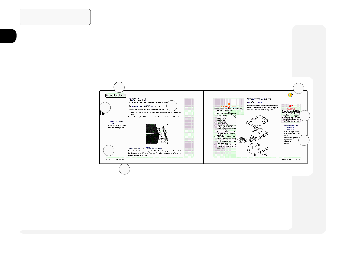
Chapter 3: Modules
Indicators............................................................................... 3-2
Swapping Modules ................................................................ 3-3
Whats Swappable? ...................................................................3-3
HDD ..................................................................................... 3-4
Removing the HDD Module .....................................................3-4
Installing the HDD Cartridge ................................................3-4
Replacing/Upgrading the Cartridge........................................... 3-5
Setting Up a New HDD for the First Time ................................3-6
Drive Bay Modules ............................................................... 3-7
Removing a Module ................................................................. 3-7
Securing a Module ....................................................................3-7
FDD (Floppy) Module ...............................................................3-8
Startup Considerations .......................................................... 3-8
Drive Bay Installation ...........................................................3-8
Parallel Connection .............................................................. 3-8
Inserting/Removing Floppy Disks ....................................... 3-10
FDD Care ........................................................................... 3-10
The Zip Module (option) ......................................................... 3-11
Startup Considerations ........................................................ 3-11
Operation ...........................................................................3-13
Chapter 4: Firmware
The Power-On Self Test (POST) ............................................. 4-2
Failing the POST .......................................................................4-3
The Setup Program ................................................................ 4-4
1
2
3
4
5
6
7
8
table of contents
xi
Page 12

1
2
3
4
5
Preface
Entering Setup ...........................................................................4-4
More on Setup ..........................................................................4-5
Date and Time (Startup Menu) .............................................4-6
Boot Display (Startup Menu)................................................. 4-6
TV Setup (Startup Menu)....................................................... 4-6
Admin Password (Startup Menu) ...........................................4-7
User Password (Startup Menu) ..............................................4-7
Diskette Drive (Disks Menu) ................................................4-8
Com Ports (Components Menu) ............................................ 4-9
Parallel Port (Components Menu) .........................................4-9
PS/2 Mouse Port (Components Menu) ...................................4-9
Power Saving ...................................................................... 4-10
Enable Power Saving (Power Menu) ................................... 4-10
Customize (Power Menu) ................................................... 4-11
Suspend Controls (Power Menu) ......................................... 4-11
Resume Timer (Power Menu) .............................................. 4-11
6
7
8
xii
Chapter 5: Power
Icons ...................................................................................... 5-2
Power Hardware ................................................................... 5-3
AC Power ..................................................................................5-3
Battery Power............................................................................ 5-4
First-Time Use & Storage ...................................................... 5-4
Battery Power .......................................................................5-6
Installing & Removing a Battery Pack ..................................5-6
Power Management .............................................................. 5-9
Hardware (Battery Status & Warnings) ...................................... 5-9
Low Battery & Suspend .........................................................5-9
table of contents
Page 13

Firmware (Setup Controls) .......................................................5-10
Suspend to Disk ..................................................................5-10
Suspend to RAM .................................................................5-12
Software (Utilities) .................................................................. 5-13
APM ................................................................................... 5-13
SystemSoft PowerProfiler .................................................... 5-14
1
2
Chapter 6: Enhancements
Memory ................................................................................. 6-2
CardWizard........................................................................... 6-4
CardWizard & Operating Systems ............................................ 6-4
CardWizard & Windows NT 4.0 ...........................................6-5
Using Card Wizard ...................................................................6-5
Power Management.............................................................. 6-6
Using Removable Storage Cards ............................................... 6-6
CardWizard Utilities............................................................. 6-6
Supported PC Cards & ZV Socket .........................................6-8
IrDA Drivers .......................................................................... 6-9
Audio Applets ...................................................................... 6-10
TouchPad ............................................................................ 6-11
Gestures ..................................................................................6-11
Customizing Gestures .........................................................6-12
Appendix A: Specifications
Appendix B: Troubleshooting
Glossary
Index
table of contents
3
4
5
6
7
8
xiii
Page 14

1
2
Preface
Advanced User Guides
Battery Tip ................................................................................................................... 1-3
Suspend Tip ................................................................................................................. 1-3
PS/2 Note ..................................................................................................................... 1-8
Printer Note ................................................................................................................. 1-8
Screen Controls ......................................................................................................... 1-11
3
4
5
6
7
8
xiv
Special Characters (Keyboard) ................................................................................... 2-2
Configuring the TouchPad .......................................................................................... 2-4
TouchPad & Serial Device ......................................................................................... 2-5
Windows 95 .......................................................................................................... 2-5
Windows NT 4.0 ................................................................................................... 2-5
CD-ROM Drivers ........................................................................................................ 2-6
Windows 95 ........................................................................................................... 2-6
Windows NT 4.0 .................................................................................................... 2-6
Windows 3.51 ........................................................................................................ 2-6
OS/2 Warp ............................................................................................................. 2-6
DOS & Windows 3.1x ........................................................................................... 2-6
More on Video Displays ............................................................................................. 2-8
Video Setup ................................................................................................................. 2-8
Windows 95 ........................................................................................................... 2-8
Windows NT 4.0 .................................................................................................... 2-9
Display Properties Control ................................................................................... 2-10
Alternative TV Output ............................................................................................... 2-11
Configuration ....................................................................................................... 2-11
Connection ........................................................................................................... 2-11
Audio Setup ...............................................................................................................2-13
Windows 95 ........................................................................................................ 2-13
Windows NT 4.0 .................................................................................................. 2-14
PC Card Setup for Windows 95 ................................................................................. 2-16
USB and Related Chipset Setup for Windows 95 ..................................................... 2-18
Stage 1 USB setup ............................................................................................... 2-18
Stage 2 Chipset setup ........................................................................................... 2-18
advanced user guides
Page 15

Drivers & Other Considerations.................................................................................. 3-1
Replacing a HDD ....................................................................................................... 3-5
Formatting the HDD ................................................................................................... 3-6
528MB or Larger HDDs & LBA Mode.................................................................. 3-6
Zip Driver & Tools Installation .................................................................................. 3-12
Windows 95 ......................................................................................................... 3-12
Windows NT 4.0 .................................................................................................. 3-13
A Word about HDDs ................................................................................................... 4-8
Suspend to Disk Setup............................................................................................... 5-10
Space ................................................................................................................... 5-10
Setting up the Partition ........................................................................................ 5-10
Additional Power Management ................................................................................ 5-13
Installing SystemSoft PowerProfiler .......................................................................... 5-14
Installing DIMMs ......................................................................................................... 6-3
Installing CardWizard ................................................................................................. 6-4
Windows 95 ........................................................................................................... 6-4
Windows NT 4.0 .................................................................................................... 6-5
Formatting in Windows NT 4.0 ................................................................................... 6-6
Installing the IrDA Drivers .......................................................................................... 6-9
AudioRack32 Setup................................................................................................... 6-10
Windows 95/Windows NT 4.0 ............................................................................ 6-10
TouchPad Driver Installation .................................................................................... 6-11
MouseWare Driver for Windows 95 & NT 4.0 ................................................... 6-11
1
2
3
4
5
6
7
List of Figures
Fig. 1 1 Sample Pages ...................................................................1-2
Fig. 1 2 Work Panel View ............................................................. 1-4
Fig. 1 3 Left Panel .........................................................................1-5
Fig. 1 4 Right Panel .......................................................................1-6
list of figures
8
xv
Page 16

1
Preface
Fig. 1 5 Rear Panel (cover closed)................................................. 1-7
Fig. 1 6 Rear Panel (cover open) ................................................... 1-7
Fig. 1 7 Bottom Panel.................................................................. 1-10
2
3
4
5
6
7
8
Fig. 2 1 Type Keys......................................................................... 2-2
Fig. 2 2 Function Keys................................................................... 2-2
Fig. 2 3 PS/2 Keyboard Port ...........................................................2-3
Fig. 2 4 The TouchPad................................................................... 2-4
Fig. 2 5 The CD-ROM ...................................................................2-6
Fig. 2 6 The LCD Controls ...........................................................2-15
Fig. 2 7 Display Properties Control.............................................. 2-10
Fig. 2 8 Display Panel TV Settings .............................................. 2-11
Fig. 2 9 Audio Subsystem Ports ................................................... 2-13
Fig. 2 10 PC Card Sockets .............................................................2-15
Fig. 2 11 Fax/Modem Port .............................................................2-19
Fig. 3 1 Drive Modules .................................................................3-2
Fig. 3 2 Drive Indicator LEDs ........................................................ 3-2
Fig. 3 3 Removing the HDD ..........................................................3-4
Fig. 3 4 Assembling the HDD Cartridge ........................................ 3-5
Fig. 3 5 Module Removal.............................................................. 3-7
Fig. 3 6 FDD Status Indicator ........................................................ 3-9
Fig. 3 7 Drive Bay with FDD ........................................................3-9
Fig. 3 8 FDD/Parallel Connection .................................................3-9
Fig. 3 9 Drive Bay with Zip (swappable with LS-120) ................. 3-11
Fig. 4 1 Sample Startup Screen: The POST ................................... 4-2
Fig. 4 2 Setup Main Menu.............................................................4-5
xvi
list of figures
Page 17

Fig. 5 1 Connecting AC Adapter ...................................................5-3
Fig. 5 2 Pull the Battery Out by the Tab ........................................5-6
Fig. 5 3 2ND Battery Pack ............................................................... 5-7
Fig. 5 4 PowerProfiler .................................................................. 5-15
Fig. 6 1 Inserting the DIMM .......................................................... 6-3
Fig. 6 2 Mouse Properties ............................................................ 6-12
List of Tables
1
2
3
4
Table 1 1 Hot Key Controls............................................ 1-11
Table 1 2 LED Indicators .......................................... 1-12,13
Table 2 1 Video Output Key Combination Sequence ... 2-12
Table 5 1 LED Power Indicators .......................................5-2
Table 6 1 Default TouchPad Gestures............................ 6-11
list of tables
5
6
7
8
xvii
Page 18

1
2
3
4
5
6
7
Preface
NOTES:
8
xviii
Page 19

1
2
¯
Advanced users should check the sidebars
which look like this.
Youll find setup information about drivers, tips
and more detailed information about the
notebooks various features.
Beginners are welcome too. As you get used
to your computer, you may be surprised at how
much of this stuff you can understand.
1 Introduction
This manual explains the hardware and essential software you need
to operate your notebook computer. Information about non-essential or enhancement software is also included, but in a separate section. Depending on how your system is configured, some
or all of the features described may already be set up.
If youre an advanced user, you may want to skip over most of this
manual. However, you should still look at the Quick Start guide
page 3 of this chapter. Also look at Chapter 5: Power. Information that
might be of partic ular interest to you is indicated by the ¯ symbol
and is found in the gray areas of each chapter.
If you are new to the wonders of notebook computers, or just feel
like a beginner, you should still look over all of the documentation.
Dont worry if you don't understand everything the first time around.
Just keep this manual near your computer, and learn as you go.
1 1
3
4
5
6
7
8
Page 20
1
Introduction
No matter what your level, please pay careful attention to warning
and safety information indicated by the M symbol. Also, pay
careful attention to the safety information in the Preface.
2
3
SAMPLE PAGES
FIG. 1 1
1. chapter topic
4
2. general/beginner text
3. chapter tab
4. page #
5
5. quick key
6. advanced user text
7. chapter icon
6
8. warning text
9. graphic key
7
8
Operating systems (i.e. Windows 95, Windows NT 4.0 , OS/2 Warp,
UNIX, etc.) have their own manuals as do application software (e.g.
1
3
4
5
word processing and database programs). If you have questions
about those programs, you should consult those manuals.
2
6
7
8
9
1 2
styles
Page 21

PACKING CONTENTS
Keep the packing materials in a safe place in case you need them
for shipping or long-term storage.
QUICK START
If you're already familiar with notebook computers, the steps listed
below tell you how to start up the notebook for the first time. They
assume that you know where all of the parts of the computer are.
You should review these steps, before you take any action. If you
arent sure about one of the procedures, check the relevant chapter
before continuing.
þ
Tip
When you get your system, the
battery(ies) may not be fully
charged. Follow the procedure
in Chapter 5: Power, First Time
Use and Storage (page 5-4), to
charge the battery.
1
2
3
4
1. Follow the safety instructions on page iv, especially the instructions on
placement.
2. Remove all packing materials, floppy disks and any PC Cards.
3. Secure the main battery pack in its compartment. (Ch. 5)
4. Securely attach any peripherals you want to use with the notebook (i.e.
mouse or keyboard) to their ports. (Ch. 1)
5. Attach the AC adapter to the port on the rear of the computer. (Ch.5)
6. Plug the AC power cord into an outlet.
7. Connect the AC power cord to the AC adapter.
8. Raise the lid/LCD to a 90o angle.
9. Push in the button (power switch) to turn on.
þ
Tip
If you plan to use the Suspend
to Disk option in the future,
setup the partition before you
partition and format your hard
disk. Refer to Chapter 5:
Power for details.
1 3quick start
5
6
7
8
Page 22
Introduction
1
2
3
4
5
6
7
8
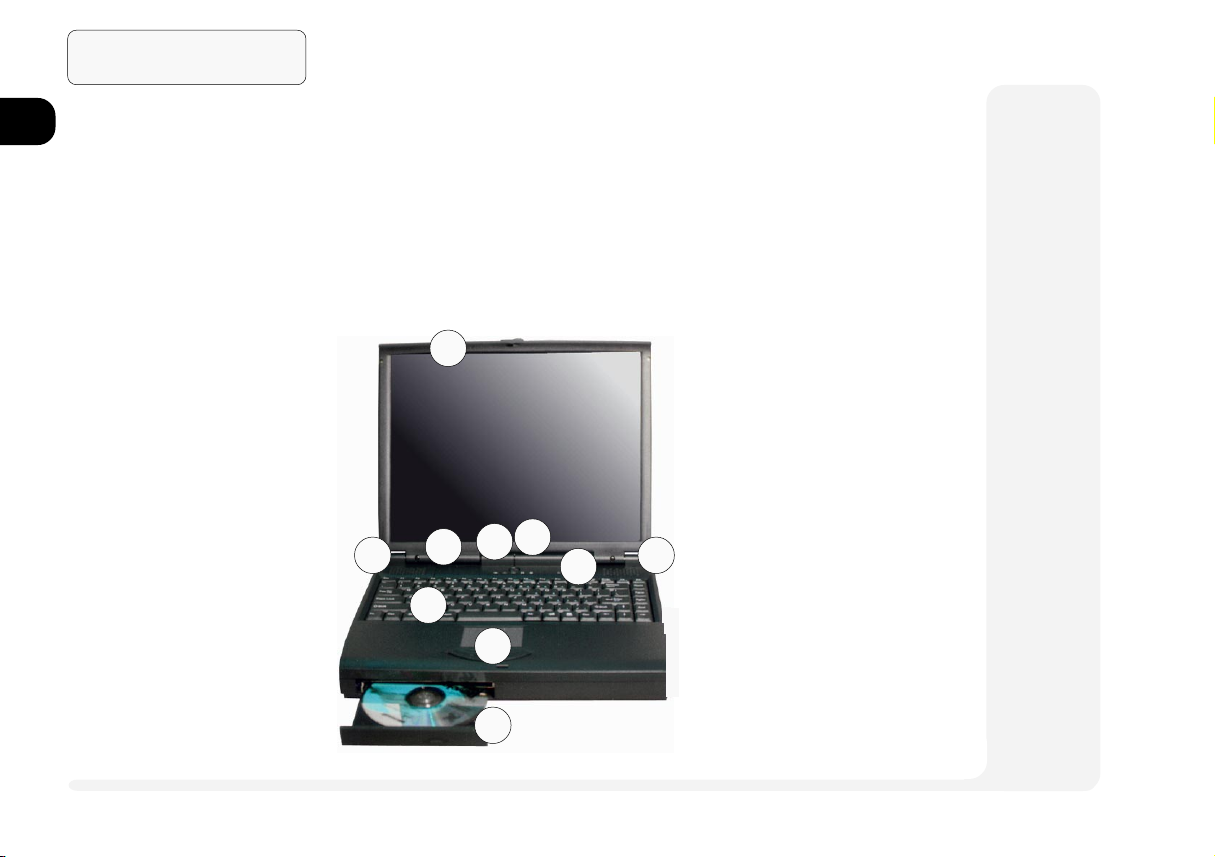
WORK PANEL VIEW
FIG. 1 2
1. microphone
2. speakers
3. close-cover switch
4. power button
5. power-on light
6. status LEDs
7. keyboard
8. TouchPad & buttons
9. CD-ROM
SYSTEM MAP
The following graphics are a general map of the notebook computer. Explanations of the various subsystems are covered in the
chapters indicated.
FRONT VIEW: WORK PANEL, LCD & CD-ROM BAY
Latch To open the notebook cover, slide this latch to the right.
TouchPad Chapter 2: System covers basic functions.
1
LCD Video functions
are covered in
Chapter 2: System.
CD-ROM Chapter 2: Sys-
tem covers basic
audio functions.
2
3
6
7
8
9
2
5
4
Chapter 6: Enhancements, has
additional audio
utilities.
1 4
front view
Page 23
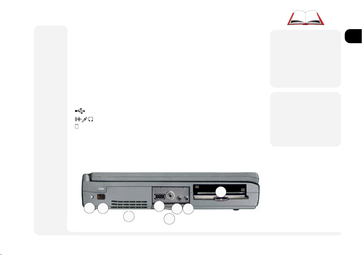
LEFT VIEW: RESET, IRDA, USB, AUDIO & PC CARD
(Reset) This is like the reset button on a desktop computer. To use it,
press in using a probe (e.g. a straightened paper-clip).
IrDA This port uses (serial) COM2 resources. The infrared connection
supports the SIR, FIR and ASK standards. Its most common use is
for a printer, modem or LAN.
Note: Newer versions of Windows 95 have an IrDA driver built-
in. For older versions, support is available from Microsoft Corp.
For other operating systems and IrDA standards, consult your
system vendor. Also consult the users guides for the device this
port is going to work with.
(USB) Refer to Chapter 2: System on how to activate this port.
(Audio) Setup for this subsystem is covered in Chapter 2: System.
(PC Card) Your computer uses newer technologies than the drivers included in Windows 95. Use the setup procedure detailed
in Chapter 2: System. Supplemental PC Card drivers are detailed in Chapter 6: Enhancements, PC Cards.
8
1
2
3
4
5
76
M
Warning
Pressing the Reset button
will cause the computer
to reboot. Any data not
saved will be lost.
M
Warning
Do not block the fan.
Overheating may cause
the system to become
unstable.
LEFT PANEL
FIG. 1 3
1. reset
2. serial 2 IrDA port
3. system cooling fan
4. USB port
5. phones - using this port
disables the speakers.
6. mic-in
7. audio line-in
8. PC Card compartment
including PC Card ZV port
1
2
3
4
5
6
7
8
left view
1 5
Page 24
1
2
3
4
5
6
Introduction
M
Warning
Dont try to remove the
hard disk (HDD) while
the system is on. This
could result in data loss
or damage.
Dont try to remove a
module in the drive bay
(i.e. FDD or Zip) while
the system is accessing
it. This may cause the
system to crash.
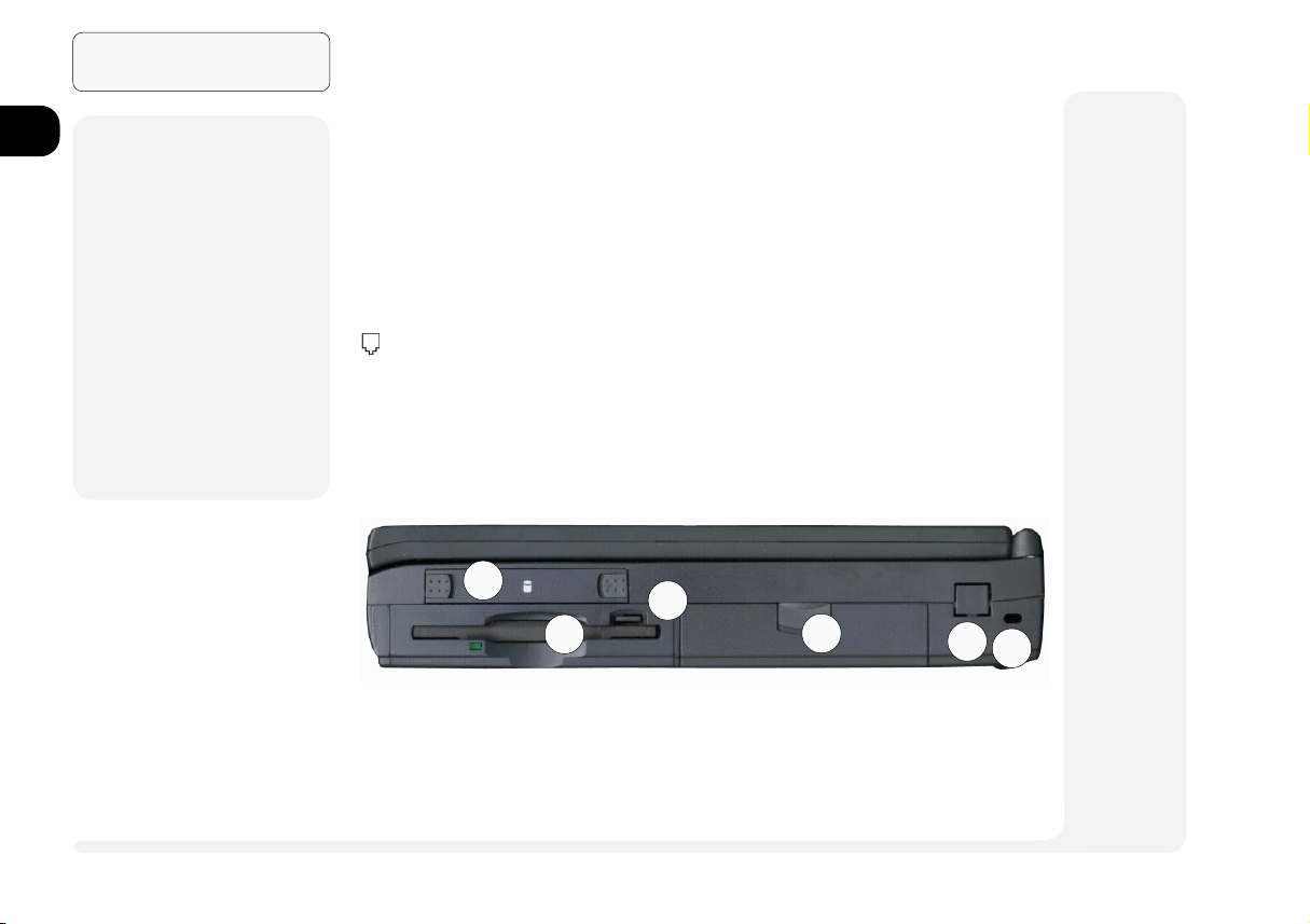
RIGHT VIEW: HDD, DRIVE BAY, POWER BAYS & FAXMODEM (OPTION)
HDD Bay Refer to Chapter 3: Modules for more on how to setup
or replace a HDD.
Drive Bay Chapter 3: Modules, covers the options available for
this bay.
Power Bay Refer to Chapter 5: Power for all aspects of the power
system.
(Fax-Modem+) Factory installed option. If your system
doesnt have a fax-modem installed, this slot will have
a cover. Do not remove it. Ask your dealer about installing a fax-modem module.
+
not immediately available
RIGHT PANEL
7
1. HDD Bay
2. Drive Bay (with FDD)
3. FDD eject button
8
4. Power Bay
5. fax-modem (option)
6. Kensington lock port
1 6
FIG. 1 4
right view
1
2
3
4
5
6
Page 25
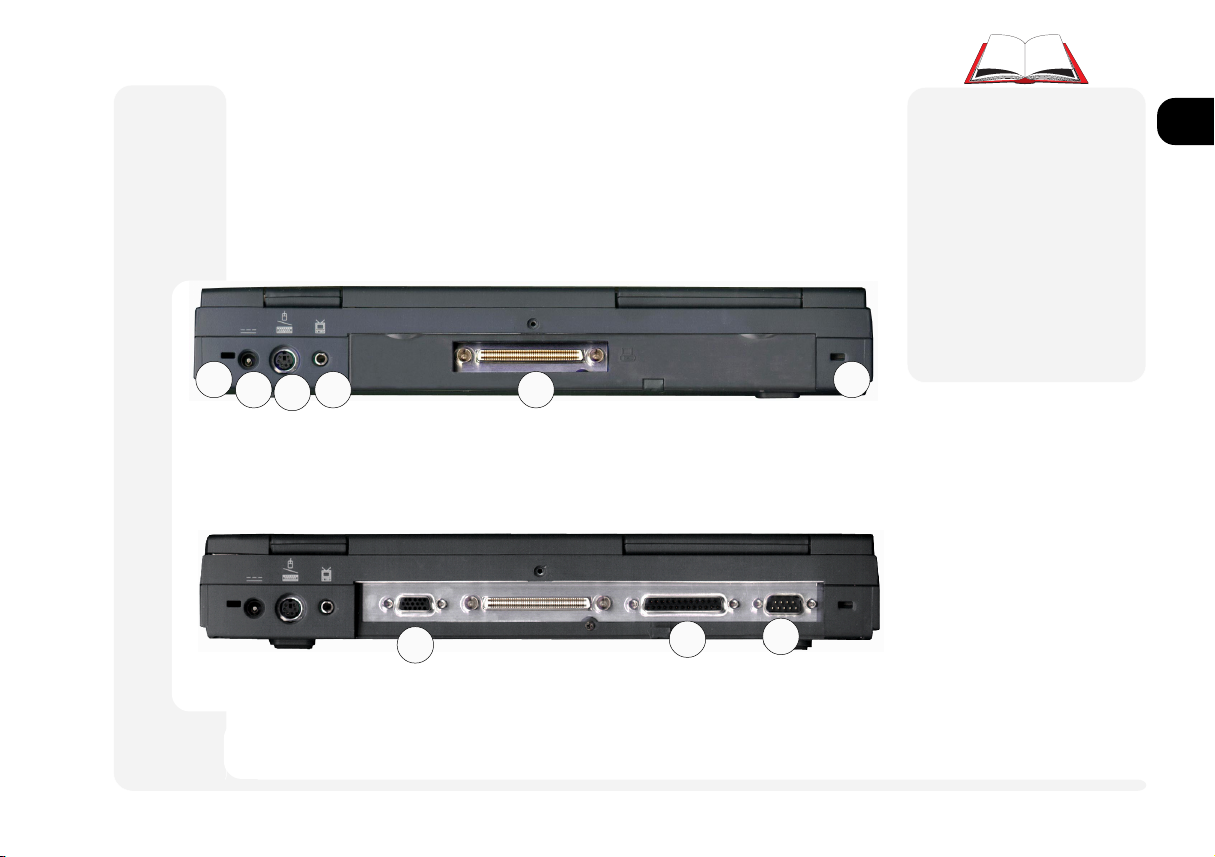
REAR VIEW:PORTS
The principal peripherals plug in on this panel. To be safe, turn off
both the system and peripherals before connecting them. Turn the
peripherals on first, before you turn on the system.
1
2
3
54
M
1
Warning
The default setting in
Setup makes all ports
hot. Depending on the
peripheral, this could
cause a problem when
you attach it. Check your
peripherals manual before you make a connec-
1
tion.
REAR PANEL (COVER CLOSED)
FIG. 1 5
1. Docking station guides
2. adapter port
3. PS/2 port
4. TV-out
5. expansion port & door
(open)
2
3
4
5
6
7
6
7
8
REAR PANEL (COVER OPEN)
FIG. 1 6
6. external monitor port
7. LPT1 parallel port
8. COM1 serial port
rear view
1 7
8
Page 26

1
2
3
4
5
6
7
8
Introduction
¯
PS/2 Note
You can only use one
type of PS/2 device per
system session. If you
want to use a different
device (mouse or keyboard), you must shut
down and restart the system. However, you can
detach and reconnect
the same device during
a system session.
¯
Printer Note
Your operating system
may include drivers for
many printer models.
Consult your printer
dealer for the most recent
driver for your model, as
this can greatly affect the
performance of the
printer.
Kensington Lock This is a standard security port.
[PS/2 Port] Use this with any standard PS/2 external
keyboard or mouse. For details, refer to Chapter 2:
System, TouchPad.
[TV-out Jack] This is explained in Chapter 2: System.
[External Monitor] Use this port with any standard
color VGA monitor. For details, refer to Chapter 2:
System.
[Expansion Port] With the main hinged door closed,
connect to this port through the sliding door. The optional docking stations manual has more information.
[Parallel Port] This port supports several standards:
Standard AT (Centronics)
Bidirectional
Enhanced (EPP) -versions 1.7 & 1.9
Extended Capabilities (ECP)
Most printers use the Standard mode. The Setups
Help bar (refer to Chapter 4: Firmware) explains how
to adjust this setting. Your peripherals manual explains
how to configure the device.
This port also serves as the external FDD connection.
Refer to Chapter 3: Modules for more on this feature.
1 8
rear view
Page 27

[COM1 (serial)] Use this with any 9-pin serial device
(e.g. a mouse, serial printer or modem). Consult the users
guides for the device this port is going to work with. For
pointing devices, refer to Chapter 2: System, TouchPad.
1
2
3
4
5
6
7
8
rear view
1 9
Page 28
1
2
3
4
5
Introduction
M
Warning
Follow the safety instructions for using
modules.
M
Warning
Do not block the fan.
Overheating may cause
the system to become
unstable.
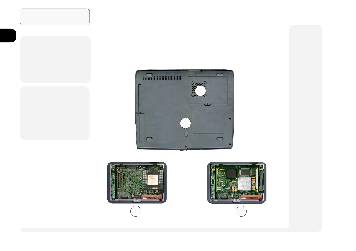
BOTTOM VIEW: COMPARTMENTS
The Drive bay is covered in Chapter 3: Modules.
There is nothing user-serviceable in the CPU compartment. Do not
open this compartment. Doing so may violate your warranty.
2
1
6
1. Drive bay expansion
7
2. CPU compartment fan
3. PPGA CPU view*
4. MMO CPU view*
8
* These views are provided to satisfy curiosity. Do not attempt to access the CPU compartment.
Doing so may violate your warranty.
BOTTOM PANEL
FIG. 1 7
module release latch
1 10
3 4
bottom view
Page 29
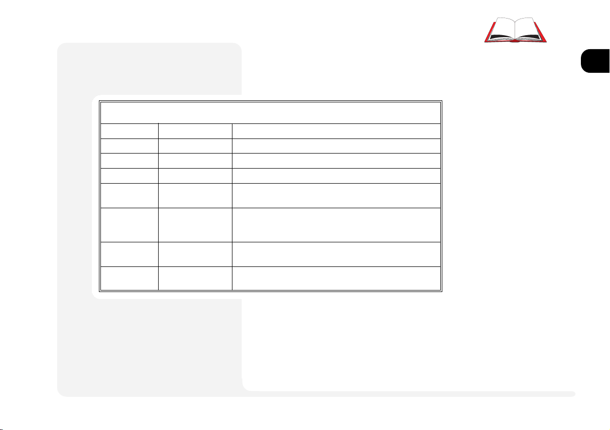
HOT KEY Controls
Some of the features are managed by
Fn+key combinations:
Keys Control Comment
Fn + F3 contrast down reduces LCD image contrast (DSTN display only)
Fn + F4 contrast up increases LCD image contrast (DSTN display only)
Fn + F5 brightness down reduces LCD brightness
Fn + F6 brightness up increases LCD brightness
Fn + F9 CRT/LCD/TV toggles between display devices: monitor, LCD, TV
and combinations. (Refer to video setup information)
Fn + F10 suspend switch activates Suspend to Disk (if that feature is enabled)
toggles between suspend function on & off (Suspend To
RAM only)
Ctrl + Alt + S enter Setup If pressed immediately after boot-up, this starts the Setup
utility
(any key) resume This ends power-saving mode including Suspend To RAM
(but not Suspend To Disk)
1
2
3
4
Table 1 1
Hot Key Controls
5
6
7
¯
Screen Controls
Active matrix TFT screens have excellent contrast ratios, so the contrast control
is not needed.
Whenever you use a key combination,
start pressing them in the order they are
listed. Dont release any of the keys in a
sequence until youve pressed the last
one.
8
1 11hot keys
Page 30
Introduction
1
2
3
4
5
6
7
8
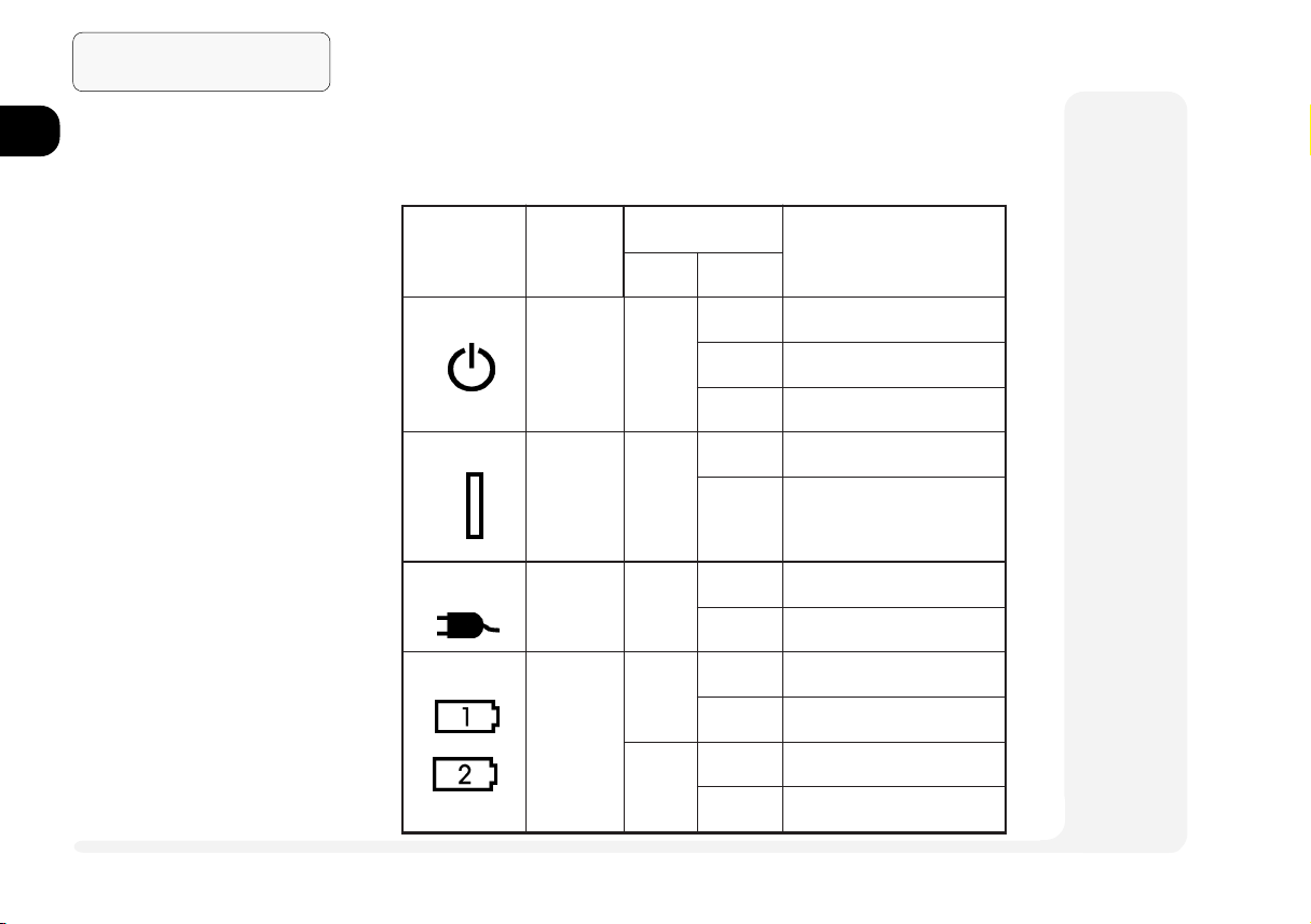
Table 1 2
LED INDICATORS
LED INDICATORS
Your notebook lets you know what its doing with the following
LED indicators.
noitairaV
rotacidnI/DELemaN
FFO/nO
hctiws
raBrewoP)setatslla(
rewop-CA)setatslla(
metsyS
etatS
ni-CA
sutatSyrettaB
yrettaB
ylno
)setatslla(
roloC
thgilonksiDotdnepsuS/FFOmetsys
NOybdnatS/ezoD/nOmetsys
gnihsalfMARotdnepsuS
NO
thgilon
NOretpadaCAmorfrewop
FFOderewopyrettab
neergdegrahcylluf
dergnigrahcsiyrettab
thgilonKOegrahcyrettab
gnihsalf
neerg
nOmetsys
woLyrettab
FFOmetsys
ksiDotdnepsuS
gninaeM
MARotdnepsuS/ybdnatS/ezoD
1 12
LEDs
Page 31

rotacidnI/DELemaNgninaeM
DDFeludomDDFgnissecca
1
2
3
DDHDDHgnissecca
kcoLmuNdetavitcadapyekciremundeddebme,degagnesikcoLmuN
kcoLspaCesacreppuerasyekcitebahplalla,degagnesikcoLspaC
kcoLllorcSdegagnesikcoLllorcS
Table 1 2 (cont.)
LED Indicators
LEDs
1 13
4
5
6
7
8
Page 32

1
2
3
4
5
6
7
Introduction
NOTES:
8
1 14
notes
Page 33

2 System
This chapter is about the first parts of the system youre likely to work with:
input output communications
keyboard video & audio PC Card
TouchPad USB
CD-ROM/DVD
Fax/Modem
1
2
3
4
5
Advanced users will also find essential driver setup information for the audio and video subsystems. More specialized driver information for the PC Card subsystem and chipset are in
Chapter 6: Enhancements.
The driver setup information described in this chapter assumes the software is located on a
CD-ROM identified as drive D:. If the driver is available from another location, please
substitute that source in the configuration.
Networking Note: Make sure youve down-loaded the driver from the network source to your
hard drive before you begin any installation. In some cases, the operating system must reboot
as part of the installation process and must have the driver immediately available.
not immediately available
2 1
6
7
8
Page 34

System
1
2
3
4
5
6
7
8
TYPE KEYS
FIG. 2 1
The embedded numeric
keypad (outlined) is activated by pressing
NumLock its LED will
light).
FUNCTION KEYS
FIG. 2 2
KEYBOARDS
Your computers keyboard has all the
functions of a full-sized AT-compatible
keyboard plus a few extras:
Type These keys are like those on a
typewriter.
Function Many applications and your op-
erating system use these keys to
access special features, so you
should consult those manuals.
Hot Keys These keys (and combinations)
control some of the hardware.
Refer to page 1-11.
¯
Special Characters
Some software applications allow the number-keys to be used in conjunction with Alt
to produce special characters. These special
characters can only be produced by using
number keys on the embedded numeric keypad. Regular number keys wont work.
2 2
keyboard
Page 35

EXTERNAL KEYBOARDS
You can attach an external keyboard to the (PS/2) port. If you
dont have a 6-pin keyboard connector, use a 5-to-6 pin adapter
cable. The system automatically detects
and enables the external keyboard as
well as the notebooks. However, for
those functions requiring the Fn key,
you will still need to use the notebooks
keyboard.
This port can only accept one type of
device configuration per system session. For example, if you connect a
PS/2 mouse to this port, you cannot
connect a keyboard to the port during
the same system session. Doing so will
cause a system conflict. If you already
have a mouse attached, and want to
use a keyboard instead, you must shut
down and restart the system. However,
you can detach and reconnect the same device during a system
session.
PS/2 KEYBOARD PORT
FIG. 2 3
1
2
3
4
5
6
7
8
2 3keyboard
Page 36

System
1
2
3
4
THE TOUCHPAD
FIG. 2 4
1. sensor pad
5
2. left mouse button
3. right mouse button
Note for left-handers: Most
6
operating systems allow you
to reverse the mouse-button
settings.
7
8
TOUCHPAD
The system automatically enables the builtin TouchPad. If youre using any version
of Windows or OS/2, you dont have to
install a driver for it.
If you want to use the TouchPads advanced features, refer to the dirver information in Chapter 6: Enhancements.
1
2
TOUCHPAD & SERIAL DEVICE
If you want to use a serial device as
well as the TouchPad, you must make
sure the devices driver can see it on
COM1. In some operating systems, you
3
¯
Configuring the TouchPad
The TouchPad uses the PS/2 port which is factory enabled. It can use the Microsoft, or IBM
PS/2 mouse driver available with most operating systems. Optimized TouchPad software for
various operating systems is in the Drivers/Utili-
ties CD-ROM which came with the system and
is covered in the Chapter 6: Enhancements.
2 4
TouchPad
Page 37

¯
TouchPad & Serial Device
Windows 9x/Windows NT 4.0
1. Attach the serial device when the system is off.
2. Turn on the system and allow the operating
system to detect and configure the device
on the serial port (COM1). Insert the
manufacturers driver disk(s) if required.
3. Both devices are enabled.
Note: If you want to take advantages of using a
Microsoft Intelli Mouse, you must first select
Intelli Mouse from the PS/2 Mouse Type of the
Components menu in the BIOS Setup (see Chap-
ter 4: Firmware).
To switch back to the TouchPad exclusively:
1. Exit the operating system (i.e. Windows 9x
family or Windows NT 4.0).
2. Detach the serial device.
3. Start the operating system. It will automatically enable the available pointing device,
in this case the TouchPad.
For information on how to change mouse settings for other operating systems, consult the
manuals for those operating systems.
can only use one pointing device driver
at a time, either serial or PS/2. To use
a serial device, first enable it by attaching it to the
system is OFF) and then start up and
configure it with a suitable driver.
port (while the
TOUCHPAD & PS/2 DEVICE
If you havent installed any specialized mouse drivers, you can also use a
mouse connected to the
Just make the connection, and the sys-
tem automatically detects an attached
mouse, enabling it as well as the
TouchPad using the same drivers.
Session Note:The PS/2 port only accepts
one type of device per system
session. If you want to switch
to an external keyboard on
this port, you must shut down
and restart the system. However, you can detach and reconnect the same device during a system session.
(PS/2) port.
1
2
3
4
5
6
7
8
2 5TouchPad
Page 38

System
1
2
3
4
5
6
7
8
FIG. 2 5
INSERTING & REMOVING ACD-ROM
To insert a CD-ROM, follow these
steps:
1. With the notebook turned on, press the
button on the front of the module to release the spring-loaded tray.
2. Gently pull the tray out to its fullest extension.
3. Insert your CD-ROM shiny-side down
(like an audio CD).
4. Gently push the tray in until it clicks in
place. The CD-ROM is ready to play.
To remove the CD-ROM, press the
same button to release the tray.
If the notebook is turned off, you can
open the tray by inserting a probe (e.g.
a straightened paperclip) into the small
hole next to the button.
THE CD-ROM
¯
CD-ROM Drivers
WINDOWS 9X
WINDOWS NT 4.0
WINDOWS NT 3.51
OS/2 WARP
These operating systems automatically detect
and configure an installed CD-ROM module.
DOS & WINDOWS 3.1X
If youre using one of these operating systems,
you must manually install the CD-ROM driver:
1. Open the 24X directory on the floppy disk,
and type:
INSTALL.EXE
2. As each page appears, press Y or Enter to
confirm the settings.
If you dont want to install the driver in the
default directory (C:\CDROM), when the
Specify the directory... dialog box appears, use Backspace to delete the current
name, then type in your preference. Remember to start the directory name with
C:\.
When you get to the Specify the parameter... page, make sure the ( )/D
[CDROM001] switch has an asterisk(*).
Then press Enter.
3. When the installation is complete, remove
the floppy disk and reboot your computer.
2 6
CD-ROM
Page 39

MULTIMEDIA APPLICATIONS
MPEG
If you want to use the CD-ROM to watch movies or other MPEG
features, there are two options:
1. Software- There are various software products which make
use of the raw power of your systems CPU to decode MPEG1
material.
1
2
3
2. ZV-PORT- The lower PC Card socket supports a ZV card. This
card works with the CD-ROM and video subsystems to produce better quality images. However, to use it, you must install these drivers:
The CD-ROM driver (covered in this chapter)
The audio and video drivers (covered in this chapter)
SystemSofts CardWizard (refer to Chapter 6:Enhancements)
VPM driver
ZV Card driver (supplied by the ZV Cards manufacturer)
AUDIO CDS
Audio CDs are played using a CD-player application included in
your operating system.
4
5
6
7
8
2 7CD-ROM
Page 40

System
1
2
3
4
5
6
7
8
THE LCD CONTROLS
FIG. 2 - 6
1. Contrast controls
(not active with TFT)
2. Brightness controls
3. Display toggle
(LCD/CRT/TV)
VIDEO
There are three display options: the
notebooks LCD, an external monitor
(CRT) and a TV. You can select between them with the Fn+F9 toggle or
the controls embedded in the video
driver interface. The interface also lets
you change the screen resolution and
color output to whatever is most comfortable/efficient for you.
As you examine the video driver (see
the side-bars for setup information), youll
notice that some displays have more flexibility than others. This is a matter of hardware, video memory and the driver for
your operating system. The driver interface shows the available options.
21
{
{
3
¯
More on Video Displays
Appendix A: Specifications has a chart of the
systems display capabilities (see page A-4).
¯
Video Setup
WINDOWS 9X
To setup the Windows 9x video driver and utilities:
1. Open Control Panel > Display.
2. Click on Settings > Advanced Properties >
Adapter or Settings > Advanced...> Adapter.
3. Click on the Change... (button). For Windows
98, you need to click on Next, and choose
Display a list of....., so you can select the driver
you want. Click on Next again.
4. Insert the Drivers/Utilities CD-ROM.
5. Select Have Disk....
Click on Browse... and navigate to:
D:\drivers\win95\video\s3vmx.inf*
or D:\drivers\win98\video\s3vmx.inf*
Click on OK and then OK again.
* This assumes your CD-ROM is drive D:.
6. Select S3 Inc. ViRAGE MX+ and click OK.
7. After the installation finishes, it will return to the
the Adapter panel.
Click on Monitor > Change...(button) and
choose a Laptop Display Panel (any size).
Click on OK and then Close (twice). When
prompted, close any other applications and
click on Yes to allow the system to restart.
2 8
video
Page 41

¯
Video Setup (cont.)
WINDOWS NT4.0
To setup the Windows NT video driver and utilities:
1. Open Control Panel > Display.
2. Click on Settings > Display Type... .
3. Click on the Change... (button) in the vga
compatible display adapter field.
4. Insert the Drivers/Utilities CD-ROM.
5. Select Have Disk....
Click on Browse... and navigate to
D:\drivers\nt40\video\S3virge.inf*
Click on Open and then on OK (twice).
* This assumes the video driver is on a CD-ROM identified
as drive D:.
6. Select S3 Incorporated Display Driver...
and click on OK or Yes to start the installation.
7. After the installation finishes, Windows NT
4.0 will tell you to close the various screens
and reboot. When you restart and return to
the Display page, you can change the settings. When finished, you must Apply the
new settings to take effect.
This driver doesnt support different image output.
SETUP
The video drivers on the accompanying
Drivers/Utilities CD_ROM are optimized
for specific operating systems. If the
driver for your operating system isnt
available, or you suspect its outdated,
consult your dealer. These drivers are
required if you want to use a TV display
or want enhanced performance on an
external monitor as well as the LCD.
The instructions in the side-bars tell you
how to install the drivers. However, your
operating systems documentation may
have additional tips.
Note: For most operating systems, video
driver installation is different from
any other drivers (e.g. sound).
LCD
AS you open the lid, adjust it so you can
look at the screen straight-on, without
any glare. If necessary, adjust the brightness and contrast controls.
M
Warning
Do not allow any foreign
objects (i.e. paper or
plastic) to get between
the lid/LCD and the work
panel. They could damage or scratch the LCD
and/or accidentally activate the close-cover
switch.
1
2
3
4
5
6
7
8
Note: If your model has a TFT screen, the
contrast controls arent necessary.
2 9video
Page 42

1
2
3
4
5
6
7
8
System
M
Warning
Both the monitor & computer should be OFF before you connect them.
DISPLAY PROPERTIES C ONTROL
FIG. 2 - 7
The driver for your operating system may not
need additional controls.
If it does, use this control
panel to adjust screen refresh rates and TV output.
ATTACHING A MONITOR
If you prefer to use an external monitor, connect it to the VGA port on the
rear panel.
Note: The vertical refresh rate of your
monitor is very important. If its too
low and/or youre using fluorescent
lighting, the screen will appear to
flicker. To reduce flickering on an
external monitor, use faster refresh
rates (we recommend a refresh
rate of 72Hz or more). But first
check your monitors
documentation to make
sure it can support the
rates listed by the video
driver. The default refresh rate for VGA monitors (without drivers) is
60Hz. For NTSC and
PAL TVs, its fixed at
60Hz and 50Hz, respectively.
¯
Video Setup (cont.)
The S3 driver adds an additional page to Display
Properties. This has current display status infor-
mation. It allows you to select the control system, output devices and image processing:
Single control devotes all video memory to a
single display system (the LCD/CRT choice
will display exactly the same thing)
Dual control divides the video memory to sup-
port 2 devices. It also lets you select the
type of external monitor you are using.
Use the on-line help (?) to get more information
about the various features.
2 10
video
Page 43

¯
Alternative TV Output
CONFIGURATION
By default, your computer is configured for S
type video output. If your configuration requires
the earlier, AV output, be sure to change the
TV-Output Signal to Composit.
CONNECTION
If the Y-cable cant reach the S or Composit
port on your TV, you should be able to get an
extentsion from your local Audio-visual dealer.
TV SETUP IN SYSTEM C ONFIGURATION
If you want to use Fn + F9 to
switch to the TV display, you
must enable the TV function in
the BIOS:
1. Boot the system, then imme-
diately press Ctrl+ Alt + S to
start the Setup utility.
2. Select Startup, then TV
Setup.
3. Click on Enable TV option.
Then choose the settings for
your TV and connector
types. Then Click OK.
4. Select Exit, choose the Save
and Exit option.
TV
To use a TV display instead of the LCD
and/or monitor, connect the Y-cable
TV-adapters mini-din plug to the TVout port. This cable allows you to use
either an S type or Composit connection to your TV.
But, before you use this connector,
make sure you have enabled the TV
feature in the systems Setup (see
sidebar for details) and the driver is
configured for your
TVs standard: NTSC or
PAL (use the video
driver control panel).
Note: The default refresh
rate for NTSC and PAL TVs
is fixed at 60Hz and 50Hz,
respectively. And to enable
TVs speakers, you must
use a cable between the
computers headphones
port and your TVs audioin port.
M
Warning
Both the TV & computer
should be OFF before
you connect them.
M
Warning
The NTSC and PAL settings can only be used
with the appropriate
televisions.
DISPLAY PANEL TV SETTINGS
FIG. 2 8
Be sure the NTSC/PAL
setting on the TV page
is correct.
1
2
3
4
5
6
7
8
video
2 11
Page 44

1
System
SWITCHING
You can switch to the TV display using the video driver control
panel or by toggling Fn + F9. The toggle sequence is:
2
3
4
5
6
7
8
TABLE 2 1
VIDEO OUTPUT
KEY COMBINATION SEQUENCE
VT
dradnatS
*CSTN
LAP
*CSTN
LAP
*
Since NTSC resolution (640 x 400) is narrower, TV view compensates with the
panning effect. And, to make the toggle sequence work, you must enable TV
feature in the systems Setup (see page 2-11 for details).
DCL
noituloseR
084x046
006x008
084x046
006x008
084x046
006x008
084x046
006x008
>rotinomVTDCL>
>rotinomVT+DCL>VT
DCL>
ecneuqeSelggoTtnemmoC
)syalpsidllanoegamiemas(lortnoCelgniS
>rotinom+DCL>DCL
)syalpsidllanoegamitnereffidroemas(lortnoClauD
>rotinom+DCL>DCL
siVTCSTNrofnoituloserehT
DCLeht,revewoh;004x046
)084x046(AGVsatistaert
nahtregralsnoituloserllA
htiwdeweiveraCSTN
VTnotceffegninnapeht
AGVhtobstroppusLAP
snoituloserAGVSdna
siVTCSTNrofnoituloserehT
DCLeht,revewoh;004x046
)084x046(AGVsatistaert
nahtregralsnoituloserllA
htiwdeweiveraCSTN
VTnotceffegninnapeht
AGVhtobstroppusLAP
snoituloserAGVSdna
2 12
video
Page 45

¯
Audio Setup
WINDOWS 95
Your Windows 95 Setup utility cannot detect
the latest version of the ESS AudioDrive utility.
The utility included with your notebook takes
advantage of technical improvements since
Windows 95s release. To install,
1. Open Control Panel > System > Device
Manager.
2. Click on Other devices, and remove all
devices named as Unknown device.
3. Click on Sound, video and game control-
lers, and remove all devices except
Gameport Joystick.
4. Click on Refresh. When the Update Device
Driver Wizard appears, click on Next > Other
Locations... > Browse..., and navigate to:
D:\drivers\win95\audio*.
* This assumes your CD-ROM is drive D:
Click OK (twice), then Finish to start the installation. (Follow the programs dialog
boxes. When asked for Driver Disk, insert the Drivers/Utilities CD-ROM, then click
on OK then on Browse... and navigate to
D:\drivers\win95\audio.)
Click OK (twice) to allow the wizard to install
ESS 1879 Control Interface and ESS 1879
Plug and Play AudioDrive automatically.
5. When finished, close the System Properties panel.
6. Restart your system.
AUDIO
The audio subsystem, in combination
with the CD-ROM (or DVD), gives the
computer multimedia capabilities. To
use it, You first have to install the correct drivers. These are included in the
software package which comes with
the system. The procedure is explained in the side-bars.
The ports are on the left panel:
2
1
Note: If you are using a TV display, you
must use a cable between the
computers headphones port and
your TVs audio-in port.
3
M
Warning
To protect your hearing, turn down the volume before you plug-
in either headphones
or speakers.
AUDIO SUBSYSTEM PORTS
FIG. 2 9
1. headphones
/external speakers
(disables on-board speakers)
2. microphone
(disables internal microphone)
3. line-in
Volume control is provided by toggling Fn+F7
and Fn+F8 to toggle the
volume down or up respectively.
1
2
3
4
5
6
7
8
audio
2 13
Page 46

System
1
2
3
4
5
6
7
8
ADDITIONAL AUDIO
The Drivers/Utilities CD-ROM which
accompanies your system also includes supplemental audio software
for Windows 95 and Windows NT 4.0.
Refer to Chapter 6: Enhancements
for more details.
¯
Audio Setup (cont.)
WINDOWS 98
Your Windows 98 Setup utility will detect and install
the latest version of the ESS AudioDrive utility. However
its built-in audio drivers do not support the Zoomed
Video Mixer (e.g. MEPGII, ZV card, etc.), and makes the
recorders volume become too low. If you want to use
those devices, we recommend you to install the drivers
included on the accompying CD-ROM. To install,
1. Open Control Panel > System > Device
Manager.
2. Click on Sound, video and game control-
lers, and choose ES1879 Control Interface.
3. Click on Properties > Driver > Update
Driver...(button) then Next, and choose
Display a list of....., so you can select the driver
you want. Click on Next again.
4. Insert the Drivers/Utilities CD-ROM.
5. Select Have Disk....
Click on Browse... and navigate to
D:\drivers\win98\audio\0emsetup.inf*
Click on OK (3 requests) then Yes.
* This assumes your CD-ROM is drive D:.
6. Click on Next to copy the drivers. After the
installation finishes, click on Finish to return to
the Driver panel. Click on Close.
7. Repeat steps 2 to 6. When prompted, choose
ES1879 Plug and Play AudioDrive (the older
version). When asked for Driver Disk, repeat step 5 again to complete the installation.
8. Restart your system.
2 14
audio
Page 47

¯
Audio Setup (cont.)
WINDOWS NT4.0
To install the audio driver after youre into the
system, isnert the Drivers/Utilities CD-ROM. Then,
1. Open Control Panel >Multimedia >Devices
(tab) and click on the Add button.
2. Choose Unlisted or Updated Driver from
the list. Then click Browse... and navigate
to: D:\drivers\nt40\audio*.
* This assumes your CD-ROM is drive D:.
3. Click on OK when ESS 1879 AudioDrive
appears. Choose Continue or OK to confirm the resource settings. Then restart the
system to activate the driver.
4. Once the system has restarted, double-click
on the speaker icon in the tray on the lower
right to open the sound control panel.
PC CARDS
The notebook has two PC Card expansion sockets:
socket 0 (lower), is Type III
socket 1 (upper), is Type II
Both sockets are backward -compatible.
For example, a Type III socket can
handle a Type I, II, or III card.
Both support PCMCIA (rev. 2) and
CardBus (PCI bus to PCMCIA socket).
The lower socket is Zoomed Video (ZV).
The ZV Port is a direct connection between the PC Card and the notebooks
video and audio subsystems. As such, it
works directly with the CD-ROM module to support multimedia features.
Refer to the documentation which comes
with your ZV card for more information
about its capabilities and how to use its
features.
2
1
PC CARD SOCKETS
FIG. 2 10
1. socket 0 (lower)
eject button
2. socket 1 (upper)
eject button
1
2
3
4
5
6
7
8
PC Card
2 15
Page 48

System
1
2
3
4
5
6
7
8
OPERATING SYSTEMS
WINDOWS 95
The PC Card components are newer
than the drivers supplied by Windows
95, so before you can use this device,
you must make some changes (described in the side-bar) to your system. However after you activate them,
they are always hot.
The updated drivers are also PCMCIA
(rev. 2) , and CardBus compliant and they
recognize Plug n Play PC Cards. However some older, legacy, cards may require their own drivers. You can hot swap
any PC Card (refer to Chapter 3: Modules
for a discussion on swapping). If you want
to use a ZV card, install the optional
SystemSoft CardWorks driver (see
Chapter 6: Enhancements).
The optional SystemSoft drivers which
come with your computer take advantage of technical improvements since
the release of Windows 95 and support legacy and ZV cards.
¯
PC Card Setup for Windows 95
The PC Card components are newer than the
drivers supplied by Windows 95, so before you
can use this device, you must make some
changes to your system:
1. Open Control Panel > System > Device
Manager > Other devices. Remove the PCI
CardBus Bridge listings (there are 2).
2. Under PCMCIA socket, remove PCIC or
Compatible PCMCIA controller.
3. Download TI-1250 driver from the Microsoft
web site or talk to your dealer. Copy the
files described in steps 4 & 5 to your system.
4. Copy PCMCIA.INF to Windows\Inf\ (replacing the existing file).
5. Copy CBSS.VXD, PCCARD.VXD and
PCI.VXD to Windows\System\ (the last two
replace existing files).
6. Return to Control Panel > System Properties
> Device Manager, and click on Refresh.
When it asks about keeping an exiting file,
say Yes (4 requests)
7. When return to Device Manager panel, Choose
Texas Intrusments PCI-1250 CardBus Controller (there are 2) under PCMCIA socket. Click
on Properties... and uncheck Disable in this
hardware profile. Follow the programs dialog
boxes to complete the settings.
After uncheck both controllers, reboot the system. Till then the sockets will be ready for use.
2 16
PC Card
Page 49

WINDOWS 98
The operating system supports the lastest PC Card drivers. It
automatcially detects and installs the required drivers for your
notebooks PC Card socket. The drivers are PCMICIA (rev. 2) compliant. You can also install or remove the card while the system is turned
on. If you want to use a ZV card, refer to the side-bar about Audio
Setup on page 2-14 for further references.
WINDOWS NT 4.0
The operating system automatically installs the PC Card socket
drivers. This driver is only PCMCIA (rev. 2) compliant. You can
install or remove cards only when the system is turned off. In particular, any I/O PC Card (e.g. LAN or SCSI) must be present when
you boot-up the system. CardBus and ZV support are not available.
The optional SystemSoft Driver allows hot insertion and hot removal,
and provides CardBus support (see Chapter 6: Enhancements).
INSERTING A PC CARD
PC Cards require drivers specific to your operating system: one for the
computers sockets (see above), and a driver for the card youre
installing. The first time you install a PC Card, Windows 95, Windows
98 and NT 4.0 prompt you for that cards driver. If your operating
system supports Plug n Play (e.g. Windows 95 & Windows 98), PC
Cards can be inserted and removed while the system is on.
M
Warning
Do not add, remove or
change cards while the
system is in a power saving mode. This may cause
a conflict with the stored
system configuration information.
M
Warning
Some operating systems
may experience difficulties if an I/O card (e.g. a
fax/modem) is present in
the socket when you
warm boot the computer.
Depending on your operating system, the COM
ports (I/O) for PC Card devices are reassigned.
Some operating systems
(e.g. Windows 95 & Win-
dows 98) do not have this
limitation.
1
2
3
4
5
6
7
8
PC Card
2 17
Page 50

1
2
3
4
5
6
System
When the card is in correctly, the system beeps once. If the PC Card is not
detected, check if the correct drivers
are loaded.
REMOVING A PC CARD
Push the appropriate eject button to
remove the card. The system will beep
twice when the card is ejected.
USB DEVICES
Like the PC Cards, your computers USB
system uses technologies which are
newer than Windows 95. These require
some modifications to your system described in the side-bar.
¯
USB and Related Chipset
Setup for Windows 95
Enabling the USB features is a two-stage process which must be followed in order:
STAGE 1 USB SETUP:
Run the Usbsupp.exe utility from Microsoft.
This may be included on the CD-ROM containing Windows 95. When the system re-
starts, continue to Stage 2.
STAGE 2 CHIPSET SETUP
Run the Intel 82371xb INF update Installer
ver1.0 . When this is installed, the system
will go through a re-detection process,
which may require several restarts of the
system (just follow the on-screen instructions).
7
8
2 18
Once your system is setup, you should
refer to the USB devices manuals on
how to operate them.
USB setup
Page 51

¯
Setting up the Fax/Modem
WINDOWS 9X
To setup the fax/modem drivers for Windows 9x
family,
1. Open Control Panel > System > Device
Manager.
2. Click on Other devices, and remove LT Win
Modem.
3. Click on Refresh. When Add New Hardware
Wizard appears, insert the Drivers/Utilities
CD-ROM, and click on Next .
(If Windows 98, you need to choose Search
for the best driver for your devive, then Next.)
4. Click on Other Locations... (if Windows 95),
Choose Specify a location (If Windows 98),
and navigate to:
d:\drivers\options\modem\win95&98&nt4
5. Follow the programs dialog boxes. When
asked for LT Installation Disk and/or Add
New Hardware Wizard reappeared, redirect to the same location as specified in step 4.
6. When the installation finishes, click Modems
icon in the Control Panel to continue the
setup (the modem should be assigned to
COM3).
Note: For Dial-up Internet access, you must be
sure to have all the proper protocols installed
(e.g. TCP/IP). Refer to your operating system
manual for this and/or your Internet Service
Providers documentation.
FAX/MODEM (OPTIONAL MODULE)
If your system includes the fax/modem module, both Windows 9x and
Windows NT 4.0 will detect it during
setup. However, our module takes advantage of newer technologies so you
will have to install our updated drives
to take advantage of its full speed.
ñ
FAX/MODEM PORT
FIG. 2 11
1
2
3
4
5
6
7
8
Fax/Modem
2 19
Page 52

System
1
2
3
4
5
6
7
8
USAGE
Once your fax/modem is setup, you
still have to configure the software that
will use it. For the most part, this means
working with your operating systems
Network settings.
Be sure to keep the original installation software handy as you do this.
Additional information about how to use
the fax/modem (e.g. ATdfcom.pdf file
for AT commands) is included with the
accompanying Drivers/Utilities CD-ROM.
¯
Setting up the Fax/Modem (cont.)
WINDOWS NT 4.0
1. Diable COM2 I/O Settings in the BIOS Setup
(see Chapter 4: Firmware).
2. Install Windows NT4.0 Service Pack 3 (SP3).
3. Navigate to i386 sub-folder on the SP3 CDROM. Highlight PnPISA.inf, then click right
mouse button and choose Install. When
prompted, close any other applications and allow to restart.
4. After system resumes, the Add New Hardware
Wizard appears. Insert the Drivers/Utilities CDROM. Click on OK > Browse and navigate to:
D:\drivers\options\modem\win95&98&nt4\Ltmodem.inf
5. Follow the programs dialog boxes to copy
the files. When prompted, choose LT Win
Modem from Model list.
6. When Resource panel appears, click on Set
Configuration Manually. Choose any
unconflicting device, such as Basic configuration 0001, from the Setting Based on
option (there are 10). When the installation
is complete, reboot the system.
7. When the computer restarts, click Modems
icon in the Control Panel to continue the
setup(the modem should be assigned to
COM2).
2 20
Fax/Modem
Page 53

3 Modules
1
2
3
4
5
¯
Drivers & Other Considerations
If your dealer hasnt done so, you must set up
both HDD and Zip drives before they can be
used for the first time. Please refer to the sidebar tips for instructions on how to do this.
The setup information in this chapter is for Win-
dows 95 and Windows NT 4.0 (workstation).
Setup information for other operating systems
may be found on the Drivers/Utilities CD-ROM,
in the relevant Readme files.
This chapter is about how to use and install these data modules:
HDD Bay Drive Bay Power Bay
HDD FDD (see Chapter 5: Power)
Zip/LS-120
If youre not sure where these modules are located, refer to Chapter 1: Introduction.
Each of these modules interacts with the system differently and so
requires different setups.
3 1
6
7
8
Page 54

Modules
1
2
3
4
5
6
DRIVE MODULES
FIG. 3 1
1. CD-ROM (see Chapter 2: System)
2. HDD
3. FDD module
4. Zip module
5. Zip disk
7
8
DRIVE INDICATOR LEDS
FIG. 3 2
6. HDD
7. Floppy bay
INDICATORS
Whenever a data module is in use, the corresponding indicator
lights up:
accessing the main HDD.
accessing the FDD.
3
2
1
6
4
5
3 2
7
indicators
Page 55

SWAPPING MODULES
Hot Swappable modules can be removed, reinstalled or replaced
with other modules without turning off the system.
Hot Removable modules may be removed but not reinstalled
while the system is turned on.
Cold Swappable modules can be removed or replaced only
when the system is turned off.
In any case, please keep the following rules in mind:
Before using a module, make sure it is secured in its bay. If a module
isnt connected properly, it could fail and/or damage data.
Though it may be convenient, hot swapping is not recommended.
If possible, turn the system off before making any swaps.
Hot-swapping a module risks accidentally crashing the machine
(and losing unsaved data), or damaging a module if its in use.
If you must swap devices, be sure to save your data first and care-
fully review the section on the module(s) in this chapter.
WHATS SWAPPABLE?
Drive bay: The FDD, Zip* and LS-120* are hot removable (but not
recommended). A battery is hot swappable with another
battery.
*refer to the Zip/LS-120 section on page 3-11.
Parallel Port: FDD+cable is hot swappable with a parallel device.
Power bay: A battery is hot swappable with another battery (while the
system is powered by an AC adapter).
HDD bay: The main HDD is cold swappable with another HDD.
1
2
3
4
5
6
7
8
3 3swapping
Page 56

Modules
1
2
3
4
REMOVING THE HDD
FIG. 3 3
1. slide the HDD latches
5
towards each other
2. pull the cartridge out
6
7
8
HDD
The main HDD is in a removable plastic cartridge.
REMOVING THE HDD MODULE
If for some reason you must remove the HDD cartridge:
1. Make sure the computer is turned off and slide the HDD latches towards each other. The HDD bay handle will pop out.
2. Gently grasp the HDD cartridge handle and pull it out.
Picture of HDD removal from notebook
ñ
INSTALLING THE HDD CARTRIDGE
To install the (new or upgraded) HDD cartridge, carefully slide it
back into the HDD bay. Push the HDD cartridge handle in and
slide the latches away from each other into their locked position.
ñ
3 4
main HDD
Page 57

¯
Replacing a HDD
You can replace your HDD with another 2.5,
12mm high IDE hard disk drive.
To assemble the cartridge,
1. Make sure the HDDs jumper pins are set
to master or device 0. Most drives
dont require any settings, but check your
HDDs documentation to be sure.
2. Holding the HDD (1) at an angle (electronic side up), plug its pins into the connector (2). Make sure all the pins are inserted fully.
3. Cover the HDDs electronic component
side with the mylar shield.
4. Insert the HDD and shield combination
into the frame (electronic side up). As you
do so, carefully fit the edges of the shield
around the screw holes of the frame.
5. Secure the HDD, shield and frame with
the four mounting screws (3)-(6).
REPLACING/UPGRADING
THE
CARTRIDGE
If youre too harried or a bit of a
technophobe, contact your dealer to purchase or replace your current HDD with
an upgrade.
1
ñ
2
3
4
5
M
Warning
Depending on the HDD,
the cartridge jumper
must be set to master
or the system will not
recognize it. Check your
drives documentation.
ASSEMBLING THE HDD
CARTRIDGE
FIG. 3 4
1
2
3
4
5
6
7
8
6
main HDD
3 5
Page 58

Modules
1
2
3
4
5
6
7
8
SETTING UP A NEW HDD
FOR THE FIRST TIME
Before you can use a new HDD for
the first time, two things are required:
The computer detects the HDD.
(this is automatic at boot-up)
Prepare the HDD to accept data.
(refer to your operating system manual)
¯
Formatting the HDD
A hard disk must be partitioned, and formatted
before use. To partition the HDD, use the utility
from your operating system (e.g. MS-DOSs fdisk
command) to do this. To format, use the utility
from your operating system (e.g. MS-DOSs for-
mat or format/s command). Consult your oper-
ating systems manual for more information on
its partitioning and formatting utilities.
If you plan to use the Suspend to Disk feature,
refer to Chapter 5: Power.
After you replace or upgrade the HDD, turn the
system on. The computer will automatically detect it.
528MB OR LARGER HDDS & LBA MODE
The computer automatically reads any HDD
528MB or larger as using LBA Mode. We do
not recommend using an HDD larger than
528MB from an older system which does not
use LBA mode. Doing so may result in problems
reading some portions of the HDD.
3 6
main HDD
Page 59

DRIVE BAY MODULES
You can plug one of three modules into this bay: the FDD, a Zip
drive, or a 2nd battery. Refer to page 3-3 for the rules on swapping.
The battery module installation is covered in Chapter 5: Power.
REMOVING A MODULE
Even though the module may be hot swappable, we recommend
making any changes with the system turned OFF.
To release a module:
1. Slide the locking latch
on the bottom part of the
module to the unlock
position and hold it.
2. Grasp the edge of the
module and pull it out of
the Drive bay and release
the latch.
2
ñ
1
ñ
MODULE REMOVAL
FIG. 3 5
1. slide locking latch
2. pull on module edge
1
2
3
4
5
6
7
SECURING A MODULE
To secure a module in the Drive bay:
1. Push the module in until its outer edge is flush with the side of the
computer.
2. The locking latch will snap into place.
8
3 7drive bay modules
Page 60

1
Modules
FDD (FLOPPY) MODULE
As mentioned on page 3 of this chapter, the FDD is hot-swappable.
It can work equally well in either the internal or external position.
2
3
4
5
6
7
8
M
Warning
Do not remove the FDD
module from the parallel
port or Drive bay while it
is active. Disconnecting
during data access may
damage the system, the
FDD or result in data loss
and/or corruption.
STARTUP CONSIDERATIONS
The FDD does not have to be present when you boot-up. If it
isnt in the Drive bay or attached to the parallel port, the POST
(refer to Chapter 4: Firmware), will tell you. This does not affect
performance: you can insert the FDD into the Drive bay or connect it to the parallel port at any time.
DRIVE BAY INSTALLATION
If the FDD is not already installed, make sure the bay is empty,
then push the FDD module in until its outer edge is flush with
the side of the computer. You should hear a click from the
locking latch on the bottom panel when the module is in place.
PARALLEL CONNECTION
If the Drive bay is occupied (e.g. with a battery), you can connect it to the parallel port with a cable (not provided). To make
the connection, attach the FDD to the cable first and then attach
the other end of the cable to the parallel port.
If you need to use the parallel port for some other purpose (e.g.
to print), you can disconnect the parallel adapter and plug in
your parallel device without turning off the system.
3 8
FDD
Page 61

FDD STATUS INDICATOR
FIG. 3 6
1. LED lights for FDD access
1
from either position
DRIVE BAY WITH FDD
FIG. 3 7
2. Floppy disk eject button
1
2
3
M
Warning
The FDD/parallel adapter
2
5
cable can only be used
with the FDD module. It
cannot be used with any
other module.
If its connected to the
parallel port, the cable
must also be connected
to the FDD module or
the system may halt.
4
5
6
7
FDD PARALLEL CONNECTION
FIG. 3 8
3
4
3. FDD module
4. FDD to Parallel adapter
5. Parallel port
FDD
3 9
8
Page 62

1
2
3
4
5
6
7
Modules
INSERTING/REMOVING FLOPPY DISKS
Gently insert a 3.5-inch disk (with its label side up) into the
Floppy drive until the disk is properly seated. Press the button
on the right of the Floppy drive to eject the disk.
FDD Care
Following are a few tips on the proper handling of floppies:
Store disks away from magnetic fields and extreme temperatures. These
conditions can damage your data. Its also a good idea to make backup
copies of software and data.
If a disk label is already on the disk, use a soft-tipped pen to write on
the label. This prevents damage to the disk. Dont use a pencil - its
carbon particles can rub off inside the drive.
Do not remove any disk from the drive when the LED is flashing (in-use).
Do not try to clean, bend, or throw disks.
Do not touch or scratch any exposed portion of the disk medium. Dont
pull open the protective door either - this lets dust get inside.
8
3 10
FDD
Page 63

THE ZIP/LS-120 MODULE (OPTION)
As mentioned on page 3 of this chapter, the Zip or LS-120 is hotremovable. However, there are some limitations (see Opera-
tion, page 3-13~14).
STARTUP CONSIDERATIONS
When you install the Zip or LS-120 drive, make sure the bay is
empty, then push the module in until its outer edge is flush with
the side of the computer. You should hear a click from the
locking latch on the bottom panel when the module is in place.
The Zip or LS-120 module must be installed before you boot-up.
If it isnt in the Drive bay when the system boots, the system
wont recognize it and wont allocate system resources.
Note: The Zip drive is not a boot device whereas LS-120 drive can
become bootable only if you activate its booting function in the
BIOS Setup.
M
Warning
Do not remove the Zip/
LS-120 module from the
Drive bay while it is active. Disconnecting during data access may crash
and/or damage the system, the Zip/LS-120 or result in data loss and/or
corruption.
1
2
3
4
5
6
ZIP
DRIVE BAY WITH ZIP
FIG. 3 9
1. emergency eject
2. accessing LED (green)
Note: Swappable with
ñ
1
ñ
2
2
LS-120
1
LS-120
Zip/LS-120
3 11
7
8
Page 64

1
2
3
4
5
6
7
8
Modules
DRIVERS & UTILITIES
The Zip or LS-120 module must be in
the Drive bay before you can install
the their respective tool suite. Although
theWindows 9x andWindows NT4.0 allocate the resource automatcially, you
still need the tools provided with the
accompanying Drivers/Utilities CD-ROM
for many of the necessary controls.
When the Zip or LS-120 installation is
complete, the Zip/LS-120 drive pushes
the CD-ROM back one letter (i.e. if the
CD-ROM is drive D:, it will become
drive E:, and the Zip/LS-120 will be
the new D:). If the Zip or LS-120 is
not present at the next boot-up, the CDROM reverts to its original letter.
To prevent confusion, follow the instructions in the side-bar on page U-10
to fix the CD-ROM to one letter.
¯
Zip Tools Installation
WINDOWS 9X /WINDOWS NT 4.0
Make sure the Zip drive is installed before you turn
on the computer.
When the operating system starts up, it automatically detects, and assigns the Zip drive to the letter
after the hard disk drive(s), pushing the CD-ROM
back one letter. The default driver recognizes the
Zip as a Removable Disk but it lacks many necessary utilities provided by Zip tools. To install,
1. Insert the Drivers/Utilities CD-ROM.
2. From the Start button (on the tool bar), select
Run.... Click on Browse... and navigate to:
E:\drivers\options\zip\English\setup*
*This assumes your CD-ROM is drive E: and your operating system is English version.
3. Click Open, and follow the programs dialog
boxes to install the tools (default installation is
recommended).
4. When the installation is complete, the computer will ask to reboot. Do so.
5. When the computer restarts, Iomega Tools will
be added to the Start menu.
3 12
Zip/LS-120
Page 65

¯
LS-120 Tools Installation
WINDOWS 9X /WINDOWS NT 4.0
Make sure the LS-120 drive is installed before you
turn on the computer.
When the operating system starts up, it automatically detects, and recognizes the LS-120 drive as a
3½ Floppy. However, it still lacks many necessary utilities provided by LS-120 tools. To install,
1. Insert the Drivers/Utilities CD-ROM.
2. From the Start button (on the tool bar), select
Run.... Click on Browse... and navigate to:
E:\drivers\options\LS-120\win95&98\setup*
or E:\drivers\options\LS-120\nt40\setup*
*This assumes your CD-ROM is drive E:.
3. Click on Open, and follow the programs
dialog boxes to install the SuperDisk Device Driver & Utility or SuperDisk Utility (default installation is recommended).
4. When the installation is complete, the computer will ask to reboot. Do so.
5. When the computer restarts, SuperDisk For-
mat Utility will be ready for use.
Note: Once the installation is finished, Windows
NT4.0 will recognizes the LS-120 drive
as a Removable Disk.
OPERATION
The Zip or LS-120 becomes a hot removable device only if it is installed
in the system before it boots. If it isnt
in the Drive bay when the system
boots, the system wont recognize it
and wont allocate system resources.
WINDOWS 9X CONSIDERATIONS
Removal When the Zip or LS-120 is re-
moved from the Drive bay, the
system will freeze all operations
and waiting for the drive to be reinstalled. Once the Zip or LS-120
drive is back in place, the system
takes a little time to free the system resources again.
Tools Highlight the Zip or LS-120 drive
and click on the right mouse button to access the various tools.
While most functions are self-explanatory, we also recommend reviewing Zip or LS-120 Tools online help.
1
2
3
4
5
6
7
8
Zip/LS-120
3 13
Page 66

Modules
1
2
3
4
5
6
7
8
WINDOWS NT 4.0 CONSIDERATIONS
Removal If youve removed the Zip or LS-
120 from the Drive bay, do not
try to access it. Doing so will alert
Windows NT 4.0 to a change in
the system profile and you wont
be able to reinstall the Zip or LS120 drive without rebooting. As
long as Windows NT 4.0 doesnt
have to look for the Zip or LS-120,
it assumes it is present, and maintains the system resources.
Tools This version of Iomega Tools for
Windows NT is available through
the Program list of the Start menu.
Iomega Quick Tools for NT has
the most commonly used utilities.
However, these tools are not usable if any directory on a Zip disk
is open.
We also recommend reviewing
Iomega Tools for Windows NTs
on-line help.
¯
Zip/LS-120 Installation (cont.)
for Fixing CD-ROM Letter
WINDOWS 9X
To fix the CD-ROMs new letter assignment so
that it stays the same even when the Zip/LS-120
isnt installed:
1. Open Control Panel > System (Properties)
> Device Manager (tab) > CDROM.
2. Highlight the CDROM listed (e.g.
TOSHIBA) and click on Properties > Set-
tings (tab).
3. Change the Start drive letter to E: (if
the Zip/LS-120 drive is D:). Click OK,
shutdown the system and reboot.
WINDOWS NT4.0
To fix the CD-ROMs new letter assignment so
that it stays the same even when the Zip/LS-120
isnt installed:
1. Open Start (menu)> Programs > Adminis-
trative Tools (Common) > Disk Administrator>
2. Click on the rectangular area next to CDROM0 then Tools > Assign Drive Letter.
3. Change the Assign drive letter to E: (if
the Zip/LS-120 drive is D:). Click OK,
shutdown the system and reboot.
3 14
Zip/LS-120
Page 67

1
2
4 Firmware
This chapter is about the notebooks built-in software: the POST (Power-On Self Test) and the
Setup utility.
If your computer has never been set up, or you are making important changes to the system (i.e.
changing the hard disk or power management features), then you should review this chapter
first and note the original settings found in Setup. Even if you are a beginner, keep a record of
the settings you find and any changes you make. This information could be useful if your
system ever needs servicing.
There is one general rule: Dont make any changes unless you are sure of what you are doing.
Many of the settings are required by the system, and changing them could cause it to become
unstable or worse. If you have any doubts, consult your system dealer.
4 1
3
4
5
6
7
8
Page 68

Firmware
1
2
3
4
5
SAMPLE STARTUP SCREEN:
6
1. BIOS information
2. CPU type
7
3. main memory status
4. error notice
5. IDE (including HDD)
8
6. pause indicator
THE POST
FIG. 4 1
identification notice
(only appears if there is
an error)
THE POWER-ON SELF TEST (POST)
Each time you turn on the computer, several things happen:
BIOS information flashes on the screen.
the system takes a few seconds to conduct a POST,
including a quick test of the on-board RAM.
As the POST proceeds, the computer will tell you if there is anything wrong. If there is a problem which prevents the system from
booting, it will tell you to run Setup. If there are no problems, the
system announce that it is starting the operating system. Once that
message appears, you can no longer get into Setup.
SystemSoft BIOS for Intel 430TX Version 1.01 (2402-00)
Copyright 1983 - 1997 SystemSoft Corp. All Rights Reserved.
1
NoteBook Computer Model 66 Version PP3.07.01
Build in time (01/09/98 17:50:25)
233 MHz Pentium CPU
External Cache: 512K installed
SystemSoft Plug-n-Play BIOS Ver 1.17.01
Base Memory 640 KB
Extended Memory 031 MB
Total Memory 032 MB
WARNING - NO BOOTABLE FLOPPY DRIVE 0 INSTALLED
WARNING - TIME/DATE CORRUPT - RUN SCU
Auto Detecting IDE Devices [Done]
SMB BIOS Version 1.15
SMB SMC958 Services Revision 1.00.00
Copr. 1994-1994 SystemSoft Corp.
<CTRL-ALT-S> to enter System Configuration Utility or Press F1 to Continue
3
}
}
2
4
5
6
4 2
POST
Page 69

FAILING THE POST
Errors can be detected during the POST. There are two categories,
fatal and non-fatal.
1
Fatal Errors These stop the boot process and usually indicate there
is something seriously wrong with your system. Take
the computer to your dealer or authorized service
center as soon as possible.
Non-Fatal Errors This kind of error still allows you to boot. You will get
a message identifying the problem (make a note of this
message!) followed by the cue:
<Ctrl-Alt-S> to enter System Configuration Utility or
Press F1 to Continue
Press F1 to see if the boot process can continue. It may
work, without the correct configuration.
Press Ctrl-Alt-S to run the Setup program and try to
correct the problem. If you still get an error message
after you change the setting, or if the cure seems
even worse, call for help.
2
3
4
5
6
7
8
4 3POST
Page 70

Firmware
1
2
3
4
5
6
7
8
THE SETUP PROGRAM
The SystemSoft Setup Configuration Utility (or Setup) program
tells the system how to configure itself and manage basic features and
subsystems (e.g. display and power management).
ENTERING SETUP
To enter Setup, turn on the computer and press Ctrl-Alt-S during
the POST. The prompt seen in Fig. 4 1 is usually present for a few
seconds after you turn on the system. If you get a Keyboard Error
(usually because you pressed Ctrl-Alt-S too soon), just press Ctrl-
Alt-S again.
If the computer is already on, reboot using the Ctrl + Alt + Delete
combination and then hold down Ctrl-Alt-S. Setups main menu,
as shown on the next page, will appear.
4 4
setup
Page 71

Along the top of the screen is a menu bar with five (5) menu
headings. When you select the heading of a menu, its list appears.
Use these menus to make any changes.
1
The help box along the bottom of the screen has useful messages
about the menus and the highlighted option. If no option is highlighted, instructions on how to navigate each screen appear.
1
2
3
MORE ON SETUP
The help box contains most of the information you need to configure each menu. Following is additional advice on portions of Setup
not covered in the help box.
SETUP MAIN MENU
FIG. 4 2
The Setup screens shown in
this chapter are for reference
only. Your computers
menus will indicate the
configuration appropriate for
your model and options.
1. menus
2. system summary
3. help box
2
3
4
5
6
7
8
4 5main menu
Page 72

1
2
3
4
Firmware
DATE AND TIME (STARTUP MENU)
If you change the date and time settings in your operating system,
you will also change these settings. Some applications may also
alter data files to reflect these changes.
BOOT DISPLAY (STARTUP MENU)
The Video Expansion control allows the system to boot with the
LCD resolution set to 640x480 expanded to use the whole LCD.
The images in this Expand mode may look slightly different from
the true 800x600, non-expanded mode. Do not check this setting if
the Expand mode greatly distorts the images.
5
6
7
8
M
Warning
The TV Type setting must
match your TV (NTSC or
PAL). An incorrect setting may damage your
equipment.
4 6
startup menu
TV SETUP (STARTUP MENU)
Enable TV This switch allows you to use the FN+F9 hot key
toggle between displays. (If you start up in TV
only, you can use the FN+F9 toggle to get out of,
but not cycle back to TV.)
TV Type* Your setting must correspond to the standard your
TV supports.
Note: NTSC only supports 640x480 resolution,
while PAL also supports 800x600.
TV Connector* Choose to match the type of video connector
youre using.
*The video driver cannot override these settings, if there is a conflict, the
TV image may be distorted and/or rendered in black & white only.
Page 73

ADMIN PASSWORD (STARTUP MENU)
Only the Administrator can change this password. If you leave the
Administrator password blank, both the Administrator and User
passwords are disabled and erased.
If you forget a password, consult your dealer or service center.
1
2
USER PASSWORD (STARTUP MENU)
To set the User password, the Administrator password must be set
first. Only the administrator (using the Administrator password) can
set and change the User password. To disable the User password,
enter the existing password first and leave the new password fields
blank.
The User password wont be effective until you enable one of the options
after the verification area. This restricts user access to the system (Password to Power-On) and/or to Setup Pasword.
If you enter the system with the User password, you are denied
access to:
the COM ports (including IR)
the parallel port
the FDD
Users can change settings on all menus except the Administrative and
User passwords, Floppy Controller, Diskette Drive , COM Ports, and
LPT Port settings. These items are removed or grayed-out in the menus.
M
Warning
Password protection
does not include resuming from Suspend to
RAM, PC Card slots, Zip
drive or Fax/Modem
modules.
However, resuming
from Suspend to Disk is
included.
4 7startup menu
3
4
5
6
7
8
Page 74

Firmware
1
2
3
4
5
6
7
8
DISKETTE DRIVE (DISKS MENU)
The floppy drive used in this system
should be set to 1.44MB. The BIOS
supports the 3-mode feature to automatically detect and read 512 byte-per-sector, NEC-formatted (1.2MB) diskettes
without any special configuration. To
format a disk in the NEC format, however, your operating system must also
support it.
¯
A Word about HDDs
Setup auto-detects Hard Drive C: and lists it in
the system summary (see page 4-5).
The system automatically reads any hard disk
528MB or larger as using LBA mode.
If you want to use a 528MB or larger hard disk
from an older system which does not support LBA
mode, this system cannot read data on it properly.
To use that hard disk, you will have to reformat it
(losing anything on it).
4 8
disks menu
Page 75

COM PORTS (COMPONENTS MENU)
Most serial devices will work on any COM setting.
However, infrared devices communicate in one of several modes.
Make sure that the mode you choose for Infrared Mode Setting is
supported by the device. Fast IR, as the name implies, is the most
powerful option followed by IrDA (HPSIR) and then ASK (IR). If
you are connecting to the (optional) docking station, choose Serial to use the 2nd serial port on that device.
1
2
3
PARALLEL PORT (COMPONENTS MENU)
There are several modes available:
Standard AT (Centronics)
Bidirectional (PS-2)
Enhanced Parallel (EPP version 1.7 or 1.9)
Extended Capabilities (ECP)
You should check your parallel devices documentation to see which
one it can use. Most devices on the market use Standard mode.
If you dont plan to use this port, you can set it to None to conserve power.
PS/2 MOUSE PORT (COMPONENTS MENU)
Unchecked, this also disables the TouchPad.
4
5
6
7
8
4 9components menu
Page 76

1
Firmware
POWER SAVING
In this menu, you can choose among three preset power saving
schemes or customize your desired settings.
2
3
4
5
6
7
8
If you want the system to check for video activity as it does for the
keyboard or the mouse, enable the Monitor Video Activity field.
However, keep the following in mind:
Enabled, the system will not enter a power saving scheme if
there is any activity on the screen. This is useful if you want to
observe file transfers that are visible on screen, or a screen
saver.
Disabled, the power saving schemes monitor for system activity
except the screen. This setting may also be necessary for some
operating systems to enter the power saving schemes because
they have special refresh requirements (consult your operating
system manual).
Before you adjust the settings in this menu, we suggest a review of
the power management system in Chapter 5: Power.
Note: The Fn + F10 key combination activates Suspend to RAM or
Suspend to Disk.
ENABLE POWER SAVING (POWER MENU)
This is the master switch for the power savings system. However,
you can make changes to the scheme even if it is not checked.
4 10
power menu
Page 77

CUSTOMIZE (POWER MENU)
Examine this submenu to determine the values for High, Medium
and Low Power Savings schemes or to set your preferences.
1
Note: Global Timeout affects the CPU as well as Video and Disk
timeout.
SUSPEND CONTROLS (POWER MENU)
Use this menu to control the Suspend power management system.
If you want to use the Suspend to Disk method, you must have
set up a Suspend to Disk partition as described in Chapter 5: Power.
The Suspend Timeout starts its countdown after Global Timeout
(see the Customize submenu) has started.
RESUME TIMER (POWER MENU)
This menu controls how the system will be reactivated from Suspend to RAM mode. This does not apply to Suspend to Disk mode.
If you want to resume from a ring-in (i.e. a modem signal), make
sure the COM ports are not set to None. PC Card ports are monitored only if the driver is set correctly. Refer to PC Card drivers
manual for details.
M
Warning
If you havent set up the
system for Suspend to
Disk, or if the space reserved for the Suspend to
Disk partition isnt large
enough, the system will
default to Suspend mode
and your unsaved data
will be lost when power
is turned off. Refer to
Chapter 5: Power on
how to setup the Sus-
pend to Disk partition.
2
3
4
5
6
7
8
4 11power menu
Page 78

1
2
3
4
5
6
7
Firmware
NOTES:
8
4 12
notes
Page 79

5 Power
1
2
3
4
5
This chapter is about the power system, both hardware and software:
Hardware Software
AC adapter Setup utility parameters
battery pack(s) power & battery management utilities
The first part covers the battery(ies) and the AC adapter. To see where these fit into the system,
review the system layout in Chapter 1: Introduction.
The second part is about the power usage and management - how to get the most out of your
battery(ies). Part of this involves settings in the Setup utility, so you should also refer to Chapter
4: Firmware.
5 1
6
7
8
Page 80

Power
1
2
3
4
5
6
7
8
TABLE 5 1
LED POWER INDICATORS
ICONS
The LED panel has four icons relating to the Power system:
noitairaV
rotacidnI/DELemaN
FFO/nO
hctiws
raBrewoP)setatslla(
rewop-CA)setatslla(
metsyS
etatS
ni-CA
sutatSyrettaB
yrettaB
ylno
)setatslla(
roloC
thgilonksiDotdnepsuS/FFOmetsys
NOybdnatS/ezoD/nOmetsys
gnihsalfMARotdnepsuS
NO
thgilon
NOretpadaCAmorfrewop
FFOderewopyrettab
neergdegrahcylluf
dergnigrahcsiyrettab
thgilonKOegrahcyrettab
gnihsalf
neerg
nOmetsys
FFOmetsys
woLyrettab
gninaeM
ksiDotdnepsuS
MARotdnepsuS/ybdnatS/ezoD
5 2
icons
Page 81

POWER HARDWARE
You can operate the notebook on either AC or battery power. The
next two sections are about how to use these power sources and
other AC/battery power related information.
AC POWER
The notebook comes with an AC power cord and a universal, autoswitching power adapter. You can use the adapter anywhere the
voltage is steady, between 100 and 240 volts.
When the adapter is connected to a power source and then to the
computer, the
system is receiving AC power. To use the AC adapter:
1. Plug the power cord to the power adapter.
icon on the LED panel lights to indicate the
M
Warning
Only use an approved
adapter. The wrong
adapter could damage
the computer.
1
2
3
4
5
6
2. Plug the power adapter to the
(DC-in) socket on the
computers rear panel.
3. Plug the power cord into a wall
outlet.
4. Press the ON/OFF switch for one
second to turn the system on.
CONNECTING AC ADAPTER
FIG. 5 1
AC power
5 3
7
8
Page 82

1
Power
BATTERY POWER
The notebook comes with a rechargeable battery. You can get a
replacement battery or 2nd pack (pallet & battery) from your dealer.
2
3
4
5
6
7
8
FIRST-TIME USE & STORAGE
If you dont use battery packs for a long time (about three weeks),
they should be discharged completely and then recharged. The
battery that came with your new computer may have been in storage or shipment for some time. So, we strongly recommend that
you follow these steps when you receive this computer or if you
have not used the battery(ies) for a long time. Note that you should
follow this procedure regardless of whether or not the AC power
source is plugged in during the battery inactivity.
1. Install the battery in its compartment (if its not already there).
2. Make sure that the AC power source is plugged in. Refer to the AC
Power section for details. Turn on the system and press Ctrl-Alt-S to
enter Setup. (If you are not sure how to do this, refer to Chapter 4:
Firmware.)
3. Open the Power and un-check Enable Power Saving.
4. Save the setting by choosing Save and Exit in the Exit menu.
5. Make sure that your operating system does not activate Advanced Power
Management (APM). If you are using Windows 95, reboot using
Command prompt only.
Note: if your hard disk is not bootable, insert a bootable floppy disk in
drive A: before rebooting.
5 4
battery - first time use
Page 83

6. After the system finishes booting, detach the AC power source. Discharge
the battery completely by leaving the system on for about two (2) hours for
each battery, until the system shuts itself down. Ignore any low power
warnings.
7. Plug in the AC power source to recharge the battery. Leave the system
off while charging. The battery status icon stays red during charging.
When the battery is full, the light turns green. The approximate charge
time is about two hours (per battery). Refer to the Using & Charging the
Battery Pack section in this chapter for details.
8. Turn on the computer and press Ctrl-Alt-S to enter Setup. Open the
Power menu and reset your preference. Save the setting and reboot.
1
2
3
4
5
6
7
8
battery - first time use
5 5
Page 84

1
Power
BATTERY POWER
You can install and charge a battery in both the battery and drive
bays.
2
3
4
5
6
7
8
PULL THE BATTERY OUT
BY
THE TAB
FIG. 5 2
INSTALLING & REMOVING A BATTERY PACK
First, use one of these methods to protect your work
Use Save to disk mode.
Shut down the system.
Put the system in Suspend mode and make sure power is available
from the Power bay or the external adapter module.
INTO THE POWER BAY
Note: The battery pack is packaged separately from the notebook.
1. Open the battery bay door.
2. Remove the used battery if present. Pull it out by its tab (use a paperclip
or your fingernail to pull out the tab from the batterys end).
3. Remove the battery from its packaging.
5 6
battery installation
Page 85

4. Slide the fresh battery into the slot. If there is any resistance as you
slide it in, check for and remove any foreign objects that may have
gotten into the bay.
Note: The batterys connector must be toward the back of the notebook.
5. Raise and secure the bay door.
INTO THE DRIVE BAY
Before you can install a 2nd battery, you must mount it in a power
pallet. The pallet is secured in the Drive bay with the module latch
on the bottom of the computer and a latch on the pallets front.
1. Angle the battery into the battery frame.
2. Unlock the drive module (FDD or Zip) and slide it out (refer to Chapter
3: Modules).
3. Slide the battery frame into the Drive bay until it clicks into place.
Lock it into position with the front latch.
M
Warning
If you have a device
other than a battery in
the Drive bay (e.g. a
FDD), DO NOT remove
it from the bay while the
system is accessing it.
Doing so may damage
the device, data on the
medium, and/or the system and also cause the
system to crash.
1
2
3
4
5
6
7
Ã
2ND BATTERY PACK
FIG. 5 3
battery installation
8
5 7
Page 86

1
2
3
4
5
6
7
Power
M
Warning
If your system does not
have a smart battery
(e.g. an SMP-202P),
Windows 95s APM and
SystemSofts Power
Profiler under Windows
NT 4.0 do not work.
USING & CHARGING THE BATTERY PACK
When the system is using battery power only, the battery status LED is
not lit during normal operation. If the LED flashes green, the battery is low. In this case, save your work immediately and do one or
more of the following:
Plug in the AC adapter
Replace the battery pack while connected to the AC adapter
or with a 2nd battery present
Go into Suspend to RAM
Load a 2nd battery .
When the system receives AC power, the
battery status LED(s) displays a steady red light to indicate AC-in
and battery charging. When the battery is fully charged, the battery
status light turns green. Refer to Appendix A: Specifications for
guides to battery life and recharging times.
LED glows and the
8
5 8
charging battery
Page 87

POWER MANAGEMENT
HARDWARE (BATTERY STATUS & WARNINGS)
After the POST finishes, the Battery status LED indicates the batterys
charge level. When the battery is low, this icon flashes. Save your
work immediately and follow the suggestions on page 5-8.
1
2
LOW BATTERY & SUSPEND
If you selected Suspend to RAM or Suspend to Disk in Setup for
Battery Low, the system enters the selected mode three minutes
after the warning starts (if you havent given the system more power).
If either of these options starts, the battery should be considered
fully depleted, though it maintains a small, safety, reserve. If the
battery depletes its safety reserve, the system cant be turned on
and anything not saved to disk is lost. In this case, you must replace or enhance the power supply.
If you wish to use Suspend to Disk, you need to setup the Suspend
to Disk partition, which is described in the side-bar on the next page.
power management
3
4
5
6
7
8
5 9
Page 88

Power
1
2
3
4
5
6
7
8
M
Warning
If you havent set up the
system for Suspend to
Disk, or if the space reserved for the Suspend to
Disk partition isnt large
enough, the system will
default to Suspend to
RAM mode and your unsaved data will be lost
when power is turned
off.
FIRMWARE (SETUP CONTROLS)
The Power menu in Setup controls how
Suspend to RAM or Suspend to Disk is
activated. Refer to Chapter 4: Firmware
on how to setup these modes.
SUSPEND TO DISK
This suspend method records system
status information to a special partition
on the HDD and then turns the system
OFF.
Depending on the option you selected in
Setup, Suspend to Disk can be activated by:
Low battery power
Pressing Fn+F10
Specified time-out after the Suspend
(to RAM) mode
Once the function is activated, the system
makes a starting beep. When system
status information is saved, the system
shuts down.
¯
Suspend to Disk Setup
When the BIOS instructs the system to Suspend
to Disk, it makes use of a special partition on the
HDD. This is created and managed by the
0VMAKFIL utility.
The Suspend to Disk partition must be setup
before you install the operating system. For this
reason, this partition does not depend on the
operating system you use.
SPACE
The size of this partition must be greater than the
total size of the memory (DRAM) and the
notebooks video RAM. For example, if your
notebook has 8 MB of DRAM and 4 MB of video
RAM, you should reserve at least 13 MB. If you
have or plan to have the maximum 128 MB of
DRAM and 4 MB of video RAM, you should
reserve at least 132 MB. The extra MB is for data
from other chip registers.
SETTING UP THE PARTITION
The Suspend to Disk partition must be setup on an
unpartitioned, unformatted hard disk. If your hard
disk already has information you want to keep,
make sure it is backed-up because this operation will reconfigure your HDD. Follow these steps
to prepare the partition:
1. If you want to install the Suspend to Disk partition on a new (unformatted) hard disk, skip
to the next step. Otherwise, back-up everything you need on the HDD and use your
operating systems partition utility to remove
5 10
suspend to disk
Page 89

¯
Suspend to Disk Setup (cont.)
all the partition (and thereby all the data)
from the hard disk.
2. Boot up the computer from a bootable disk.
3. Insert the Utility disk in drive A: (the Floppy)*.
4. Run OVMAKFIL.EXE
to create a partition matching your current
configuration , type
a:> 0VMAKFIL~/P [Enter]
to make a partition the size you prefer, type
a:> 0VMAKFIL~/P<Mbytes> [Enter]
e.g. for a 13MB partition, type
a:> 0VMAKFIL~/P13 [Enter]
Note: Since this method requires you to configure
your HDD, you should make your Suspend to Disk
partition large enough to accommodate the largest
amount of memory you expect to have.
5. When the utility announces that it has finished creating the partition, run your operating systems partition utility (e.g. MS-DOSs
fdisk). The partition utility will tell you that it
has found a non-DOS or unknown partition. Do not do anything to this partition,
but proceed to partition and setup the rest of
the hard disk with your operating system. Be
careful not to format the non-DOS or unknown partition.
* Another copy of 0vmakfil.exe is on the Drivers/Utilities
CD-ROM in the drivers folder.
To resume work, press the ON/OFF
button to turn the system back ON. The
system will return to the state before it
went into Suspend to Disk and turn on
all devices.
Security Note: If you setup a password
in Setup, you will need it
to resume from Suspend
to Disk.
Ring in Note: Since the system is OFF
during this mode, a
Ring-in or Alarm Resume
time will not wake up the
system.
M
Warning
Do not remove or
change the PC Cards
while the system is in
Suspend to Disk Mode.
The slots are turned off
and any change in the
system configuration
may cause problems
when the computer
comes back on.
1
2
3
4
5
6
7
8
suspend to disk
5 11
Page 90

Power
1
2
3
4
5
6
7
8
SUSPEND TO RAM
In this mode, the computer is powered down, but still maintains
power to the DRAM to preserve the system information stored there.
Depending on the option you selected in Setup, Suspend can be
activated by:
low battery power
pressing Fn+F10
specified time-out after the Standby mode
There are several ways to resume from Suspend:
Fn+F10 Press Fn+F10 again.
Alarm Resume The clock reaches the time set for the Alarm Resume
feature in Setup.
Ring-in The system will wake if a ring-in is detected from
the (optional) built-in Fax/Modem, a PC Card Fax/
Modem or an activated serial port.
close-cover switch Opening the lid/LCD while the system is in Suspend
to RAM wakes the system.
Each time you resume from Suspend, you risk depleting the battery
beyond its safety reserve and losing any data not saved.
Security Note: Password set in Setup is not needed to resume from
Suspend to RAM. If you want password protection, use
the Suspend to Disk alternative.
5 12
suspend to RAM
Page 91

SOFTWARE (UTILITIES)
Your system is designed to work with
two power management utilities: APM,
and a utility from SystemSoft.
1
2
¯
Additional Power Management
You can conserve power by reducing the
amount of disk caching Windows 95 does.
From the Control Panel, select System. From
the Performance tab, select File System.... On
the Hard Disk tab, select Mobile or docking
system under Typical role of this machine:.
Your system performance may not be as fast,
but the battery should last longer.
APM
Developed by Microsoft and Intel,
Advanced Power Management (APM) is
embedded in Windows 95. Use the
battery icon on Windows 95s Control
Panel to access APM. For best results,
leave it set to Advanced.
For more information about APM, refer to your operating system documentation.
utilities
3
4
5
6
7
8
5 13
Page 92

Power
1
2
3
4
5
6
7
8
POWERPROFILER
FIG. 5 4
SYSTEMSOFT POWERPROFILER
Available in Windows NT 4.0, SytemSofts
PowerProfiler utility provides a full
range of power management options.
It allows you to set power management parameters and various alarms
to monitor declining battery power and
control overall power consumption.
The installation adds an icon, Suspend,
in the Start menu, and another icon,
PowerProfiler, in the Programs group.
PowerProfiler is set to automatically
load with Windows NT. Once activated,
a small battery icon appears on the right bottom
corner of your screen.
You can use this icon to
invoke PowerProfiler or to
put the system in Suspend.
¯
Installing SystemSoft PowerProfiler
To install PowerProfiler for Windows NT 4.0:
1. Insert the Drivers/Utilities CD-ROM.
2. From the Start menu, select Run.... Then
Browse... Navigate to:
D:\drivers\nt40\powerprofile\SETUP.
3. Click Next to proceed.
4. Click Next to accept the default installation di-
rectory. Or click Browse... to select an alternative directory.
5. After the files finish installing, select Yes to
read the README file. Or select No to proceed.
6. Click on Finish to restart.
5 14
utilities
Page 93

1
2
6 Enhancements
This chapter is about making improvements to the system in the following areas:
hardware software
memory PC Card
IrDA port
Audio
TouchPad
If you plan on increasing your system memory, be sure to read the Memory section before you
make any purchases.
The PC Card driver is not needed for most Windows 95 users. However Windows NT 4.0 users
will find it very useful.
The ZV Port drivers are required if you plan on using the PC Card socket for that type of card.
It is not necessary for any other type of card.
If you use the TouchPad frequently, the enhanced driver allows you to make it even more
user friendly. However, it doesnt have any effect if youre using an external pointing device.
6 1
3
4
5
6
7
8
Page 94

Enhancements
1
2
3
4
5
6
7
8
M
Warning
Check with your dealer
to make sure installing
RAM yourself doesnt
violate your warranty.
M
Warning
Make sure each module
meets all of the criteria
for the socket it will be
used in.
MEMORY
The notebook comes with no onboard memory. You can upgrade to as much as 128MB. This involves opening the memory
compartment and installing one or two DIMMs.
You can install modules in either one socket or in both sockets
(in any order and any size combination).
Socket requirements:
16MB, 32MB or 64MB module size
144 pins
EDO or SDRAM type S.O. DIMMs
3.3-volt
TSOP package
Rated at 60ns or faster
Make sure you put the correct type in each socket.
6 2
memory
Page 95

¯
1
Installing DIMMs
If you install additional memory by yourself,
1. Make sure the system is turned off, you are
wearing an antistatic wrist strap (available
from most computer supply dealers) and you
are in a dust/smoke-free environment.
2. Place the computer on a clean, dry, level surface.
3. Using a small flat-head screwdriver, press in
the keyboard anchor tabs on the top edge of
the keyboard(1).
4. Flip the keyboard forward (2) and remove the
metal cover plates anchor screws (3)-(5).
Then remove the plate - Do not disturb the
keyboard connection cables!
5. Insert a DIMM in either slot at about a 20o angle
(6). Grooves on the sides of the module allow
you to insert it only one way. Make sure it is
seated as far into the slot as it will go.
6. Gently push down on the module until its lockcatches snap into place. DO NOT FORCE IT.
The module should fit in without much pressure. If there is a lot of resistance, check to make
sure the DIMM is properly seated.
7. Install the second module in the same way.
8. Replace the metal cover plate, screws and
the keyboard.
9. After changing the RAM configuration, run
Setup so the new total can be registered in
the CMOS (refer to Chapter 4: Firmware).
ï
É
2
ï
1
ï
3
5
ï
1
ï
M
Warning
Do not touch the
modules edge connec-
4
É
2
tors. Even the cleanest
hands can leave oils
which may attract corrosive particles.
2
3
4
5
1
INSERTING THE DIMM
FIG. 6 1
Follow the instructions on
the opposite side-bar.
Modules can be inserted in
any order.
6
É
6
7
8
6 3memory
Page 96

Enhancements
1
2
3
4
5
6
7
8
CARDWIZARD
The CardWizard utility is required for Win-
dows 3.1x but is only supplemental for
Windows 9x and Windows NT 4.0 (though
highly recommended for the later).
CARDWIZARD & OPERATING SYSTEMS
CardWizard can give you information about the status of the cards and sockets, troubleshoot card configuration problems, and resolve resource conflicts.
In Windows 3.1x, start CardWizard by
clicking on its icon in the CardWorks
folder of the Program Manager.
In Windows 9x and Windows NT 4.0,
start CardWizard from the taskbar (Start
> Programs > CardWizard).
For more information on CardWizard
features, you can click on CardWizards
Help icon or go to the Help menu if
you have already activated CardWizard.
¯
Installing CardWizard
WINDOWS 9X
The CardWizard utility replaces Windows 9xs PC
Card utility with enhanced support. However, you
should install this after you have activated the PC
Card utility in Windows 9x family. To install,
1. Open Control Panel > Add/Remove Pro-
grams and choose Install... (button).
2. Insert the Drivers/Utilities CD-ROM and
click on Next.
3. Click on Browse... and navigate to:
D:\drivers\win95\pc_card\setup.exe,
or D:\drivers\win98\pc_card\setup.exe,
click on open, then on Finish.
4. Follow the programs dialog boxes. The utility will create a Cardworks sub-folder in
the Program Files folder for itself on your
C: drive unless you choose otherwise.
5. Choose Typical to enable the slots for all
types of cards (this will use more system
resources).
Choose Custom if you know that you
wont need some features.
When asked for insert disk 2 or insert disk
3, click OK to continue the installation.
6. When prompted, allow the system to restart.
Note: If you allow SRAM/ATA drive support, it will
add removable drive resources before your CDROM. This will affect programs which depend on
CD-ROM based files. If you dont want to use SRAM/
ATA cards, use the Custom installation.
6 4
PC cards
Page 97

¯
Installing CardWizard (cont.)
Near the end of the installation, the utility asks if
you want to view the readme file. We suggest
you take a moment to scan it. The latest information about ATA PC Card configuration is included.
WINDOWS NT 4.0
The CardWizard utility is the same as that for the
Windows 95. You should install it after you have
activated the PC Card utility in Windows NT. To
install,
1. Open Control Panel > Add/Remove Pro-
grams and choose Install...
2. Insert the Drivers/Utilities CD-ROM and click
Next.
3. Browse to
DRIVERS\NT40\PC_CARD\SETUP.EXE,
click on the Finish button. (You can also use
the WIN95 directory.)
4. Follow the programs dialog boxes. The utility creates a set of sub-directories for itself in
the Program Files directory on your C: drive
unless you choose otherwise.
5. When the installation is complete, allow
the system to reboot to complete the setup.
CARDWIZARD & WINDOWS NT 4.0
On its own, Windows NT 4.0 wont allow hot insertion or removal of PC
Cards. CardWizard overcomes this de-
ficiency. However, before removing a
card, you should click on Stop in the
CardWizard control panel. This makes
sure no applications are using the card,
which might cause a problem if the card
is removed. For more details, refer to
CardWizards Help menu.
USING CARD WIZARD
Card Wizard can detect a cards installation and correct the system resources
allocation. Press the Wizard button for
more information. When you first install
an unrecognized card, youll hear a
warning beep. Run CardWizard and allow it to configure the system resources.
The next time you install that card,
CardWizard will recognize it and adjust the system automatically.
1
2
3
4
5
6
7
8
PC cards
6 5
Page 98

Enhancements
1
2
3
4
5
6
7
8
POWER MANAGEMENT
CardWizard for Windows 3.1x includes
a utility to allow it to work with power
management systems. To use it, copy the
CS_APM.EXE file from the Drivers/Utilities CD-ROM to the CardWizard directory
on your HDD. Then using an editor program, modify the CONFIG.SYS file:
install= [drive]:\[path]\cs_apm.exe
e.g. Install=c:\cardwiz\cs_apm.exe
USING REMOVABLE STORAGE CARDS
If you are using removable storage cards
(i.e., ATA Hard Disk/ATA Flash Disk
cards and SRAM cards), be sure to read
the readme files which come with
CardWizard.
CARDWIZARD UTILITIES
CardWizards directory in Windows 3.1x
or Windows 95 includes utilities to format removable storage cards. You can
launch them by clicking their icons in
the File Manager.
¯
Installing CardWizard (cont.)
Note: Card Wizard can detect a cards installation and correct the system resources allocation. Press the Wizard button for more information. When you first install an unrecognized card,
youll hear a warning beep. Run CardWizard
and allow it to configure the system resources.
The next time you install that card, CardWizard
will recognize it.
¯
Formatting in Windows NT 4.0
Windows NT 4.0 has the necessary formatting
utilities built in.
6 6
PC cards
Page 99

ATAINIT.EXE
This is a disk partitioning utility that must be used to prepare any
ATA card supported by ATADRV. When a new ATA card is inserted
into a PC Card socket, it is not recognized since there is no common method to find out its physical parameters (number of sectors,
cylinders, etc.). ATAINIT interrogates the card to find the physical
parameters to use, then prepares it for use. ATAINIT will only work
with devices managed by ATADRV. To use it,
1. Insert an ATA card into either PC Card socket.
2. Switch to the CARDWIZ directory (or the directory where you installed
the CardWizard software).
3. Type atainit~(drive letter): and press Enter.
(e.g. atainit~e: [Enter])
Follow the prompts on the screen as the utility partitions the PC Card.
Note: Before you substitute the drive letter, check the system booting
message to see which logical drive names are reserved for ATA cards.
1
2
3
4
5
6
MCFORMAT.EXE
This utility partitions and formats flash memory cards (both MSFlash and FTL). However, if you plan to use the card on another
system, make sure it supports the format you use. If it doesnt, you
will not be able to access the card. To use it,
1. Insert a flash memory card into either PC Card socket.
PC cards
7
8
6 7
Page 100

1
2
3
4
5
Enhancements
2. Switch to the CARDWIZ directory (or the directory where you installed
the CardWizard software).
3. Type mcformat and press Enter. (i.e. mcformat~[Enter])
Follow the prompts on the screen as the utility partitions the PC Card.
SUPPORTED PC CARDS & ZV SOCKET
CardWizard enables your system to work with all legacy cards.
It also extends ZV card support to Windows 3.1x and Windows
95. We recommend you read the readme file on the CardWizard
disk to find out if any special conditions apply to a card you are
considering buying. If you are interested in a card model and
have compatibility questions, call the card manufacturer to check
on its compatibility with SystemSofts CardWorks and CardWizard
utilities.
6
7
8
6 8
Note: As this manual goes to press, ZV Card support is only available for
Windows 95, 3.1x and NT 4.0 users.
PC cards
 Loading...