

Page 1
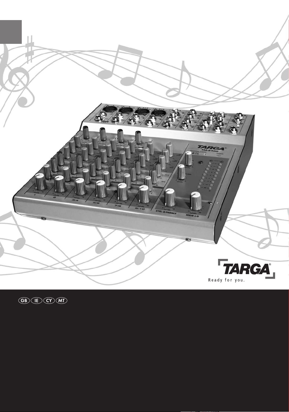
Sound Mixer
SouNd MixeR
Operation and Safety Notes
Page 2

Front Panel Connector Jacks
(see page 6)
Rear Panel
(see page 8)
Controls
(see page 12)
Master Control Panel
(see page 14)
Page 3

Safety Instructions
General
Before you use this device for the rst time, please read the following notes in this manual and heed
all warnings, even if you are familiar with handling electronic devices. Keep this manual safe for future
reference. If you sell the device or pass it on, it is essential you hand over this manual also.
Operating Environment
Position the device on a stable, even surface and do not place any heavy objects on the device.
The device is not for use in environments with a high temperature or humidity (e.g. bathrooms), and
must be kept free of dust.
Operating temperature and operating humidity: 5 °C to 35 °C, max. 85 % RH.
Always make sure that
• there is free circulation of air (do not place the device on shelves, on a thick carpet, on a bed, or
anywhere that obstructs the ventilation slots, and leave at least 10 cm clearance on all sides;
• no direct heat sources (e.g. heating) can affect the device;
• no direct sunlight or bright articial light reaches the device;
• contact with spray and dripping water and abrasive liquids must be avoided and the device should
never be operated near water, and it must especially never be immersed (do not place any objects
lled with liquids such as vases or drinks near the device);
• no re sources (e.g. burning candles) are placed on or near the device;
• no foreign bodies are introduced into the device;
• the device is not subject to any great temperature changes as this may cause moisture through con
densation and short-circuit;
• the device is not subject to excessive shocks and vibrations;
-
Power Supply
The power switch of this device does not fully disconnect the device from the mains.
The device consumes electricity in the Standby mode. In order to completely disconnect the device from
the mains, the power plug must be pulled out from the wall outlet. For this reason, the device should be
positioned in a way that assures a direct and unobstructed access to the wall outlet so that the power
plug can be immediately pulled out in an emergency situation. To avoid the danger of re if the device is
not going to be used for a long while (e.g. during holidays), it should always be disconnected from the
power socket. Before stormy weather when there is the danger of lightning, disconnect the device from
the power supply.
Use only the supplied power adapter to avoid overheating, deformation of housing, re, electric shock,
explosions and other dangers. Never connect this power adapter to other devices.
Page 4

TARGA TM-2100English
1
Cables
Always hold cables by the plug and never pull on the cable itself.
Never hold the power cord with wet hands as this may cause a short circuit or electric
shock.
Never place the device, heavy objects or furniture on the cable and take care that the
cord does not become trapped, especially at the plug and sockets. Never make knots in
the cable and do not tie it together with other cords. All cables should be positioned so
that nobody can trip over them or be obstructed by them.
A damaged power cord can cause a re or an electric shock. Inspect the power cord
from time to time. Never use adapter plugs or extension cables that don't comply with
the current safety regulations in your country, and don't modify any of the power cords
or electrical installations yourself!
Maintenance and Care
Servicing is required when this device has been damaged in any way, for example,
when the power plug, power cord or housing is damaged, when liquid or objects have
entered the device, when the product has been exposed to rain or moisture, when the
product does not work normally or if the product has been dropped. If you notice any
smoke, unusual noise or strange smells, switch off the device immediately and pull the
plug from the wall outlet. In this case the device should not be used further and should
be inspected by authorized service personnel. Please contact qualied personnel when
servicing is needed. Never open the housing of the device, the power adapter or the accessories. By opening the housing you endanger your life through risk of electric shock.
Only use a clean, dry cloth for cleaning and never use any abrasive liquids.
Never open the mixing console! Modications and repairs must be performed by authorized technicians or service personnel.
Do not attempt to open the housing of the device otherwise you will void your warranty.
Disposal of Old Devices
1. If the product is labelled with a crossed-out waste bin, it is subject to the European
Guideline 2002/96/EC.
2. All electric and electronic devices must be disposed of separately from household
waste at established bodies.
3. With the proper disposal of old devices you avoid damage to the environment and
your personal health.
4. For further information about proper disposal, contact your local government, disposal bodies or the shop where you bought the device.
Children
Electrical appliances do not belong in the hands of children! Do not allow children to use
electrical devices when not under supervision. Children may not comprehend the pres-
ence of potential risks. Small parts can represent choking hazards.
Keep the packaging away from children too to avoid the danger of suffocation
Page 5

TARGA TM-2100 English
2
Intended Use
This is a consumer electronics device. It may only be used for private use, not industrial
or commercial purposes.
Furthermore, the device may not be used outdoors or in tropical climates. Only connection cables and external devices may be used that comply with safety standards and the
electromagnetic compatibility and shielding quality of this device. This device fulls all
that relates to CE Conformity, relevant norms and standards. Any modications to the
equipment other than recommended changes by the manufacturer may lead to the result that these directives are not met any more. Only use the accessories recommended
by the manufacturer.
If you are not using the device within the Republic of Germany, you must observe the
regulations and laws in the country of use.
When connecting peripheral devices, make sure the cables are not too short and that
they don't force the connectors mechanically!
Use only the cart, stand, tripod bracket or table specied by the manufacturer or sold
with the product. When a cart is used, operate carefully to prevent the device from tipping over.
Noise Abatement
• According to international safety regulations the maximum permitted noise level is
100 dB.
• Using the loudspeakers/headphones at a higher sound volume can damage your
hearing and cause nuisance to your surroundings. The output voltage on the HEADPHONE jack can be over 150 mV and up to 1.5 V. It can therefore generate a
noise level that may damage your ears.
• The sound may distract your attention under dangerous circumstances or prevent
you from being aware of what is happening around you.
• Audio listening at high volume can harm the user’s auditory system.
• The use of unsuitable sound sources, non-shielded cables, devices with incompatible impedance values and improper signal level adjustments of the connected input
or output devices, as well as the mixing console, can lead to a higher audio output
signal and hearing damage.
CAUTION!
• High volume levels can harm the user’s auditory system and/or any connected
headphones or speakers.
• Turn all controls on the mixing console anti-clockwise to the minimum level
before powering it on.
• Always ensure that you set a suitable volume.
• For safety reasons, prior to connecting or putting on the headphones, always
double-check that the volume set on the mixing console will not harm your
ears.
CE Declaration of Conformity
This device has been tested and approved for compliance with the basic and other
relevant requirements of the EMC Directive 2004/108/EC, as well as the Low-voltage
Directive 2006/95/EC.
Page 6

TARGA TM-2100English
3
Table of Contents
Safety Instructions .......................................................................Inside manual cover
General ............................................................................................. Inside manual cover
Operating Environment..................................................................... Inside manual cover
Power Supply ................................................................................... Inside manual cover
Cables .............................................................................................................................1
Maintenance and Care ....................................................................................................1
Disposal of Old Devices ..................................................................................................1
Children ...........................................................................................................................1
Intended Use ...................................................................................................................2
Noise Abatement .............................................................................................................2
CE Declaration of Conformity ..........................................................................................2
Table of Contents ..........................................................................................................3
Introduction ....................................................................................................................4
Package Contents .........................................................................................................4
Features and Characteristics .......................................................................................5
Overview.........................................................................................................................6
Jacks and Controls ..........................................................................................................6
Getting Started ...............................................................................................................9
Installation Location .........................................................................................................9
Connecting Audio Devices.............................................................................................10
Connecting the Power Adapter ......................................................................................11
Powering-On the Mixing Console ..................................................................................11
Powering-Off the Mixing Console ..................................................................................11
Mixing and Processing the Audio Signals ................................................................12
Controls and Indicators of the Mixing Console ..............................................................12
Master Control Panel .....................................................................................................14
Mixing the Sound Signals ..............................................................................................15
Appendix ......................................................................................................................16
Practical Examples ........................................................................................................16
Connectors, Jacks and Polarity .....................................................................................19
Troubleshooting .............................................................................................................21
Technical Specications ................................................................................................22
Block Diagram ...............................................................................................................23
Important Warranty Information .................................................... Inside manual cover
Page 7

TARGA TM-2100 English
4
Introduction
Thank you for choosing this high-end TARGA TM-2100 mixing console. The TM-2100
presents 10 input channels for audio signals and mixes these on two channels to one
stereo signal. The input sound sources (4 x stereo, 2 x mono) can be mixed at the same
time with an EFX control (6 x EFX) and be fed as stereo signals to the EFX channel output. From there the stereo signal can be forwarded to an external sound effect device
(e.g. reverb effect) and then fed into the Return AUX input of the TM-2100.
Please check that delivery contents are complete using the list below.
Package Contents
First check whether all the parts are complete and undamaged. If any of the parts included in the delivery package are missing or damaged, please contact your dealer.
The following are included in your TARGA TM-2100 package contents:
1 TARGA TM-2100 mixing console
2 Power adapter for TARGA TM-2100
Page 8

TARGA TM-2100English
5
Features and Characteristics
• The TARGA TM-2100 mixing console has jacks for 10 input channels from which
you can mix 4 stereo and 2 mono channels on an EFX or collectively on the stereo
output MAIN OUTPUT.
• Via the CONTROL ROOM or HEADPHONES industry-standard jacks you can ei-
ther listen to the mixed master stereo signal or the signal input to the TAPE IN jacks
beforehand.
• The mixing console has two AUX SEND jacks and one AUX RETURN jack. Effect
processors and monitor equipment can be connected via the two independent AUX
jacks.
• Devices such as condenser microphones can be powered via the Phantom power
supply when optionally powered on via the microphone input.
• The mixing console has INSERT jacks for the input channels 1 and 2. Via these
jacks the signals of various effect processors can be fed to the individual channels.
• For channels 1 and 2 there are both XLR jacks for the connection of microphones
and also conventional TRS phone jacks. For input channels 7/8 there is a TRS
phone jack as well as an RCA jack (often also termed "Cinch"). These multiple audio
connectors enable you maximum exibility for connecting to many sound sources,
such as microphones, standard Line-Out output devices, stereo synthesizers, etc.
• Each channel has its own equalizer, via which you can raise or lower the low, mid
and high frequencies of the individual input devices independently from each other.
Page 9
TARGA TM-2100 English
6
Overview
Jacks and Controls
Your TARGA TM-2100 mixing console has multiple connector jacks for the different
sound sources (e.g. microphone, standard Line-Out output devices, stereo synthesizers, etc.) that you can comfortably mix and output via the stereo out jacks.
The following section describes the individual connectors of the mixing console.
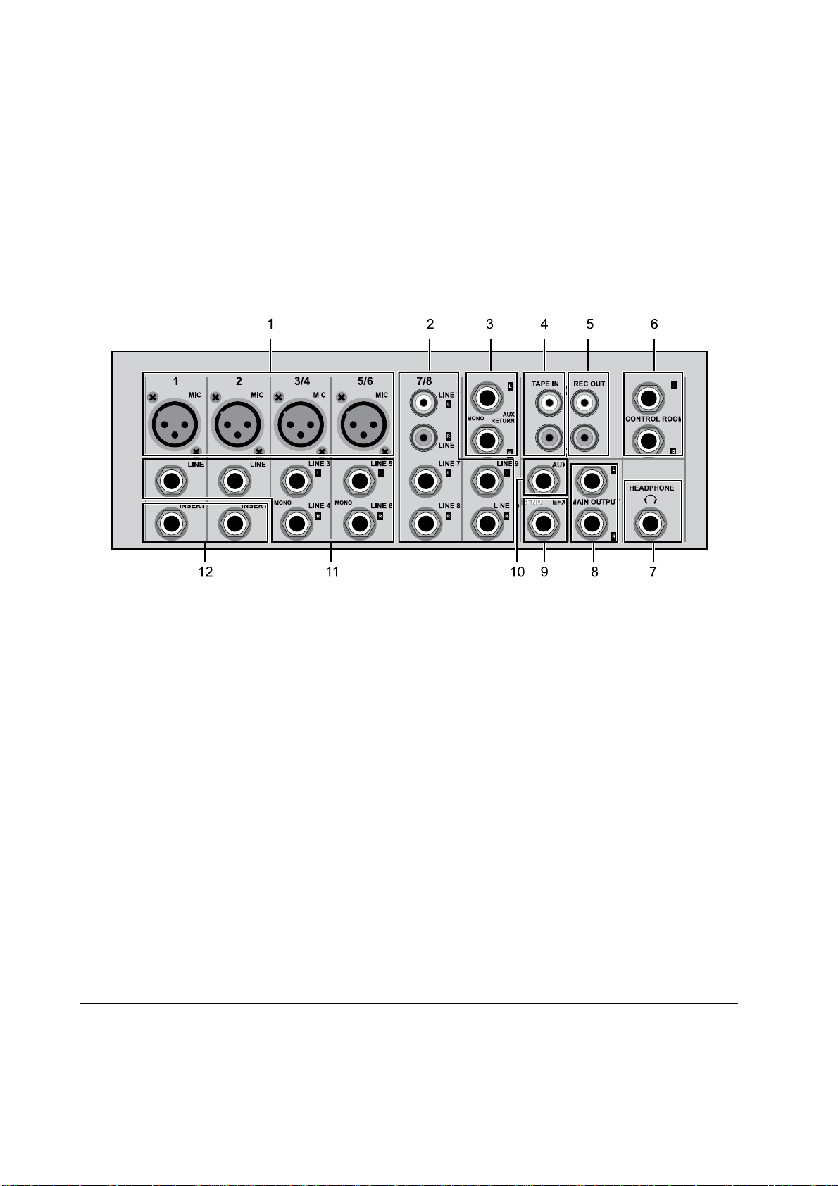
Front Panel
1 Microphone connectors
Here you can connect up to four microphones with balanced XLR connectors.
2 RCA/Cinch and phone-type jacks for channels 7/8 and 9/10 (LINE-IN)
These inputs serve as connectors for audio devices that send a signal level according to
LINE* standard. You can, depending on the available cable types, use cables with Cinch
(also termed RCA) or with conventional phone jack-type connectors.
WARNING: Never connect two devices at the same time to the same input channel. For
example, do not connect the rst to a Cinch input (2) and the other device via a phone
jack of the same channel.
3 AUX RETURN L (Mono), R phone jacks
These unbalanced phone jacks are for the connection of effects processors (reverb, delay, etc). They serve to receive the signals delivered from external devices that are then
redirected to the stereo bus.
Note: An additional stereo signal can be fed in via these jacks as required. If you only
use one of the two inputs (mono signal), this mono signal will be forwarded to both the
stereo channels (L, R).
* The LINE standard is an audio industry standard allowing a hassle-free inter-connection of different devices featuring audio inputs and outputs. All devices that support this standard have input and output jacks that use standardised
impedances and signal levels. This allows a fast and easy cabling without having to perform any level and impedance
matching rst.
Page 10

TARGA TM-2100English
7
4 TAPE IN (L, R) input jacks
These unbalanced Cinch inputs (also termed RCA jacks) serve to connect stereo sound
sources such as tape decks, CD players, etc. You can then adjust the signal level of
the connected sound sources via the TAPE control (30) of the master control panel and
listen to the mixing console.
5 REC OUT (L, R) output jacks
The mixed signal from the mixing console is delivered to this jack. Here you can connect a suitable recording device to record the mixed signal. You can regulate the levels
to these jacks via the MAIN L/R control (27) of the master control panel.
6 CONTROL ROOM out (phone jacks)
These unbalanced Mono phone jacks are for listening to the mixed signals. Here, for example, you can connect studio speakers. You can adjust the level of the mixed signals
to these jacks via the CTRL-R/PHONES control (28) of the master control panel.
7 (HEADPHONE) headphone out
This unbalanced stereo phone jack serves as the connection for headphones. You can
adjust the levels of the mixed signals to this jack via the CTRL-R/PHONES control (28)
of the master control panel.
8 MAIN OUTPUT stereo out (phone jacks)
These unbalanced Mono phone jacks are for the connection of external devices, such
as for example, ampliers. You can adjust the levels of the mixed signals to these jacks
via the MAIN L/R control (27) of the master control panel.
9 EFX out (phone jacks)
This unbalanced Mono phone jack is for the connection of effect devices. Here you can
pick up the pre-mixed EFX signal that you have adjusted via the EFX control (20) of the
individual channels.
10 AUX-out (phone jacks)
This unbalanced Mono phone jack socket is for the connection of monitor equipment
and other devices. Here you can pick up the pre-mixed AUX signal that you have adjust-
ed via the AUX control (19) of the individual channels and after processing through the
external device as required can again be fed in via the AUX RETURN jack sockets (3).
11 Phone jacks for channels 1,2, 3/4 and 5/6 (LINE-IN)
These balanced inputs 1 and 2 as well as the unbalanced inputs 3/4 and 5/6 are connectors for audio devices.
WARNING: Never connect a microphone and another device at the same time to the
same input channel. For example, do not connect the microphone to the mic input (1)
and the other device via a phone jack (11) of the same channel.
12 INSERT phone jacks
What's special about these phone jacks is that they are unbalanced and can be used as
inputs and outputs. Each of these jacks can be fed between the pre-amplier and the
High Pass Filter of the relevant input channel.
Page 11

TARGA TM-2100 English
8
Alternatively they can be used to output these channels independently from each other
to devices such as graphic equalizers, compressors and noise lters. This is a TRS (TipRing-Sleeve) phone jack, that can be used bi-directionally.
WARNING: To be able to connect devices to the INSERT jack you need a special cable.
This can be bought as an accessory from any dealer. The pin conguration is as follows:
13 Power adapter connector (AC ADAPTOR IN)
Here you connect the supplied power adapter.
IMPORTANT: The plug must be secured into the jack. To do this, rst plug in and gently
turn the outside metal ring clockwise till tight.
WARNING: When operating your TARGA TM-2100 mixing console, use only the sup-
plied adapter, and never use the adapter to feed other devices.
14 On/Standby switch (POWER ON/OFF)
Use this switch to power on the mixing console or to set it on power-saving Standby.
Output signal to external devices (tip)
Incoming signal from external devices (ring)
Shielding (earth)
(sleeve)
To input of external devices
From output of external
devices
WARNING! The output signal is delivered reverse-phased to the INSERT jack. If you
connect to an external effects processor, this is no problem. However, if you connect an
external device, this can lead to phase shifting and signal interference.
Rear Panel
Page 12

TARGA TM-2100English
9
Getting Started
You can use your TARGA TM-2100 mixing console for the following three applications:
1. Signal processing
Signal processing includes boost, level adjustment, frequency characteristics as well as
the mixing of effects.
2. Signal distribution
Signal distribution includes the allocation of the signal to the output connector jacks for
effect processors and studio loud speakers, distribution on various recording tracks or
amplier channels, signal-feeding to the control room, etc.
3. Signal mixing
This includes the volume controls, frequency curve adjustment and the stereo balance
that come from the signals of the various sound sources. Furthermore the level monitoring of the mixed output signal is made here, in order to feed external devices such as
ampliers, recording devices and frequency switches.
In the following section you will learn how to unpack, connect and operate your TARGA
TM-2100. At the end of the manual you will nd helpful tips on mixing and adjusting
signals.
Installation Location
Before you connect your mixing console, you should select a suitable location. On the
one hand it should be comfortable to operate and on the other hand, the numerous connected cables and devices should never be in anyone's way.
Take special care when positioning the cables that nobody can trip over them.
All devices connected to the mixing console must be properly grounded. For your own
protection and to avoid background noise and crackling sounds, you should not modify
or eliminate the grounding of the device or of the cable.
Position the mixing console near a power socket so that be easily supplied with electricity, but at the same time the plug can be quickly pulled out in an emergency. Also take
care that the outlets to the connectors of all cables and devices are easy to reach as
before.
Protect the mixing console from direct sunlight and do not place it near any heat sourc-
es (heating, windows, on or beneath the ampliers, etc.).
The safest place is in a rack or a suitable stand (available as an accessory from any
dealer). If you want to place your mixing console on a table, you should carefully tie
together all connected cables to the table leg or similar (e.g. with sticky tape or cable
wire) to avoid that the device falls down through being mechanically pulled onto one of
the cables.
Page 13

TARGA TM-2100 English
10
Connecting Audio Devices
After you have unpacked your device and located it in a suitable position, you can connect your audio devices. In the following gure you will nd an example of which devices you can connect to the various jacks. The vast number of jacks however permits
so many connection possibilities that we are unable to go into detail on all the different
versions.
In the annex you will however nd the allocation of the jacks as well as the possible
connectors with some examples of devices and cables that typically occupy such con-
nector plugs. You will nd some practical examples of use in the annex.
You can nd details of the available connector jacks in the "Jacks and Controls" section
on page 6.
Take special care when positioning the cables that nobody can trip over them. If you
want to place your mixing console on a table, you should carefully tie together all connected cables to the table leg or similar (e.g. with sticky tape) to avoid that the device
falls down through being mechanically pulled onto one of the cables.
Page 14

TARGA TM-2100English
11
Connecting the Power Adapter
1. Connect the power adapter cable to the AC ADAPTOR IN jack on the rear of the
mixing console.
2. Gently turn the outside metal ring till tight to x the plug in the jack.
3. Switch the POWER switch to the OFF position and turn all controls on the mixing
console anti-clockwise to the minimum level.
CAUTION! Always switch the mixing console OFF before you connect to the power
supply. Likewise adjust all controls on the mixing console to minimum otherwise it may
produce unexpected volume levels that may damage your hearing or loudspeakers or
other connected audio devices.
4. Connect the other cable of the power adapter to a live wall outlet.
WARNING: Take care when positioning the power cable of the power adapter that nobody can trip over it.
TIP: When not using the audio mixer for a long time, we recommend that you disconnect the power adapter from the mains in order to cut any power consumption and to
protect the environment.
Powering-On the Mixing Console
1. Turn all the controls on the mixing console anti-clockwise to the minimum level.
2. Power on the mixing console. Do this by toggling the POWER switch (14) that is
located on the back of the device to the ON position.
CAUTION! Before powering on adjust all controls on the mixing console to minimum,
otherwise it may produce unexpected volume levels that may damage your hearing or
loudspeakers or other connected audio devices.
Powering-Off the Mixing Console
1. Turn all the controls on the mixing console anti-clockwise to the minimum level.
2. Power off the mixing console. Do this by toggling the POWER switch (14) that is
located on the back of the device to the OFF position.
Page 15

TARGA TM-2100 English
12
Mixing and Processing the Audio Signals
You can comfortably process the signals of the various sound sources with the help of
the numerous controls on the mixing console.
At rst sight, so many potentiometers can look a little daunting. Luckily however there
are only 6 or 7 different controls that are repeated for the various channels. In the fol-
lowing you will nd an overview of these controls.
Controls and Indicators of the Mixing Console
In the following gure you will nd an overview of the controls and displays for channels
1-10. Their function is identical for the various channels.
Controls for the Individual Channels
15 PEAK indicator
Measures the level of the post-EQ signal and lights red when the level reaches 5dB
below the clipping level. For stereo channels with XLR jacks (3/4 and 5/6) it measures
the post-EQ level and the pre-amplied mic levels. The display lights red again if one of
these levels reaches 5dB below the clipping level.
16 TRIM (Gain)
This control is for adjusting the input level. Set it so that the PEAK indicator (15) lights
only briey at the maximum input level. This will enable you to achieve a balanced ad-
justment between signal/noise ratio and dynamic range.
The scale from -50 to -6 dB denotes the input levels for the MIC jacks (for microphones)
for channels 1 and 2. The scale from -50 to -10 dB denotes the input levels for the MIC
jacks (for microphones) for channels 3/4 and 5/6. However, if you connect devices with
LINE standard output to the LINE jack, the scale is from -30 to +14 dB for channels 1
and 2 and from –20 to +20 dB for channels 3/4 and 5/6.
Page 16

TARGA TM-2100English
13
17 Switch for High-Pass Filter
This switch allows you to toggle the high-pass lter on or off. Frequencies under 75 Hz
are cut.
Note: There is no high-pass lter when using stereo LINE inputs (regardless of the
switch setting).
18 Equalizer
The mixing console has a 3-band equalizer, via which you can amplify or attenuate the
low, mid and high frequencies individually for each of the channels. This means you
can adjust the desired sound characteristics for every channel independently from each
other.
Turn all the controls of a channel to the middle position ("0" value) to maintain the original frequency response of the connected devices.
Turn the HF, MF or LF control to the right to boost the high, mid or low frequencies.
Turn the HF, MF or LF control to the left to attenuate the high, mid or low frequencies.
The following table gives details of the EQ type for the different frequency bands and
the possible boosting/cutting.
Controls Curve Base frequency Maximum boost/cut
LF Shelving 80 Hz
±12 dB
MF Peaking 2.5 kHz
±12 dB
HF Shelving 12 kHz
±12 dB
19 AUX controls
With the AUX controls you can output the channel signals on the AUX jack (10).
Turn the AUX control clockwise from the left to increase the AUX level (AUX jack) grad-
ually.
Note: The signal to the AUX jack is a pre-fader signal. This means that it cannot be adjusted through the channel fader (22).
20 EFX controls
With this potentiometer you can adjust the EFX output of the preset signal level. As
these controls are arranged behind the channel fader, their settings affect the level that
you have preset using the relevant channel fader.
21 PAN/BAL control
PAN (Mono channel 1 and 2)
The PAN controls determine the balance of the Mono signal on the Stereo L and R outputs.
Turn the PAN control anti-clockwise to output the sound of the relevant channel only
from the left loudspeaker.
Turn the PAN control clockwise to output the sound of the relevant channel only from
the right loudspeaker.
Page 17

TARGA TM-2100 English
14
BALANCE (Stereo channels 3/4, 5/6, 7/8 and 9/10)
The BALANCE control is to adjust the balance between the left (L) and right (R) stereo
channel. Signals that are fed to input L (left) will be directed to the left Stereo bus (L).
Signals that are fed to input R (right) will be directed to the right Stereo bus (R).
22 Channel Fader
This control adjusts the output level of the signal input to one single channel. This enables you to adjust the volume balance between the individual channels.
Note: To reduce noise, turn the controls for all channels not in use anti-clockwise (to the
minimum level).
Attention!
If you need to re-adjust the equalizer setting, it is also recommended that you correct the level by using the TRIM adjustment and monitor the PEAK indicator.
Once you have adjusted the channel level according to the instructions given on
page 12 and the PEAK indicator, we recommend that you do NOT set the channel fader to its maximum value (position 10) otherwise, this setting might lead to
sound distortion depending on the instrument connected. It is recommended that
you set the channel fader from the center position (position 5) up to approx. position 8 maximum.
Master Control Panel
In the Master Control Panel you can nd the controls
that simultaneously affect all channels, the level indicators and the button for toggling the phantom power on
and off for the condenser microphones.
23 PHANTOM POWER indicator
This indicator lights when you have powered on the
48V phantom power for the condenser microphones.
24 PHANTOM POWER switch
Here you power on the phantom power as required. If
you set this switch on, the phantom power is supplied
to all XLR mic inputs (channels 1, 2, 3/4, 5/6). You
must do this when you have connected one or more
condenser microphones to the mixing console.
WARNING: When you set this switch on, a DC volt-
age of +48 V is supplied to pins 2 and 3 of the XLR mic
inputs. Leave this switch off when you do not need
the phantom power, otherwise it may cause humming or damage to devices if an unbalanced device or ungrounded transformer is connected.
The switch can however be switched on without problem when you, for example, connect balanced dynamic microphones.
To avoid damage to loudspeakers, switch all ampliers (or powered speakers) off before
turning this switch on or off.
25 POWER indicator
This indicator lights up when your TARGA TM-2100 mixing console is powered on.
Page 18

TARGA TM-2100English
15
26 Level indicators
By means of these indicators you can control the signal level fed to the Stereo bus. The
"0" value corresponds to a normal output level. The indicator lights red when the signal
level has reached or exceeded the maximum clipping level. From this level the sound
signal can be distorted.
27 MAIN L/R Master Fader (Stereo overall signal control)
Here you can adjust the level of the supplied stereo signals to the MAIN OUTPUT (8)
jacks. This is the already-mixed signals from all channels.
28 CTRL-R/PHONES control
Here you can control the level of the supplied signals to the HEADPHONE (7) and
CONTROL ROOM L and R (6) jacks. It serves to adjust the listening volume for the
headphones or studio loudspeaker.
29 AUX RETURN controls
Here you can set the levels of the mixed L/R signal that is directed from the (3) AUX
RETURN (L (MONO) and R) jacks to the Stereo bus.
Note: If you feed in a pure Mono signal via the RETURN L (MONO) jack, the signal will
be equally output on both channels of the Stereo bus (L and R).
30 TAPE control
Here you can adjust the levels of the signal that is directed from the TAPE IN (4) jacks
on the Stereo bus.
Mixing the Sound Signals
Before you can mix the signals of the different sound sources, you must correctly set the
levels of the individual input signals (channels). By doing this you will avoid overboosting and sound distortion.
1. Turn the LEVEL (22) control of the relevant channel to the middle position.
2. Turn the TRIM (16) and AUX (19) controls anti-clockwise as far as you can and turn
the HF, MF and LF of the Equalizer to the middle position.
3. Connect the desired sound source to a suitable input jack of the channel.
4. Start playback on the sound source. If this is an instrument, play a song. Or say
something if you have connected a microphone. It is important here that the play-
back takes place with the same volume as you want to later use to mix.
5. Turn the TRIM control (16) clockwise till the PEAK indicator (15) lights. Then turn
the control gently anti-clockwise till the PEAK indicator (15) no longer lights continu-
ously.
6. Adjust the HF, MF and LF controls of the Equalizer (18) to set the desired sound
characteristics for the bass, mid and high tones.
7. After setting the sound characteristics it may be necessary to correct the levels us-
ing the TRIM control (16).
Page 19

TARGA TM-2100 English
16
Appendix
Practical Examples
In the following pages you will nd practical examples of use for your mixing console.
Playing Music on the Computer
To play former recordings or audio signals on your computer you can connect the suit-
able device (e.g. tape deck) to your mixing console and connect it to the LINE-In jack of
your computer's sound card. Alternatively you can use the recording possibilities of the
computer to compile radio plays, remixes etc. with your TARGA TM-2100.
If your sound source has a LINE standard output (if necessary read the manual of the
corresponding device), connect this using a stereo cable with a phone jack to one of the
LINE jacks (11) on the mixing console.
If your device uses a Cinch cable (red and white plugs), connect the Cinch cable to the
same-coloured TAPE IN jacks (4) on the mixing console.
Then you can connect the MAIN OUTPUT output (8) using a suitable cable to the sound
card input of your computer.
Page 20

TARGA TM-2100English
17
Simple Recording Studio
For this you can connect all microphones to the mic inputs and the instruments to the
Mono (e.g. E-guitar) or Stereo phone jacks (e.g. synthesizer). Connect the recording
device (e.g. DAT) to the REC OUT stereo output (5).
To listen to the results connect the CONTROL ROOM jacks (6) to the studio loud speak-
ers or the HEADPHONE jack (7) to a headphone set.
Page 21

TARGA TM-2100 English
18
Simple Concert / DJ Conguration
This setting is very similar to the previous one. For output, however, you connect the
mixing console to an amplier and not to a recording device.
As a DJ you simply replace the stereo instrument for a tape deck, CD player or similar
device.
If necessary you can additionally connect an external effect processor to the EFX (9)
and LINE 9/10 (2) jacks.
Page 22

TARGA TM-2100English
19
Connectors, Jacks and Polarity
When connecting your instruments, microphones and other sound sources you must
use the correct types of cables and connectors. In the following you will nd an overview
of connectors and jacks that your TARGA TM-2100 supports.
XLR-type connector for microphones (balanced operation*)
1 Earth
2 Hot (+)
3 Cold (-)
Jack Connector
* For unbalanced operation pins 1 and 3 must be short-circuited.
6.3mm phone jack connector (Mono)
to be used for: unbalanced Mono phone jacks
Tip (Signal)
Sleeve (Shielding/earth)
Tip (Signal)
Sleeve (Shielding/earth)
Strain relief clamp
6.3mm phone jack connector (Stereo)
to be used for: balanced Mono phone jacks (Line 1, Line 2), unbalanced Stereo phone
jacks (Phones), Insert I/O
Tip (Signal), left sound channel
Ring (Signal), right sound channel
Sleeve (Shielding/earth)
Tip (Signal), left sound channel
Ring (Signal), right sound channel
Sleeve (Shielding/earth)
Strain relief clamp
Page 23

TARGA TM-2100 English
20
Cinch connector (red, white) for TAPE IN input, Stereo inputs of the channels 7/8 and
REC OUT Stereo output jacks for recording devices.
Page 24

TARGA TM-2100English
21
Troubleshooting
With the numerous connector jacks and controls of the TARGA TM-2100 it is not easy
for a newcomer who may even nd themselves lost in the jumble of cables. Read the
following section and if necessary the relevant section on connectors or operation of the
controls again, and try to solve any problems with these basic solution ideas.
Problem Possible cause Solution
No sound
The mixing console
is powered off.
Power on the mixing console. Press the POW-
ER switch on the back panel of the device.
Connect the power adapter rmly to the mix-
ing console and a properly-functioning power
socket.
The power adapter
may not be properly
connected.
Connect the power adapter rmly to the mixing console and a properly-functioning power
socket.
Sound source connected wrongly.
Connect the sound source (microphone, instrument, input device) to the correct input
jack.
Control on minimum.
Adjust the input levels with the corresponding
TRIM and LEVEL controls of the channels to
which the corresponding devices have been
connected.
Also adjust the output level of the mixing
signal using the MAIN L/R control (5) on the
lower right of the mixing console.
Humming or
crackling noises
Faulty grounding
It is possible that the earth wire of one or
several connectors or cables is loose. Pull the
connectors out of the jacks one at a time to
nd out which cable is causing the noise disturbance. Use another cable for connection.
Turn the TRIM and LEVEL controls of all input
channels on which NO devices are connected
anti-clockwise as far as they will go.
You can only
hear one stereo
channel
Wrong balance
Turn the PAN or BALANCE controls of the
corresponding channels until you can hear the
sound on both stereo channels.
Sound very distorted
Signal overboost
Check the level indicators (4). Adjust the out-
put level (MAIN L/R control in the lower right
corner) so that the indicator does not hit the
red area.
Adjust the levels of the individual input channels (TRIM controls) so that the PEAK indicator of each channel only lights occasionally,
not continuously.
Page 25

TARGA TM-2100 English
22
Technical Specications
EFX control:
The input sound sources (4 x stereo, 2 x mono) can be mixed at the same time with an
EFX control (6 x EFX) and be input as stereo signals on the EFX channel output. From
there the stereo signal can be input to an external sound effect device (e.g. echo effect)
and then fed into the Return AUX input of the TM-2100.
In/outputs: 2 Mono, 4 Stereo inputs
Channel EFX output to loop in an effect unit
Return AUX input for feedback from effect unit
4 balanced mic inputs
Channel 1 and 2 with Insert jack to loop in an ex-
ternal device
Stereo output
Headphones out
Peak control indicator: (Peak LED) for channels 1/2/3/4/5/6, 5dB before
clipping level
Control indicator: (2 x 10 LEDs) for Stereo output signal
Phantom power: (+48V) for channels 1/2/3/4/5/6 to connect con-
denser microphones
Frequency band: +0/-1dB, 20Hz-20kHz
Total Harmonic Distortion (THD): 0.1% @1kHz (Output +14dBu)
Hum & Noise: E.I.N (Equivalent Input Noise) -126dBu (0dBu =
0,775V)
Residual Noise Input/Output -95dBu
Aux Send Out -85dBu
EFX Send Out -85 dBu
Crosstalk (1kHz): > 70 dB
Equalizer: Hi: 12kHz, +/-12dB+/-2dB
Mid: 2.5kHz, +/-12dB+/-2dB
Low: 80Hz, +/-12dB+/-2dB
HPF (High Pass Filter): 75Hz
Dimensions / Weight: 250 x 78 x 304 mm (W x H x D) / 2.8kg
Power consumption: 30 W
Power supply: 230 V
External power adapter:
Type of power adapter: Targa TM-2100
Manufacturer: Targa
Input voltage: 230VAC, 50Hz, 25W
Output voltage: 2*18VAC, 400mA, 50Hz
Dimensions: 8cm x 5,6cm x 5cm (LxWxH)
Weight: 570 g
Page 26

TARGA TM-2100English
23
Block Diagram
Page 27

TARGA TM-2100 English
24
Manufacturer:
TARGA GmbH
Lange Wende 41
59494 Soest
Germany
Page 28

Important warranty
information
Dear Customer,
Thank you for purchasing a TARGA product.
Please carefully read through the enclosed documentation or online help before putting your
Targa product into service. If you have a problem, which can’t be solved in this way, please
contact our hotline.
If the problem cannot be solved over the phone, you will be given a reference number
(RMA), which you should enclose together with a copy of the proof of purchase. After you
have packaged the unit safe for transport and in plain packaging, please send it for warranty
processing, with the RMA noted on the outside of the package, to the address given to you
by our hotline employee. After receiving the unit we will correct the manufacturing and
material defect free of charge.
Up-to-date information and answers to the most frequently asked questions are available on
the internet from:
www.targa-online.com
This guarantee is valid in the UK.
Your statutory guarantees from the seller are in addition to this warranty and are not limited
by it.
H o t l i n e n u m b e r :
0 2 0 7 - 3 6 5 0 7 4 4
( P le a s e h a v e yo u r
s e ri a l nu m b e r t o h an d ! )
36 month warranty from
date of purchase
Manufacturer: TARGA GmbH, Postfach 2244,
D-59482 Soest
www.targa-online.com
UK 1191514
Important warranty
information
Dear Customer,
Thank you for purchasing a TARGA product.
Please carefully read through the enclosed documentation or online help before putting your
Targa product into service. If you have a problem, which can’t be solved in this way, please
contact our hotline.
If the problem cannot be solved over the phone, you will be given a reference number
(RMA), which you should enclose together with a copy of the proof of purchase. After you
have packaged the unit safe for transport and in plain packaging, please send it for warranty
processing, with the RMA noted on the outside of the package, to the address given to you
by our hotline employee. After receiving the unit we will correct the manufacturing and
material defect free of charge.
Up-to-date information and answers to the most frequently asked questions are available on
the internet from:
www.targa-online.com
This guarantee is valid in the Ireland.
Your statutory guarantees from the seller are in addition to this warranty and are not limited
by it.
H o t l i n e n u m b e r :
0 1 - 2 4 2 1 5 8 3
( P le a s e h a v e yo u r
s e ri a l nu m b e r t o h an d ! )
36 month warranty from
date of purchase
www.targa-online.com
Manufacturer: TARGA GmbH, Postfach 2244,
D-59482 Soest
Ireland 1191515
 Loading...