


Targa Systems Division
Series 3 SATA
Technical Reference
and
Installation Guide
Targa Document 32003375
Revision Rev 3
Date October 2008
Targa Systems Division
L-3 Communications Canada Inc.
2081 Merivale Road
Ottawa Ont
Canada K2G 1G9
Tel: 613.727.9876
Fax 613.727.1705

TARGA SYSTEMS
S3 SATA Installation Guide 32003375 Rev 3
i
Revision History Table
Rev 1 Initial Release November 2007
Rev 2 MTBF Data added – Section 2.6 April 2008
Rev 3 Minor edits & corrections October 2008

TARGA SYSTEMS
S3 SATA Installation Guide 32003375 Rev 3
ii
Table of Contents
1.0 Introduction ....................................................................................................................... 1
1.1 Scope.................................................................................................................................. 1
1.2 DTU Overview .................................................................................................................. 1
1.3 Model Numbers ................................................................................................................. 1
2.0 Specifications .................................................................................................................... 2
2.1 SATA Interface ................................................................................................................. 2
2.2 Physical Characteristics .................................................................................................... 2
2.3 Unit Connector .................................................................................................................. 2
2.4 Environmental Conditions................................................................................................. 4
2.5 PC Card (FLASH ATA).................................................................................................... 4
2.6 Reliability Performance .................................................................................................... 4
2.7 Maintainability / Logistics Support .................................................................................. 4
3.0 SATA Operations ............................................................................................................. 5
3.1 General Operation Considerations ................................................................................... 5
3.1.1 Targa SATA Holder – General Operation Overview........................................................ 5
3.2 PC Card Handling ............................................................................................................. 6
4.0 Warranty & Repair ........................................................................................................... 7
Table 1 Model Numbers ................................................................................................................1
Table 2 Unit Connector ................................................................................................................. 2
Figure 1 DTU - Internal Mount Outline Dimensions ..................................................................... 3
TARGA SYSTEMS
S3 SATA Installation Guide 32003375 Rev 2
1
1.0 Introduction
1.1 Scope
This manual describes the installation and operational features of the Targa Series 3 Serial
ATA (SATA) Holder System (HS).
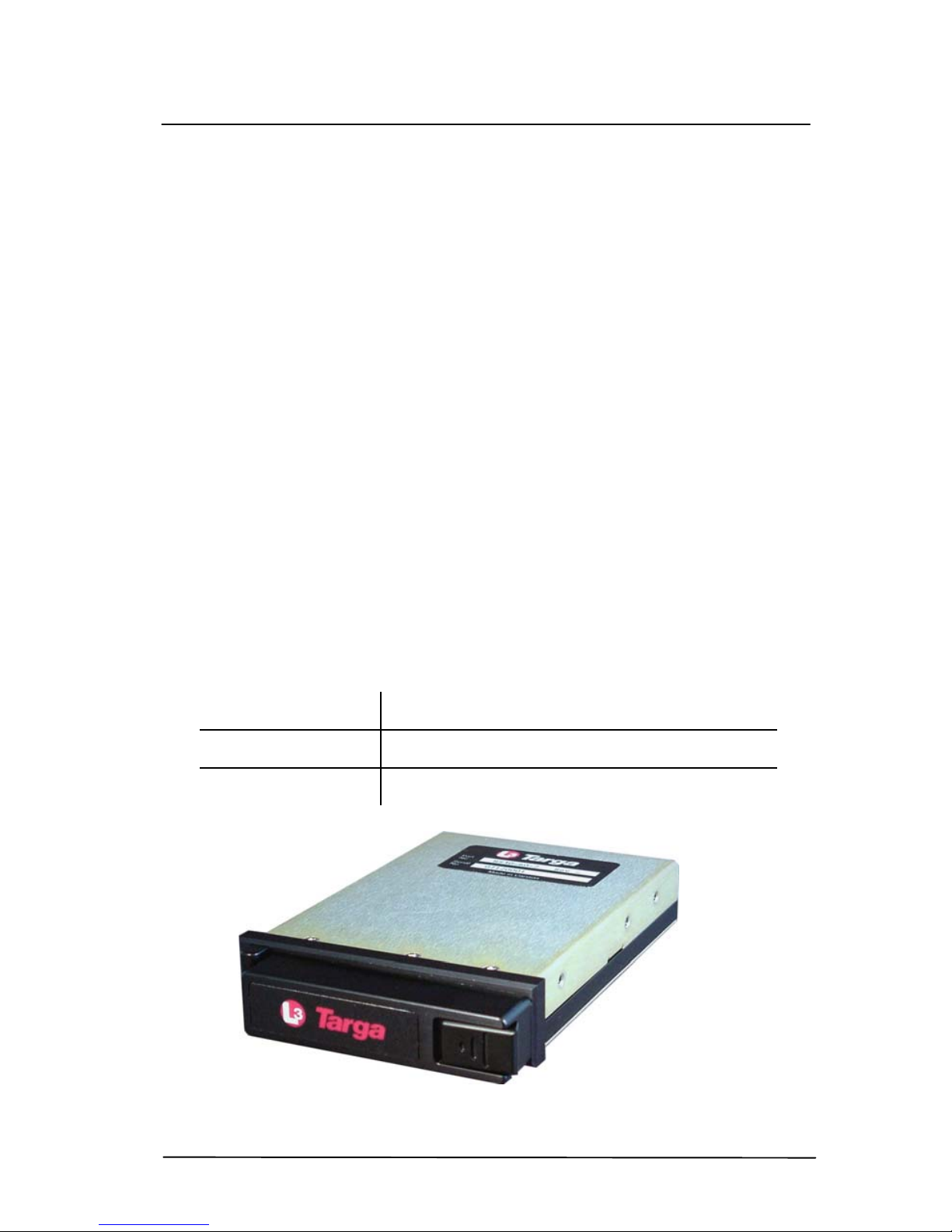
1.2 Overview
The Series 3 HS (Holder System) is a compact, self contained system, designed to store and
retrieve data from industry standard PC Card ATA (previously PCM CIA/ATA) FLASH
memory cards, via industry standard SATA 1 interface.
The internal mount Holder System is designed to fit into a 3.5" floppy bay and operate from a
5Vdc power supply.
The PC Card access door is opened by simply depressing the right side door latch slightly
towards the centre, requiring thumb or finger pressure only . This action releases the door lock
mechanism and as the door is opened, an optical sensor is tripped and the interface performs a
power shutdown of the PC Card to support “hot swap” operations.
Once the door is open the PC Card is inserted through the front panel card slot and gently
pushed into place. Conversely the PC Card is removed by depressing the card eject button
immediately beside the card slot.
Industry standard "FLASH / ATA " PC Cards provide a reliable, removable means for
transporting data between the mission platform based DTU and any ground based computer
system equipped with a PCMCIA socket and socket services software.
1.3 Model Numbers
Models
Description
HS30-60-2
Series 3 SATA Internal Mount Holder
SSD-PcccI-3500
PCMCIA/ATA Card CCC = Card Capacity
 Loading...