

Page 1

NNootteebbooookk CCoom
mppuutteerr
UUsseerr’’ss M
Maannuuaall
G797001
Page 2

Page 3

Preface
Copyright 1999
All Rights Reserved.
Manual edition, August, 1999 Document Number G797
The information in this document is subject to change without prior
notice in order to improve reliability, design and function and does not
represent a commitment on the part of the manufacturer.
In no event will the manufacturer be liable for direct, indirect, special,
incidental, or consequential damages arising out of the use or inability
to use the product or documentation, even if advised of the possibility
of such damages.
This document contains proprietary information protected by
copyright. All rights are reserved. No part of this manual may be
reproduced by any mechanical, electronic, or other means in any form
without prior written permission of the manufacturer.
Trademarks
Phoenix is a trademark of Phoenix Technologies Ltd. CardSoft is a
trademark of SystemSoft Corporation. AutoCAD and Autoshade are
trademarks of Autodesk, Inc. IBM, OS/2, and VGA are trademarks of
International Business Machines Corp. Lotus, 1-2-3, and Symphony
are trademarks of Lotus Development Corp. Windows, Word, MSDOS, and Microsoft are trademarks of Microsoft Corp. VESA is a
trademark of Video Electronics Standards Association.
Other product names mentioned herein are used for identification
purposes only and may be trademarks and/or registered trademarks of
their respective companies.
Limitation of Liability
While reasonable efforts have been made to ensure the accuracy of
this manual, the manufacturer and distributor assume no liability
resulting from errors or omissions in this manual, or from the use of
the information contained herein.
Page 4

ii
This page is intentionally blank
Page 5

iii
Table of Contents
Chapter 1: Introduction-------------------------------------------------1
Welcome to the Notebook PC --------------------------------------------------1
Unpacking the Notebook --------------------------------------------------------2
Accessories and Optional Devices---------------------------------------------2
Getting to Know Your Computer ----------------------------------------------3
Opening the LCD Panel---------------------------------------------------3
Front Panel ------------------------------------------------------------------6
Right Panel------------------------------------------------------------------7
Left Panel--------------------------------------------------------------------8
Rear Panel-------------------------------------------------------------------9
The Bottom Panel--------------------------------------------------------11
Preparing the Notebook for Transport---------------------------------------12
Chapter 2: Getting Started-------------------------------------------13
Operating Environment-------------------------------------------------------- 13
Connecting to a Power Source------------------------------------------------ 13
Connecting the AC Adapter-------------------------------------------- 13
Turning On Your Notebook Computer-------------------------------------- 15
About the ROM BIOS--------------------------------------------------- 15
About the Power-On Self Test----------------------------------------- 15
Resetting the System-----------------------------------------------------16
Adjusting the Brightness------------------------------------------------ 16
Operating on Battery Power --------------------------------------------------17
Inserting and Removing the Battery Pack---------------------------- 17
Charging the Battery Pack---------------------------------------------- 18
A Word about Ergonomics---------------------------------------------------- 19
Chapter 3: Using the Notebook Computer ---------------------21
The LCD Display ---------------------------------------------------------------21
Adjusting the LCD Screen Display -----------------------------------21
A Tour of the Notebook’s Keyboard ---------------------------------------- 22
Windows 95/98 Keys----------------------------------------------------23
The Function Keys------------------------------------------------------- 25
The Cursor Keys ---------------------------------------------------------25
Embedded Numeric Keypad -------------------------------------------25
The TouchPad-------------------------------------------------------------------26
Using the TouchPad ----------------------------------------------------- 26
Page 6

iv
TouchPad Precautions--------------------------------------------------- 27
Connecting an External Tracking Devices ---------------------------------27
Data Storage and Retrieval---------------------------------------------------- 27
The Floppy Disk Drive-------------------------------------------------- 27
The Removable HDD Module -----------------------------------------28
The CD-ROM ------------------------------------------------------------------- 29
Features of the CD-ROM Module------------------------------------- 29
Precautions for Handling CD-ROM Discs---------------------------30
Loading a Disc------------------------------------------------------------ 30
The Multimedia Sound System-----------------------------------------------31
IR Communication -------------------------------------------------------------32
PCMCIA Cards and Expansion Sockets------------------------------------33
Inserting a PCMCIA Card----------------------------------------------33
Power Saving Modes-----------------------------------------------------------34
The AC Adapter----------------------------------------------------------------- 34
The Battery Power System----------------------------------------------------35
Removing the Battery Pack---------------------------------------------35
Preparing the Battery Pack for Use -----------------------------------35
Automatic Battery Pack Charging Function------------------------- 36
Battery Status -------------------------------------------------------------37
Battery Low Warning ---------------------------------------------------39
Small Battery for the Real Time Clock ------------------------------- 40
Power Management Modes --------------------------------------------------- 41
How to Suspend ----------------------------------------------------------42
How to Resume----------------------------------------------------------- 43
Power Management Summary-----------------------------------------43
The APM Interface------------------------------------------------------- 44
Chapter 4: Connecting Peripheral Devices --------------------45
External Keyboard/Numeric Keypad----------------------------------------45
External Monitor---------------------------------------------------------------- 46
Parallel Printer------------------------------------------------------------------- 46
Serial Devices ------------------------------------------------------------------- 47
Audio Sources and Output Devices------------------------------------------ 48
Port Replicator ------------------------------------------------------------------49
USB Device---------------------------------------------------------------------- 49
TV Out---------------------------------------------------------------------------- 49
Installing Optional Devices --------------------------------------------------- 50
Chapter 5: Running BIOS Setup-----------------------------------53
Introduction---------------------------------------------------------------------- 53
Page 7

v
Navigating through BIOS Setup----------------------------------------------53
Accessing the BIOS Setup Program----------------------------------------- 53
Item Specific Help ------------------------------------------------------- 54
The Menu Bar ------------------------------------------------------------------- 54
The Legend Bar -----------------------------------------------------------------54
Launching Submenus ----------------------------------------------------------55
General Help--------------------------------------------------------------------- 56
Save Changes and Exit the Setup Program -------------------------- 56
The Main Menu -----------------------------------------------------------------56
The Advanced Menu -----------------------------------------------------------62
The Security Menu -------------------------------------------------------------64
The Power Menu----------------------------------------------------------------67
The Boot Menu------------------------------------------------------------------ 71
The Exit Menu-------------------------------------------------------------------72
Chapter 6: The Software Utilities Disks-------------------------77
Installing Software Drivers in Windows 98-------------------------------- 77
VGA Display Drivers ---------------------------------------------------77
Installing the Creative Sound Drivers --------------------------------81
Installing Software Drivers in Windows NT------------------------------- 83
IDE Sound Driver-------------------------------------------------------- 83
VGA Display Driver----------------------------------------------------- 84
Chapter 7: Using the PHDISK Utility -----------------------------85
Command Line Options -------------------------------------------------------85
CREATE Option --------------------------------------------------------- 86
REFORMAT Option ----------------------------------------------------88
DELETE Option----------------------------------------------------------89
INFO Option-------------------------------------------------------------- 89
Messages------------------------------------------------------------------- 90
Chapter 8: Troubleshooting-----------------------------------------95
Locating a Problem------------------------------------------------------------- 95
Checking Cables and Connections-------------------------------------------96
The Power-On Self Test -------------------------------------------------------97
General Hardware Problems--------------------------------------------------98
Contacting Your Dealer-------------------------------------------------------100
Appendix A: Specifications--------------------------------------- 101
Detailed Notebook Specifications-------------------------------------------101
Page 8

vi
General--------------------------------------------------------------------101
Mass Storage-------------------------------------------------------------102
Video System ------------------------------------------------------------102
Electrical------------------------------------------------------------------103
Mechanical ---------------------------------------------------------------103
Operating Environment ------------------------------------------------103
Options--------------------------------------------------------------------104
Software Specifications ------------------------------------------------104
Power Management Modes--------------------------------------------104
Appendix B: Index --------------------------------------------------- 105
Page 9

vii
Notices
Federal Communications Commission Radio Frequency
Interference Statement
NNoottee::
This equipment has been tested and found to comply with
the limits for a Class B digital device, pursuant to Part 15 of the
FCC Rules. These limits are designed to provide reasonable
protection against harmful interference in a residential installation.
This equipment generates, uses, and can radiate radio frequency
energy and if not installed and used in accordance with the
instruction manual may cause harmful interference to radio
communications. However, there is no guarantee that interference
will not occur in a particular installation. If this equipment does
cause harmful interference to radio or television reception, which
can be determined by turning the equipment off and on, the user is
encouraged to try to correct the interference by one or more of the
following measures:
• Reorient or relocate the receiving antenna.
• Increase the separation between the equipment and receiver.
• Connect the equipment into an outlet on a circuit different from
that to which the receiver is connected.
• Consult the dealer or an experienced radio TV technician for help.
Notice:
Changes or modifications not expressly approved by the party
responsible for compliance could void the user’s authority to operate
the equipment. Shielded interface cables and a non-shielded AC
power cord must be used in order to comply with emission limits.
This equipment is to be used with power supply: ILAN F1960H.
There is no internal power supply.
Page 10

viii
Canadian DOC Notice For Class B Computing Devices
This Class B digital apparatus meets all requirements of the Canadian
Interference - Causing Equipment Regulations.
Cet appareil numerique de la classe B repecte toutes les exigences du
Règlement sur le matèriel brouilleur du Canada.
Page 11

ix
Safety Precautions
This section is designed to assist you in identifying potentially unsafe
conditions while working with this product. Required safety features
have been installed in the computer to protect you from injury.
However, you should use good judgment to identify potential safety
hazards:
• Read all of these instructions before using your Notebook and
save them for later use.
• Follow all warnings and instructions marked on the product.
• Unplug this product from the wall outlet before cleaning. Do not
use liquid or aerosol cleaners. To clean, wipe with a damp cloth.
• Do not use this product near water.
• Do not place this product on an unstable cart, stand, or table. The
product may fall, causing serious damage to the product.
• Slots and openings in the cabinet are for ventilation. To ensure
reliable operation of the product and to protect it from
overheating, these openings must not be blocked or covered.
This product should never be placed near or over a radiator or
heater.
• Never push objects of any kind into this product through cabinet
openings, as they may touch dangerous voltage points or short out
parts that could result in fire or electric shock. Never spill liquid
of any kind on the product.
• This product should be operated from the type of power source
indicated on the marking label. If you are not sure of the type of
power available, consult your dealer or local power company.
• If you use an extension cord with this product, make sure that the
total of the ampere ratings on the products plugged into the
extension cord does not exceed the extension cord ampere rating.
Also, make sure that the total of all products plugged into the wall
outlet does not exceed 15 amperes.
• Adjust only those controls that are covered by the operating
instructions, since improper adjustment of other controls may
result in damage and may require extensive work by a qualified
technician to restore the product to normal operation.
Page 12

x
• Do not attempt to service this product yourself, as opening or
removing the cabinet may expose you to dangerous voltage.
Refer all servicing to service personnel.
• Unplug this product from the wall outlet and refer servicing to
qualified service personnel under the following conditions:
Ø If the power cord or plug is damaged or frayed
Ø If the product has been exposed to rain or water
Ø If the product does not operate normally when the operating
instructions are followed
Ø If the product has been dropped or the cabinet has been
damaged
Ø If the product exhibits a distinct change in performance,
indicating a need for service
• Unless the manufacturer indicates that a device can be hot-
plugged, you should turn off the computer before connecting
peripheral devices.
• Replace the battery pack only with the same type as the original.
Use of another battery pack may present a risk of fire or
explosion.
• Do not use or leave the AC Adapter near a fire, stove, or other hot
environment.
• Do not immerse the AC Adapter in water or expose it to moisture.
• Do not cover the AC adapter with anything (such as a book, box,
paper, etc.).
Page 13

xi
WWaarrnniinngg::
The battery pack may explode if handled incorrectly.
Do not disassemble the battery or dispose of it in fire. Keep away
from children and dispose of the used battery promptly.
Danger of explosion if battery is incorrectly replaced. Replace only
with the same or equivalent type recommended by the manufacturer.
Discard used batteries according to the manufacturer’s instructions.
Il ya danger d’explosion s’il a remplacement incorrect de la batterie.
Remplacer uniquement avec une batterie du même type ou d’un type
équivalent recommandé par le constructeur. Mettre au rebut les
batteries usagées conformément aux instructions du fabricant.
Wichtige Sicherheitshinweise
• Lesen Sie alle Hinweise vollständig durch.
• Bewahrend Sie alle Begleitmaterialien sorgsam auf.
• Folgen Sie allen am Gerät angebrachten Warnungen und
Hinweisen!
• Vor dem Reinigen des Netzgeräts Netzstecker ziehen! Keine
Flüssigreiniger oder Sprühreiniger verwenden! Zum Reinigen ein
angefeuchtetes Tuch benutzen!
• Das Netzgerät nicht in feuchten Räumen verwenden.
• Auf der Oberseite des Gehäuses des Netzgerätes befinden sich
Belüftungsöffnungen, die im Sinne der Betriebssicherheit nicht
abgedeckt werden sollten.
• Das Netzgerät ist mit einem Schukostecker ausgestattet, welcher
einen sicheren Schutzleiteranschluß für das Gerät bietet. Dies ist
eine Sicherheitsmaßnahme. Falls der Stecker nicht an die
Steckdose paßt, sollte ein Elektriker die Steckdose gegen eine
neue austauschen.
• Das Gerät wird durch Abziehen des Netzstecker vom Stromnetz
getrennt. Die Steckdose sollte sich daher in der des Geräts
befinden und leicht zugänglich sein.
• Der Rechner sollte nur mit dem vom Hersteller angegebenen
Netzgerät betrieben werden.
Page 14

xii
• Ersetzen Sie den Akku nur durch einen baugleichen Typs, sonst
besteht Feuer- und Explosionsgefahr! Der Akku sollte nur vom
Fachpersonal ausgewechselt werden.
• Dieses Gerät enthält einen Nickel-Kadmium-Akku. Im Interesse
des Umweltschutzes bitte nicht mit dem Hausmüll entsorgen.
Eine Entsorgung kann je nach nationalen Vorschriften über eine
Kundendienststelle oder entsprechende Sammelstellen erfolgen.
Warnung Der Akku kann bei falscher Handhabung explodieren!
Nicht zerlegen oder in offenes Feuer werfen! Von Kindern
fernhalten und nach Gebrauch sofort entsorgen!
Page 15

xiii
Abbreviations
Abbreviation Meaning
ACPI Advanced Configuration and Power Interface
AMD Advanced Micro Devices
APM Advanced Power Management
ASKIR Amplitude shift keyed infrared port
ATA AT Attachment (Advanced Technology Attachment)
ATAPI AT Attachment Packet Interface
BIOS Basic Input/Output System
CMOS Complementary Metal Oxide Semiconductor
CPU Central Processing Unit
DIMM Dual In-line Memory Module
DMA Direct Memory Access
DRAM Dynamic Random Access Memory
SDRAM Synchronize Dynamic Random Access Memory
D-STN Dual Scan STN (Super Twisted Nematic)
D-STN XGA Dual Scan STN (Super Twisted Nematic) Extended Graphics
Array
ECP Enhanced Capabilities Port
EDO DRAM Extended Data Output DRAM
EIDE Enhanced IDE (Integrated Drive Electronics)
EPP Enhanced Parallel Port
FDC Floppy disk controller
FIR Fast Infrared
GB Gigabyte (1GB = 1,073,741,824 bytes or 1,024MB)
HP SIR Hewlett-Packard Serial InfraRed
I/O Input/Output
IDE Integrated Drive Electronics (internal hard disk drive interface)
IEEE Institute of Electrical and Electronics Engineers
IrDA Infrared Data Association
IRQ Interrupt ReQuest
ISA Industry Standard Architecture
JEIDA
Japanese Electronic Industry Development Association. A
Japanese trade and standards organization. The PC card
specifications JEIDA 4.1 and PCMCIA 2.0 are the same.
KB Kilobyte (1KB = 1,024 bytes)
LAN Local Area Network
LCD Liquid Crystal Display
LCM Liquid Crystal Module
Page 16

xiv
LED Light Emitting Diode
Li-Ion Lithium Ion (battery)
MB Megabyte (1MB = 1,048,576 bytes or 1,024KB)
MESI Modified Exclusive Shared and Invalid (protocol)
MHz MegaHertZ
MIDI Musical Instrument Digital Interface
MMU Memory Management Unit
MMX MultiMedia EXtensions
MPEG Motion Picture Experts Group
MS-DOS Microsoft Disk Operating System
Ni-MH Nickel Metal Hydride
NTSC
(National TV Standards Committee) The US color TV standard
administered by the FCC. It currently broadcasts at 525 lines of
resolution that are transmitted as 30 interlaced frames per
second (60 half frames per second, or 60 "fields" per second in
TV jargon).
PAL (Phase Alternating Line) A European color TV standard that
broadcasts an analog signal at 625 lines of resolution 25
interlaced frames per second (50 half frames per second).
PCI Peripheral Component Interconnect
PCMCIA Personal Computer Memory Card International Association
PGA Pin Grid Array
PIO Programmed Input/Output
POST Power On Self-Test
RAM Random Access Memory
ROM Read Only Memory
RTC Real Time Clock
SIR Serial Infrared
SMI System Management Interrupt
SPP Standard Parallel Port
SRAM Static Random Access Memory
SVGA Super Video Graphics Array
S-Video S-video hookups use a special 5-pin connector rather than the
common RCA phono plug.
TFT Thin Film Transistor
TFT XGA Thin Film Transistor Extended Graphics Array
USB Universal Serial Bus
VGA Video Graphics Array
XGA Extended Graphics Array
ZV Port Zoomed Video Port
Page 17

xv
Personal Inventory
This Notebook computer system is designed for years of productive
and pleasurable computing. Use this section to keep notes about
details of your purchase. Update this section when you add new
options.
Date of Purchase:
Dealer’s Name:
Phone:
Address:
E-Mail Address:
WWW Site:
Type of LCD screen display *Noted on the outside box
q 12.1” Color TFT SVGA LCD
q 12.1” Color DSTN LCD
q 14.1” Color TFT XGA LCD
q Others:
Serial Number:
CPU Type:
Hard Disk Capacity:
Memory Capacity:
Optional Equipment:
Page 18

Page 19

CChhaapptteer
r
1
1
Introduction
Welcome to the Notebook PC
Congratulations on your purchase of the Notebook PC. Your
Notebook features the latest advances in portable computing
technology. The Notebook’s modular design provides maximum
expandability without compromising portability. The highperformance Intel Socket-370 Celeron series
333/366/400/433/466/500/533 MHz CPU and enchanced IDE hard
drive provide you with extra processing power for handling complex
graphics and running large programs. Two PCMCIA slots give you
the ability to use standard PCMCIA cards, such as a LAN adapter or
memory cards.
The Notebook also features two factory fixed expansion module bays.
The first accommodates an FDD. The second expansion module bay
accommodates a 5¼" CD-ROM or DVD-ROM drive.
To keep pace with the accelerated advances in technology, your
Notebook provides extensive upgrade options, including an
exchangeable LCD panel, CPU upgrades, a removable hard disk drive,
PC card (FAX MODEM card), and an optional port replicator.
Page 20

2
Unpacking the Notebook
The Notebook comes securely packaged in a sturdy cardboard
shipping carton. If anything is missing or damaged, please contact
your Notebook dealer immediately.
The shipping carton should contain the following items:
• The Notebook computer
• An AC adapter
• An AC power cord
• A Standard Ni-MH or Li-Ion Battery Pack
• Software Drivers and Utility Diskettes
• This User’s Manual
• A Carry Bag
Do not throw the packaging materials away. You may need them later
if you have to ship the computer for repairs.
Accessories and Optional Devices
• Additional Battery Packs
• SO-DIMM 3.3V TSOP DRAM Modules
(32MB/64MB/128MB modules)
• Internal K56flex Fax/modem MDC card (optional)
• Port Replicator
Page 21
3
Getting to Know Your Computer
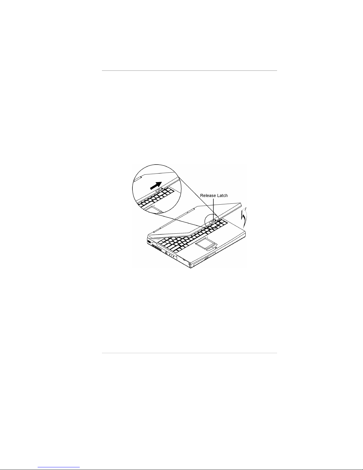
Opening the LCD Panel
At the front of the Notebook you will find a retaining latch on the
display panel which locks the display in closed position when the
Notebook is not in use.
1 Slide the display panel latch to the right until the display panel
releases, and then raise the LCD screen.
2 At any time you can tilt the display toward or away from you to a
comfortable viewing position.
CCaauuttiioonn::
To avoid damage to the display panel:
1. Try not to slam the display upon closing it.
2. Try not to place any object on top when it is closed or open.
3. Be sure the system is turned off or in suspend mode before you
close the display panel.
With the LCD screen open, you will see several features important for
operating your Notebook computer.
Page 22
4
Each of these features is briefly described below.
LCD Cover Release Latch
Slide this latch to the right to open the LCD cover.
Cover Close Switch
When you close the LCD cover, this switch turns off the LCD
backlight.
Stereo Speakers
The internal speakers provide true stereo sound.
SVGA/XGA LCD Screen
Your Notebook computer is equipped with a replaceable color Liquid
Crystal Display (LCD) screen that supports up to 1024 x 768 x 16M
LCD resolution utilizing a AGP BUS. A built-in backlight allows you
to comfortably view the screen even when ambient lighting is low.
Page 23
5
Power/Suspend/Resume Button
Pressing this button when the computer is in Suspend mode will
resume normal operation.
Keyboard
Your computer has an 84-key enhanced keyboard that provides all the
functions of a standard 101/102 key keyboard.
The Built-in Microphone
The built-in microphone is located to the right of the TouchPad.
TouchPad
The TouchPad is hardware-compatible with the IBM PS/2 mouse and
software-compatible with the Microsoft mouse.
TouchPad Buttons
The buttons below the TouchPad correspond to the left and right
buttons on a standard mouse. The PS/2 compatible mouse will work
with the Notebook PC’s TouchPad simultaneously.
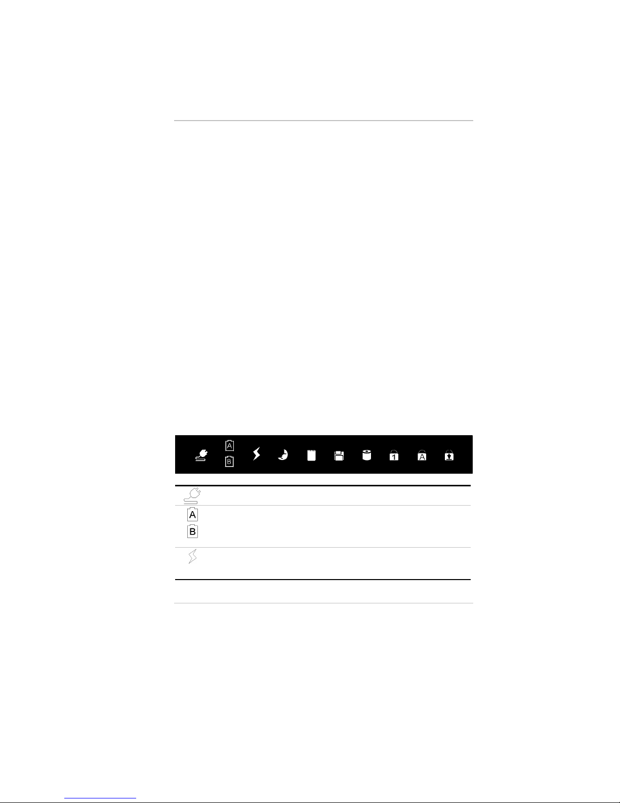
System Status Indicator Panel
The system status indicator panel keeps you informed of the
computer’s operating status.
There are also three system status indicators — Power, Suspend, and
Battery Charge — on the LCD cover.
When lit indicates that the AC adapter is connected.
The A icon indicates that the primary battery is being charged (or
discharged when the AC adapter is not connected).
The B icon has no function in this current version since there is no
secondary battery available.
When Orange indicates that the AC adapter is connected and the
battery is being charged. When the battery is charged to full capacity
the LED is Green.
Page 24
6
Indicates when lit that the Notebook is in Suspend mode. See Chapter
Three for information on Power Management modes.
Appears when the PCMCIA card is inserted to the PCMCIA slot. See
Chapter Three for information on using PCMCIA cards.
Appears when the computer is accessing the FDD drive.
Indicates that the computer is accessing the hard disk drive
Indicates that the keyboard is in Num Lock mode.
Indicates when the keyboard is in Caps Lock mode. In this mode, the
keyboard produces uppercase text when you press a key. When you
press the Caps Lock key again, the indicator goes off and the keyboard
produces lowercase text.
Indicates when the keyboard is in Scroll Lock mode. Some
applications will move information across the screen differently when
Scroll Lock is on.
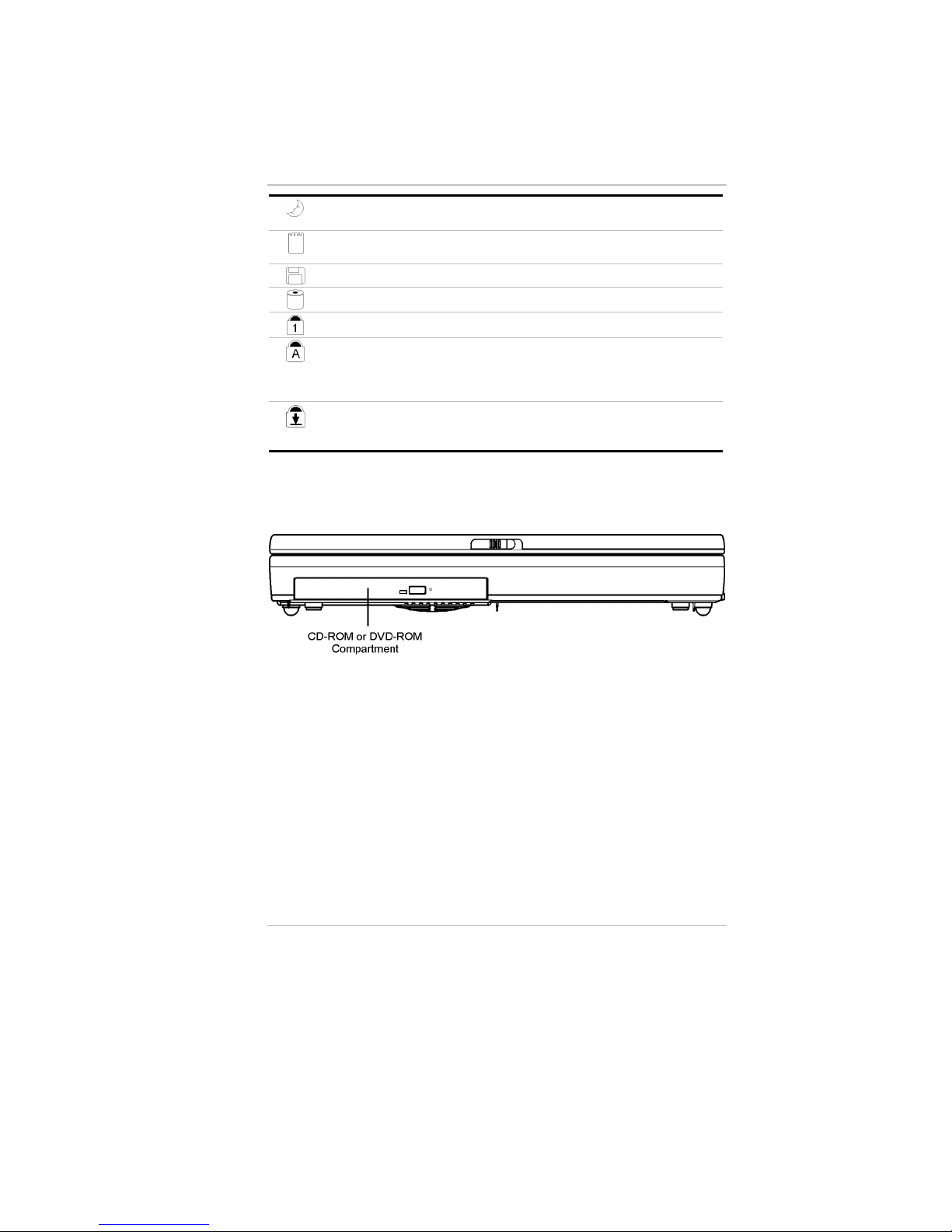
Front Panel
The CD-ROM/DVD-ROM Drive
Your Notebook comes with a swappable 20X (or higher) 5.25" IDE
CD-ROM or DVD-ROM drive.
Page 25
7
Right Panel
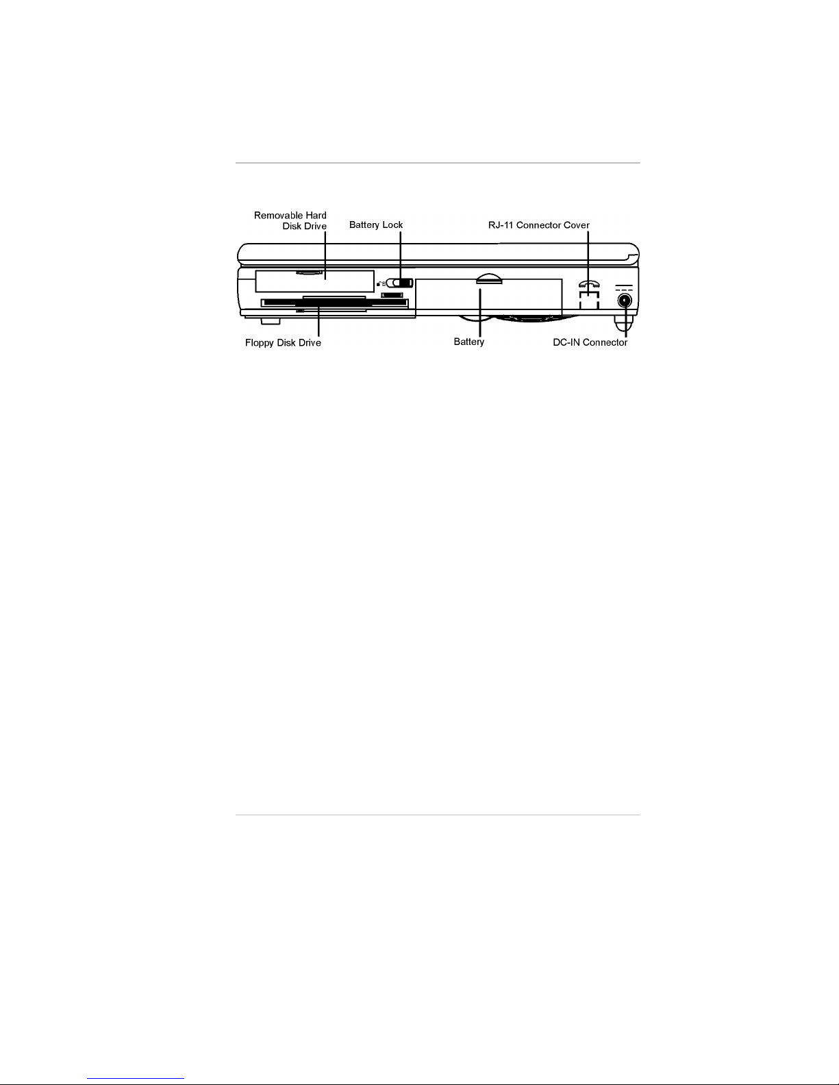
Removable Hard Disk Drive
Your computer includes a removable 2.5-inch IDE hard disk drive
(9.5mm/12.7mm in height) with 1.44GB or more storage capability.
The Notebook PC’s BIOS automatically detects IDE drive types.
The Floppy Disk Drive (FDD)
Your Notebook has a 3.5" floppy disk 1.44MB (FDD) installed.
Battery Lock
Slide the battery lock to the left when removing the battery module
from the battery bay.
Battery
Your Notebook comes equipped with a factory-installed battery pack
module. After the battery runs down, the module can be removed and
replaced with a charged battery.
RJ-11 Connector Cover
If you install an optional internal modem in your Notebook (see
Installing Optional Devices, Chapter Four), this cover must first be
removed to connect an RJ-11 connector to the modem.
The RJ-11 connector cover can easily be levered free with a flattipped screwdriver.
Page 26
8
DC IN Connector
Plug the AC adapter into this connector. Refer to Chapter Two,
Connecting to a Power Source for more information.
Left Panel
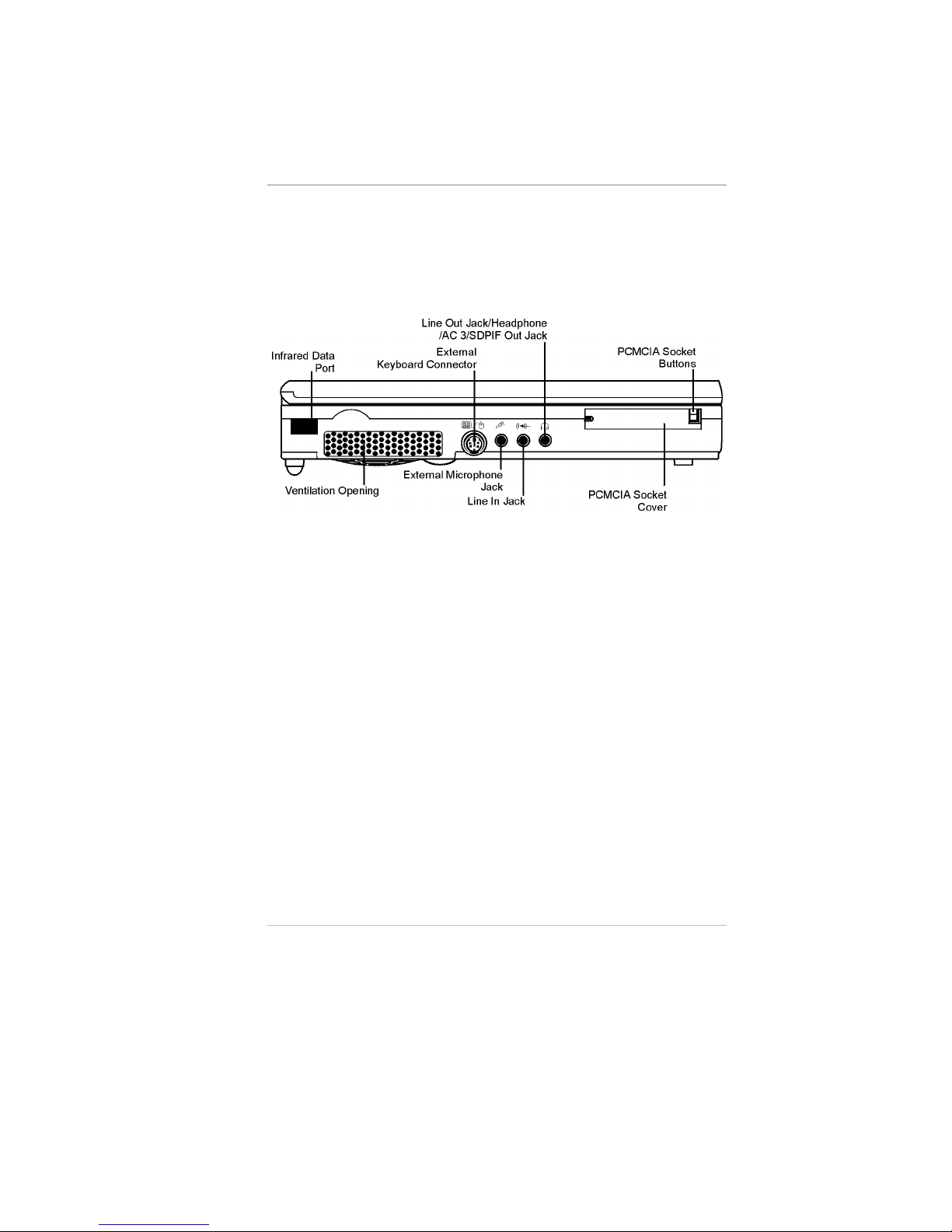
Infrared Data Port
The Infrared Data Port allows your Notebook to become truly
wireless. You can use this port to transfer large amounts of data very
quickly to any other machine (Notebook computers, printers, etc.)
which is also equipped with an IrDA-compliant IR port. This allows
you to print documents without any inconvenient cable hookups.
Ventilation Opening
Please don’t block this opening during operation of the system.
External Keyboard Connector
You can connect an external keyboard, numeric keypad, or IBM PS/2
compatible mouse to this socket, marked with the keyboard/mouse
icon. You can operate both the internal keyboard and an external
keyboard at the same time.
External Microphone Jack
This mono microphone jack is used to connect an external
microphone.
Page 27
9
Headphone/Line-Out//SPDIF Jack
Connect stereo headphones to this jack to listen to the Notebook’s
audio output.
SPDIF engine receives the digital format data, regroup the date to be
synchronous signal and de-multiplexes and audio and other digital
data.
Line In Jack
This jack is for auxiliary input. The auxiliary input can be used to
connect an external audio source (cassette player, CD player, etc.) to
your Notebook.
PCMCIA Sockets Cover
Open this cover to access the PCMCIA sockets. The computer’s
PCMCIA sockets let you extend the capabilities of your computer by
inserting PC cards. The cards are “hot swappable” and change cards
without having to reboot your computer.
PCMCIA Socket Buttons
The computer has two PCMCIA connectors (two PCMCIA type II
connectors or one PCMCIA type III connector). The upper socket is
PCMCIA socket “0”; the lower socket is socket “1”.
Rear Panel
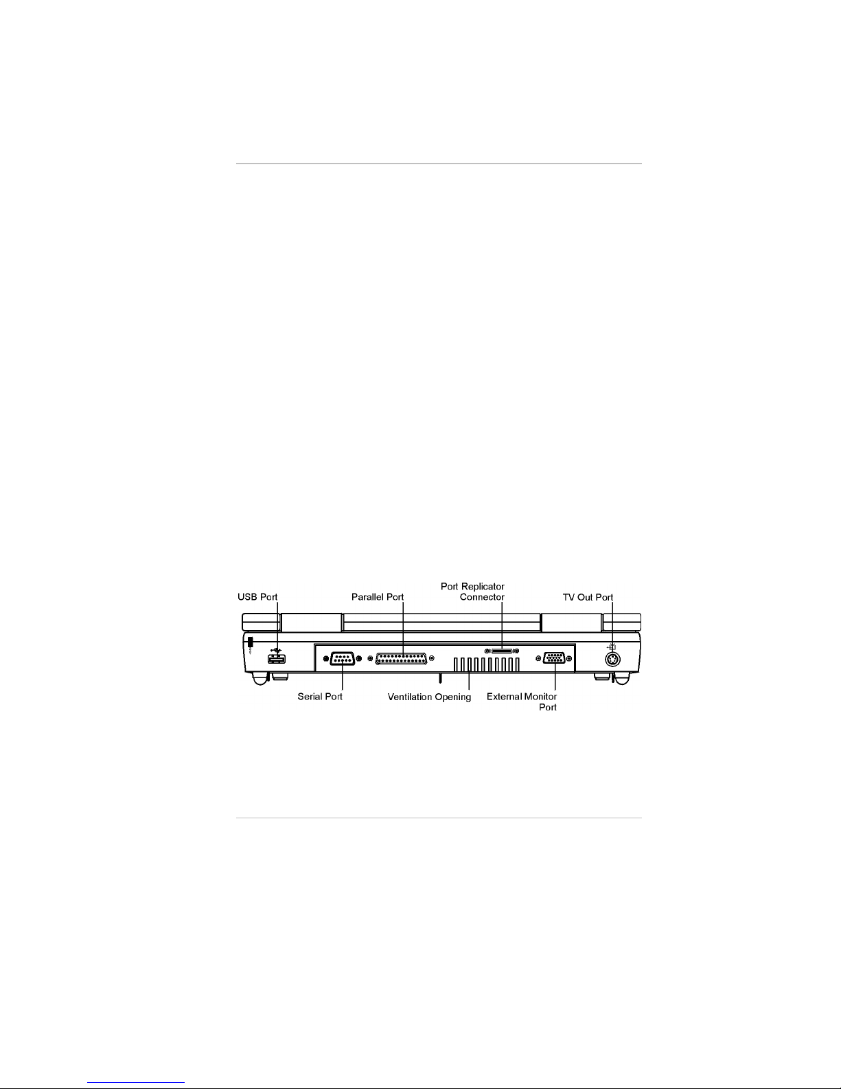
USB Port
Your computer includes one Universal Serial Bus (USB) port. USB is
the latest development in Plug and Play technology.
Page 28

10
It will eventually replace the need for separate connectors for external
keyboards, serial ports, and parallel (printer) ports.
Serial Port
This port is used to connect RS-232 serial devices to the Notebook.
Three types of serial devices are external mice, serial printers, and
fax/modems.
Parallel Port
This port allows you to easily connect a parallel printer or plotter
using this 25-pin bi-directional female port.
Ventilation Opening
Please don’t block these opening when the system is in operation.
Port Replicator Connector
Connect the optional Port Replicator to the 20-pin Port Replicator
connector.
The Port Replicator further enhances your Notebook’s portability by
making it easy for you to connect and disconnect peripheral devices to
your Notebook. Please consult your dealer for details.
External Monitor Port
This port allows you to easily connect an external VGA/SVGA
display monitor into your Notebook using the 15-pin female
connector.
TV Out Port
This 4-pin S-Video port allows you to view the Notebook’s Video
output on a television monitor.
Page 29
11
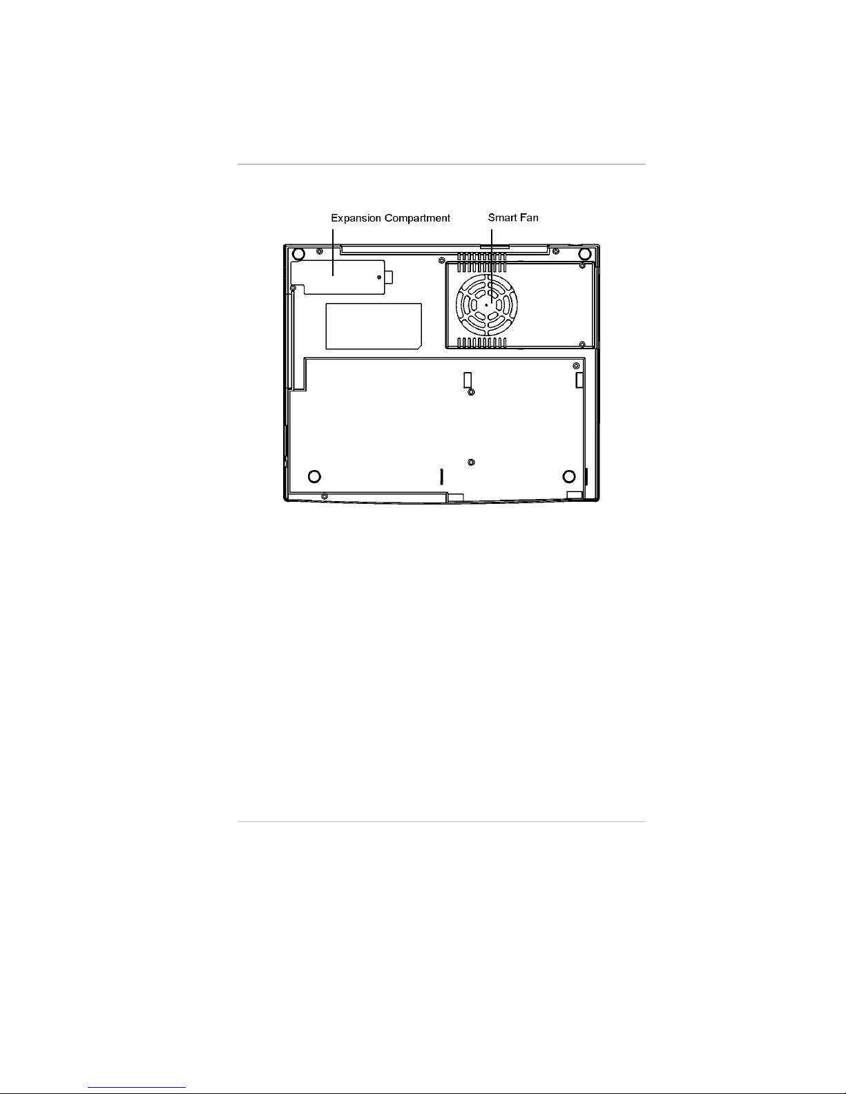
The Bottom Panel
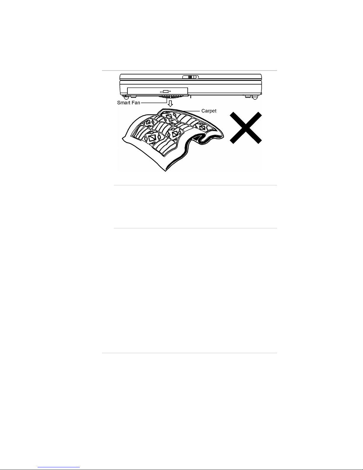
Smart Fan
The Smart fan prevents the Notebook’s CPU and other internal
components from becoming overheated. Keep this fan unobstructed
to allow proper ventilation to the Notebook’s internal components.
There is an automatic thermal sensor that would detect the
temperature of the CPU.
Page 30
12
WWaarrnniinngg::
1. Try not to work on top of a carpet, rug, paper, on the lap or
any material that are easily ignited when the notebook
temperature reaches a certain level.
2. We recommend you to work on top of the table or some other
hard material.
Expansion Compartment
This compartment houses the Internal K56flex Fax/modem MDC
module. For more information refer to Installing Optional Devices in
Chapter Four.
Preparing the Notebook for Transport
To prepare the computer for transport, you should first disconnect all
peripherals. Make sure the computer is turned off before you do this.
After disconnecting all peripherals, close the rear port covers to
protect the connectors. The Notebook’s hard disk head is selfparking. This means that the Notebook can be directly turned off
from the DOS prompt.
Page 31

CChhaapptteer
r
2
2
Getting Started
Operating Environment
To ensure long use and continued high performance, consider the
following factors when setting up your computer:
• Set the computer on a flat, stable surface. To prevent damage,
avoid using the computer where it is expose to strong vibration.
• Place the computer away from electromagnetic or radio frequency
interference.
• Avoid using or storing where it will be exposed to extreme
temperatures. Do not leave the computer in direct sunlight, over a
radiator, or near a heat source for a long period of time. High
temperature can damage the circuitry.
• If you are using the computer with the AC adapter, do not allow
anything to rest on the power cord. Do not place the computer
where people can step on or trip over the cord.
• The openings on the computer are provided to protect the
computer from overheating.
Connecting to a Power Source
Connecting the AC Adapter
A universal AC adapter is provided to supply your computer with
power and also charge the computer’s battery pack. The adapter’s AC
input voltage can range anywhere from 100 to 240 volts, covering the
standard voltages available in almost every country.
Page 32

14
The power cord for the AC adapter requires a two-hole grounded AC
outlet. To connect the computer to an external power source:
1 Plug the AC adapter’s connector into the DC-IN connector on the
right side of the computer.
2 Connect the power cord to the AC adapter and then to a wall
outlet.
CCaauuttiioonn::
The best kind of AC power source to connect your
Notebook to is a UPS (Uninterruptible Power Supply). Lacking this,
use a power strip with a built-in surge protector. Do not use inferior
extension cords as this may result in damage to your Notebook. The
Notebook comes with its own AC adapter. Do not use a different
adapter to power the computer and other electrical devices.
Whenever possible, keep the AC adapter plugged into the Notebook
and an electrical outlet to recharge the battery.
Page 33

15
CCaauuttiioonn::
Never turn off or reset your Notebook while the hard
disk or floppy disk is in use and the FDD and/or HDD status icon is
lit; doing so can result in loss or destruction of your data. Always
wait at least 5 seconds after turning off your Notebook before turning
it back on; turning the power on and off in rapid succession can
damage the Notebook’s electrical circuitry.
Turning On Your Notebook Computer
Turn on your Notebook by pressing the power button. Hold the
button down for a second or two and release. The Power-On Self Test
(POST) runs automatically.
After the POST is completed, the computer reads the operating system
from the hard disk drive into computer memory (this is commonly
referred to as “booting” a computer). If Windows 95 is installed, it
should start automatically.
To turn the Notebook off, save your work and close all open
applications, click on Start, then Shut Down and select Shut down
the computer and click "Yes" or press the power button for 4
seconds.
About the ROM BIOS
Your Notebook computer is configured with a customized Basic
Input/Output System (BIOS), which tests the computer and
determines how the computer reacts to specific instructions that are
part of programs.
About the Power-On Self Test
The Power-On Self Test (POST) runs every time you turn on the
computer. The POST checks memory, the main system board, the
display, the keyboard, the disk drives, and other installed options.
Two kinds of malfunctions can be detected during the POST:
• Error messages that indicate a failure with the hardware, the
software, or the BIOS. These critical malfunctions prevent the
computer from operating at all or could cause incorrect results.
An example of a critical error is a microprocessor malfunction.
Page 34

16
• Messages that furnish important information (such as memory
status) on power-on and boot processes. These non-critical
malfunctions are those that cause incorrect results that may not be
readily apparent. An example of a non-critical error would be a
memory chip failure.
In general, if the POST detects a system board failure (a critical error),
the computer halts and generates a series of beeps.
If failure is detected in an area other than the system board (such as
the display, keyboard, or an adapter card) an error message is
displayed on the screen and testing is stopped.
The POST does not test all areas of the computer, but only those that
allow it to be operational enough to run any diagnostic program. If
your system does not successfully complete the POST, but displays a
blank screen, emits a series of beeps, or displays an error code,
consult your dealer.
Resetting the System
After installing a software application package, you may be prompted
to reset the system to load the changed operating environment. To
reset the system, or “reboot,” press the [Ctrl] + [Alt] + [Delete] keys
simultaneously. This is known as “warm boot.” This key
combination acts as a “software” reset switch when you encounter
hardware or software problems, which lock up the Notebook.
If this key combination does not shut down the Notebook, you can
reset the Notebook by using the Notebook’s power button. Should the
Notebook lock up for some reason, pressing this button powers the
Notebook off.
Adjusting the Brightness
To adjust the brightness on the LCD screen, press and hold down the
[Fn] key in the lower left hand corner of the keyboard and press the
[F7] key to reduce the brightness or [F8] to increase the brightness.
Page 35

17
Operating on Battery Power
Your computer comes with a rechargeable battery pack that lets you
operate the computer without an external power source. When the
battery pack is fully charged, you can operate the computer for
approximately 2 – 2.5 hours for Ni-MH battery and 2.5 – 3.5 hours for
Li-Ion battery under the following conditions:
• The battery pack initially has a full charge.
• No peripheral devices are installed.
• The disk/CD-ROM drives run no more than 10% of the time.
NNoottee::
Only use batteries that are approved by an authorized
dealer. All batteries are not the same and therefore should not be
treated as such. Using the wrong battery could cause serious
damage to your computer and yourself through toxic emissions.
Inserting and Removing the Battery Pack
The battery pack should already be inserted in your Notebook
computer when you unpack it. If not inserted, follow these directions:
1 Turn off the Notebook and open the battery bay door. Slide the
battery release latch to the left.
2 Insert the battery and slide the battery release latch to the right and
close the battery compartment cover.
To remove the battery pack:
1 Turn off the computer and open the battery bay door.
2 Slide the battery release latch to the left.
3 Lift the battery finger grip and pull the battery from the bay.
Page 36

18
Charging the Battery Pack
The installed battery pack charges automatically any time the
computer is connected to the AC adapter and an external power
source. The Ni-MH battery pack can be fully charged in about 2.5
hours when the computer is turned off or over four hour when the
computer is on. The Li-Ion battery can be fully charged in about 4
hours when the computer is turned off.
NNoottee::
It is a good idea to occasionally discharge the battery pack
fully to preserve its operating performance. For details, see
“Batteries & Battery Discharge” in Chapter Eight.
Page 37

19
A Word about Ergonomics
Ergonomics is the study of how people with their different physical
characteristics and ways of functioning relate to their working
environment (the furnishings and machines they use).
The goal of Ergonomics is to incorporate comfort, efficiency, and
safety into the design of keyboards, computer desks, chairs, and other
items in an effort to prevent physical discomfort and health problems
in the working environment.
Following are a few tips to help you work effectively without a lot of
physical discomfort:
• Purchase a chair with armrests and good back support. Don’t
slouch when sitting; keep your back straight.
• Place the LCD panel or external monitor so that it is a little above
eye level — when using a word processor remember to Scroll
Down often to ensure you are reading or typing at the top of the
screen; this will help to prevent neck strain:
• Try to place the LCD panel or external monitor so that there is
little glare from the sun on the monitor.
• Walk around the room every hour.
• Every half-hour look away from the computer screen for a few
minutes.
• Place everything that you need to work within easy reach.
Page 38

20
This page is intentionally left blank
Page 39

CChhaapptteer
r
3
3
Using the Notebook
Computer
The LCD Display
The Notebook comes with a Color LCD display panel that supports
the following display options:
Display Resolution Color Depth
12.1” DSTN/TFT SVGA 800 x 600 256 Color
14.1” TFT XGA 1024 x 768 256 Color
All displays support up to 1024 x 768 x 64K color mode on an
external CRT. The LCD screen display results can be adjusted by
changing the LCD panel angle, and the display brightness.
Adjusting the LCD Screen Display
The LCD screen display can be adjusted by the following key
combinations.
Key Combinations Definitions
[Fn] + [F5] Decreases the contrast level of the display
(for DSTN display only)
[Fn] + [F6] Increases the contrast level of the display
(for DSTN display only)
[Fn] + [F7] Decreases the brightness level.
[Fn] + [F8] Increases the brightness level.
[Fn] + [F12] Switches between LCD and CRT displays.
Page 40

22
LCD Care
LCD screens are delicate devices that need careful handling. Please
pay attention to the following precautions:
• When you are not using the computer, keep the LCD screen
closed to protect it from dust.
• If you need to clean your LCD screen, use a soft tissue to gently
wipe the LCD surface.
• Do not put your fingers or sharp objects directly on the surface
and never spray cleaner directly onto the display.
• Do not press on, or store any objects on the cover when it is
closed. Doing so may cause the LCD to break.
External CRT Display
You can hook up an external monitor through the 15-pin CRT
connector. Three configurations are available:
• LCD only
• Simultaneous display of the LCD screen and CRT monitor
• CRT only
You can switch between these display configurations by pressing the
key combination [Fn] + [F12]. For information on connecting an
external display, please refer to Chapter Four.
A Tour of the Notebook’s Keyboard
The Notebook’s keyboard uses a standard QWERTY layout with the
addition of special function keys and an embedded numeric keypad
for number intensive data entry. Your keyboard supports Windows 98
by incorporating the two Windows specific keys. With the two
Windows 98 keys you will be able to access and take advantage of
many of the time-saving features of Windows 98 software.
The QWERTY layout means the alphanumeric keys located on the
keyboard are in the same position as those found on a standard
typewriter.
Page 41

23
[Esc]: The Escape key allows you to cancel any specific command
you may have just keyed in.
[PrtSc/SysRq]: Pressing this key will cause whatever is on the
screen at the time to be printed. Consult your software user’s
manual for more information. To use SysRq, press the [Fn] key and
the [PrtSc/SysRq] key together.
[Scroll Lock]: When Scroll Lock is engaged, pressing the cursor
control keys moves the cursor by fields of text. Press the scroll lock
key once to engage this mode. Pressing it a second time will
disengage the Scroll Lock function.
[Pause/Break]: The Break key is used in conjunction with the
Control key ([Ctrl] + [Break]) to cancel a command.
[Alt]: Used by itself, the Alternate Key has no effect in carrying out
any commands, but functions with the [Ctrl] and [Del] key ([Alt] +
[Ctrl] + [Del]) to reboot or restart your operating system program.
[Caps Lock]: The [Caps Lock] key corresponds to a typewriter’s
Shift Lock key, but it only affects letter keys. The number keys and
function keys are not affected. Note that when the [Caps Lock] key
is engaged, the Caps Lock Status symbol comes on in the System
Window display.
[Shift]: Similar to the typewriter’s Shift key, this key allows you to
type letters in “UPPER CASE.”
[Ctrl]: Used by itself, the Control key has no effect in carrying out
any commands. Its function depends mainly upon the type of
software you are currently using.
Windows 95/98 Keys
There are two specials Windows 95/98 keys on the keyboard. A
brief description of each key is given below.
Page 42

24
The key with the Window 95/98 Logo activates the Start menu
button on the bottom left of the screen.
This key activates the properties menu and is equivalent to pressing
the left mouse button.
The Notebook’s Hot Key Controls
Key Combinations Definitions
[Fn] + [F1]
This key combination enables/disables the
mute the PC beep sound.
[Fn] + [F3] + [F4] This key combination turns off the volume.
[Fn] + [F3] Increases the speaker volume.
[Fn] + [F4] Decreases the speaker volume.
[Fn] + [F5]
Decreases the contrast level of the display
(For DSTN only).
[Fn] + [F6] Increases the contrast level of the display
(For DSTN only).
[Fn] + [F7] Decreases the brightness level.
[Fn] + [F8] Increases the brightness level.
[Fn] + [F9]
This key combination toggles the display
between the LCD display and an external TV.
[Fn] + [F10] Pressing the key combination switches the
display 640 x 480 and 800 x 600. The display
must be set to 640 x 480 in the control panel
beforehand.
[Fn] + [F12] Switches between LCD and CRT displays.
[Ctrl] + [Pause Break] Halts the current operation
[Ctrl] + [C] Halts the current operation without clearing
the keyboard buffer
[Ctrl] + [Alt] + [Del]
This is the warm boot key combination used
to reset the computer.
Page 43

25
The Function Keys
Notice the twelve function keys in the top row of the keyboard. These
keys appear in sequence ([F1], [F2], [F3], . . . & [F12]) from left to
right. The functions of these keys vary with respect to the operating
system and software in use.
The Cursor Keys
The four direction (arrow) keys control
the movement of the cursor on the
screen. They do not affect the displayed
characters.
Embedded Numeric Keypad
The embedded numeric keypad consists of 15 keys that make number
intensive input more convenient. Like the [Num Lock] key, these
keys are labeled in blue on the keycaps. Numeric assignments are
located at the upper right of each key.
When the numeric keypad is engaged, the
NumLock icon will appear in the System
Window. The keypad is activated by
pressing the [Fn] + [NumLk] key. If an
external keyboard is connected, pressing
the NumLock key on either the Notebook
or external keyboard will enable/disable
NumLock of both keyboards in unison.
To disable the Notebook numeric keypad while keeping the keypad on
an external keyboard activated, use the [Fn] + [NumLk] hot key on the
Notebook keyboard.
Page 44

26
The TouchPad
Using the TouchPad
The TouchPad is a pressure sensitive pointing device that provides all
the features of a two-button mouse.
1 The TouchPad is easily accessible by moving either your left or
right thumb off the space bar and on to the TouchPad.
2 Gently move your thumb across the pressure-sensitive TouchPad
in the direction you want the cursor to move.
3 The TouchPad offers a method of making selections called
double-tapping and this corresponds to double-clicking with a
mouse.
4 Clicking the buttons below the TouchPad makes selections, drags
objects, or performs a variety of other functions depending on the
software.
Page 45

27
TouchPad Precautions
The TouchPad is a pressure sensitive device. Please take note of the
following precautions.
• Make sure the TouchPad does not come into contact with dirt,
liquids or grease.
• Do not touch the TouchPad if your fingers are dirty.
• Do not rest heavy objects on the TouchPad or the TouchPad buttons.
You can use the TouchPad with Microsoft Windows as well as nonWindows applications.
Connecting an External Tracking Devices
The system will only enables you to use one tracking device whether
it is an internal or external tracking device.
Connecting an External PS/2 Device or Microsoft’s
IntelliMouse
When an external PS/2 device or Microsoft’s IntelliMouse is
connected to your system, the touchpad will be automatically
disabled.
Data Storage and Retrieval
Data storage and retrieval are two of the most fundamental tasks you
will perform when working with your computer. The Notebook is
equipped with a 3.5" floppy disk drive (FDD) and a hard disk drive
(HDD). The HDD is removable allowing for easy upgrades.
These two types of drives and their associated circuitry comprise your
computer’s main data storage and retrieval system. The following
sections will cover instructions for operating each of these drives.
The Floppy Disk Drive
Your Notebook features a removable high-density 3.5-inch floppy
disk drive module. It is designated drive A by the operating system.
Page 46

28
Caring for Disks
Under normal conditions a diskette’s rigid plastic case will protect it
from damage. However, data stored on floppy diskettes are easily
corrupted.
• Never touch the magnetic surface of the disk. When handling
diskettes, take care that you don’t drop them. Keep diskettes
away from liquids.
• Never turn off, reboot, or reset the computer when a diskette is in
the drive and the drive activity light is on. Do not transport the
computer with diskettes inserted in the drive.
• Do not expose diskettes to extreme temperatures or high
humidity.
• Keep diskettes away from magnetic fields generated by power
supplies, monitors, magnets, etc.
• Don’t smoke in the same room where diskettes are used or stored.
Particles from cigarette smoke are large enough to scratch the
surface of the disk. Store diskettes in a dry, dust-free
environment.
CCaauuttiioonn::
Never turn off or reset the Notebook while the LED is
on. Always try to store your diskettes in a dry, clean container, to
protect them from the environment and magnetic fields.
The Removable HDD Module
Your computer’s hard disk drive is an integrated electronic drive,
commonly referred to as an IDE drive, with a form factor of 2.5
inches. The formatted capacity of the Notebook’s HDD is 2.1GB or
above.
Removing and Replacing the Hard Disk Drive
The Notebook’s hard disk is easily removed and replaced to allow
easy upgrades. To remove the hard disk drive:
1 Open the HDD cover and slide the latches to release the HDD.
2 Gently pull on the HDD cover and slide the HDD out of its bay.
Page 47

29
3 To reinsert the HDD module, simply slide the HDD into its bay
until it mates with its connector.
4 Lock the HDD module by sliding the latches in the opposite
direction just as when you are releasing the HDD mentioned in
Step 2. Close the HDD cover.
The CD-ROM
Features of the CD-ROM Module
The features of the CD-ROM drive are listed below.
• The Audio Play feature allows you to play music CDs
• Front panel load/unload button
Page 48

30
• Supports CD-DA, CD-ROM mode 1 and mode 2, Multi-Session
Photo CD™, CD-I/Video CD (pcs.)
• Low power consumption
• 12.7mm height
Precautions for Handling CD-ROM Discs
• Always hold the disc by the edges, avoid touching the surface.
• Use a clean, dry, cloth to remove dust, smudges, or fingerprints.
Wipe from the center outward.
• Do not write or place objects on the surface of the disc.
• Store discs in a cool dry place not to damage the disc.
• Do not use benzene, thinners, or cleaners with detergent. Only
use CD-ROM cleaning kits.
• Do not bend or drop the discs.
Loading a Disc
To play a CD disc, follow the instructions listed below.
1 Push the CD-ROM eject button on the CD drive door. Gently
pull the tray all the way out.
2 Carefully lift the CD-ROM by the edges and make sure the shiny
surface is face down (the side with no writing on it). Carefully
insert the CD-ROM onto the tray. Push the CD-ROM down
gently so that it snaps onto the center ring.
3 Push the tray back into the drive.
To remove a CD-ROM, do the following:
1 Check the LED display and make sure that the computer is not
accessing the CD-ROM drive.
2 Push the eject button and pull the tray all the way out.
3 Carefully pick up the CD by the edges and – while pressing down
on the center ring – remove the CD-ROM from the tray.
Page 49

31
NNoottee::
Do not insert any foreign objects into the disc tray. If you
experience difficulty when ejecting the CD disk tray, stretch a paper
clip (or use a pin or a thin metal rod) and insert it into the emergency
eject hole located on the right side of the front panel. The CD disk
tray should eject immediately. This procedure can also be used to
remove a CD from the drive when the Notebook is powered off.
The Multimedia Sound System
The Notebook’s built-in audio capabilities allow you to take
advantage of a wide range of education and entertainment multimedia
software. The Notebook is equipped with two internal stereo
speakers, a microphone, and input audio ports for external audio units.
An external microphone can be connected to the microphone jack.
External speakers or headphones can be connected to the Notebook’s
audio-out jack.
External audio devices can be connected to the Line in jack. All audio
features are software controlled. The Notebook’s multimedia sound
system includes the following features:
• A Creative chipset
• Supports Windows Sound System compatibility
• Full Duplex operation
• Dynamic filtering reduces noise and distortion rate
• 16-bit digitized audio playback
• A built-in microphone for convenient recording
• Two built-in stereo speakers
• Digitized audio recording through the Notebook’s built-in
microphone or any external source
Audio Volume Control
The Notebook is equipped with hot-key volume controls: Pressing the
[Fn] + [F3] hot-key combination decreases the audio output volume,
press the [Fn] + [F4] hot-key combination to increase the volume.
Page 50

32
IR Communication
At the left side of the Notebook is the Infrared (IR) communication
module that consists of one Light Emitting Diode (LED) and one
photo sensor.
Its function is to act as a transmitter and the photo sensor acts as a
receiver. The IR module enables you to perform wireless, serial
communication. Use an FIR-specified application to transmit or
receive data via the Notebook’s FIR module.
The following table briefly describes each of the IR modes available.
You must set these modes in BIOS. Please refer to Chapter Five for
information on the BIOS Setup program.
IR Type Description
FIR Fast Infrared.
IrDA Infrared Data Association protocol
Follow the guidelines listed below when using the Infrared
Communication module to transmit or receive data.
• Make sure the Infrared Communication field in the BIOS Setup
program is set to FIR.
• Ensure that the Notebook’s FIR module is properly lined up with
the other device’s Infrared Communication module with an angle
not exceeding ±15°.
• There should be a clear, unobstructed path between the two
Infrared Communication modules; otherwise the optical signal
will be blocked.
• Do not move either the Notebook or the other device during
transmission of data; otherwise data transmission will be distorted
resulting in loss of data or a system crash.
• An error can occur if FIR transmission is conducted in an
environment with high levels of noise.
Page 51

33
PCMCIA Cards and Expansion Sockets
The Notebook features two PCMCIA expansion sockets designed to
interface with one or two Type II cards or stacked to accommodate
one Type III card.
Inserting a PCMCIA Card
The computer will emit a medium tone followed by a high tone when
a PC card is inserted. When you eject a card, the computer will emit a
high tone followed by a medium tone. You can insert and remove a
PC card whether the computer is turned On or Off.
Follow these instructions to insert a PCMCIA card:
1 Hold the PCMCIA card with the arrow side up and the connector
side toward the socket.
2 Align the card connectors with the appropriate socket and
carefully slide into the socket until it locks into place. The
system will beep once to indicate that it has detected the PC card.
To remove a PC card push the respective eject button, the button will
pop out, push the button again to eject the PCMCIA.
The upper button will eject a Type II PCMCIA card while the lower
button will eject a Type II or Type III PCMCIA card from the lower
socket. Then remove the card and store it properly.
Page 52

34
NNoottee::
When inserting a Type III PC card, make sure the connector
is inserted in the lower socket. Before ejecting a PC card, ensure
that it is not being accessed by the System.
For example, if the message “Write protect error writing Drive x” is
displayed, the user has to change the write protect switch setting on
the memory card. To change the switch setting, (a) eject the card,
(b) change the switch setting, and (c) re-insert the card.
Power Saving Modes
This section contains information on the Notebook’s power system,
including the AC Adapter, the battery system, recharging the battery,
and tips for conserving battery power. The power system is
comprised of two parts, the AC Adapter and the battery system. The
AC Adapter converts AC power from a wall outlet to the DC power
required by the computer.
The AC Adapter
The AC Adapter’s primary function is to provide power to the
Notebook. If the AC Adapter is not functioning properly, please
consult your dealer immediately for support.
Page 53

35
The Battery Power System
A fully charged pack will provide approximately 1.6 to 2.0 hours of
battery life. The battery life can be extended by using the power
management features.
Before using the computer on battery power for the first time, check
the battery status icon on the Windows Toolbar to make sure the
battery is fully charged. See Battery Status later in this section for a
description and explanation of the Windows Battery icon.
Charging the battery takes about 2.5 hours for the Ni-MH battery
pack. The Li-Ion battery pack takes about 4 hours to charge when the
system is in off state. If possible, always charge the battery
completely.
Removing the Battery Pack
To remove the battery pack from its compartment, please refer to
Chapter Two, Inserting and Removing the Battery Pack.
Preparing the Battery Pack for Use
Before using the battery pack for the first time, the Smart Battery IC
within the battery pack should be calibrated in order to get accurate
reporting of remaining battery life status. To calibrate the battery
pack follows the instructions below:
1 Insert the battery into the battery compartment and turn on the
Notebook. If the battery is completely without power go to the
next step. Otherwise, let the battery run down until the battery
low-low warning beeps are heard. The system will automatically
enter Suspend mode.
2 Turn the Notebook off. Connect the AC adapter and let the
battery fully recharge. When the battery charge indicator turns
off, the battery is fully charged.
3 The battery pack is now calibrated properly.
Page 54

36
In general, using the battery until the low-low battery-warning
indicator appears and fully recharges the battery each time (full
discharge/charge cycle) will ensure the accurate reporting of the
battery gauge status.
Automatic Battery Pack Charging Function
You can automatically charge the battery pack by using the AC
Adapter. The charge time is about two and a half-hours (Ni-MH) or
four hours (Li-Ion) when the Notebook power is turned off. The
following table summarizes the charging modes:
Charge Mode Charge Time
Fast
• Ni-MH Battery Pack
2.5 hours with the system off or in
Suspend mode.
• Li-Ion Battery Pack
4 hours with the system off or in
Suspend mode.
Trickle
(Ni-MH battery pack
only)
When the system is on or off, a trickle
charge is supplied to the Ni-MH battery pack
to maintain full charge capacity after being
charged.
Pre-Charge
(Li-Ion battery pack only)
A pre-charge is supplied to the Li-Ion
battery pack.
NNoottee::
If the temperature of the Ni-MH battery rises, we would
temporarily close down the battery charging function in order to
extend the battery life. The charging process would continue if the
temperature drop to a certain level. If you prefer to cut short the
charging time, we would recommend you to turn off the power of
the system.
As for Li-Ion battery, there is no limitation since the temperature
will not rise during the charging process.
Page 55

37
Battery Status
Windows 95 and Windows 98 has an applet in the Control Panel that
will display an icon in the Windows taskbar indicating when the
Notebook is running on battery power or is attached to the AC
adapter. This applet also displays a meter that indicates how much
charge is remaining in the battery.
For Windows 95
To open this program click on
Start, then Settings. Click the
Control Panel icon.
In the Control Panel, double
click the Power icon. The
screen will display the
illustration shown below:
Click the box next to Show battery meter on the taskbar to have the
power icons displayed on the Windows taskbar.
When the AC plug is displayed, it indicates that the
AC adapter is attached to the Notebook.
When the battery icon is displayed, it indicates that
the Notebook is running on battery power.
Double click the battery icon to display the following screen:
Page 56

38
This screen indicates how much battery charge remains.
For Windows 98
In the “Control Panel”,
double click the “Power
Management” icon to display
the “Power Management
Properties” as shown on the
right screen.
Power Scheme
In setting your power options,
click on the “Power Scheme”
tab to select the power scheme
most appropriate for you in
using your computer.
• Home/Office Desk
• Portable/Laptop
• Always On
Settings for Portable/Laptop power scheme
Under this item you are allowed to set the time setting for the system
to enter the standby mode whether you are operating the system by
battery or AC power source.
Page 57

39
Turn off monitor
Under this item, you are allowed to set the time
setting to turn off the monitor whether you are
operating the system by battery or AC power source.
Turn off hard disks
Under this item, you are also allowed to set the time
setting to turn off the hard disks either operated by
battery or AC power source.
Power Meter
Click on the “Power Meter” tab to display the type of power source
you are using to operate your notebook computer.
This indicates the Notebook is
operated with battery.
This indicates the Notebook is
operated with an AC power source.
If the battery charge drops below a certain voltage level, a beeping
sound will prompt you to save your work and turn off the computer,
or connect the AC adapter. The message is:
You should change your battery or switch to outlet power
immediately to keep from losing your work.
Battery Low Warning
When the pack initially reaches the “Battery Low” state
approximately 10 ~ 15 minutes of the usable battery life is left.
You will hear an audible beep signal every 1.5 seconds alerting you to
the “Battery Low” status. When the battery power reaches the
“Battery Low Low” status the beeping sound will accelerate.
Your battery now has 1 ~ 2 minutes of battery charge remaining. You
must save your data or connect AC power immediately; otherwise,
you may lose your data.
Page 58

40
NNoottee::
The Notebook can not be powered on while the battery is in
the “Battery Low” state: to power the Notebook on once the battery
pack has reached the “Battery Low” state, the AC adapter must be
connected.
Sound Meaning
Continuous beeping
every 1.5 seconds
Battery Low: Indicates that there is 10 to 15
minutes charge remaining.
Beeping accelerates Battery Low Low: Indicates that there is 1 to 2
minutes of battery charge remaining. Save your
work and turn off the Notebook, or connect the
AC adapter.
When there is only one minute of battery charge remaining, the
Notebook will suspend to the HDD (if a PHDISK HDD partition has
been set) and power off. If a PHDISK HDD partition has not been set
the Notebook will suspend to DRAM. You should connect AC power
and resume to save your work.
Windows 95 OSR/2 has a Smart Battery function that allows you to
change the settings for the battery warning signals. Please consult the
Windows 95 OSR/2 help for details.
To extend battery power, we recommend that you make full use of the
Notebook’s built-in power saving features.
Small Battery for the Real Time Clock
There is a small built-in battery pack that supplies power to the system
in order to maintain certain system information while the power is off.
If the Notebook is left without a power source for too long, this
battery will be exhausted and system information will be lost.
WWaarrnniinngg::
Never remove the battery pack while the power is on as
this may result in data loss when the system loses power.
Page 59

41
Power Management Modes
The computer has a number of automatic or adjustable power saving
features which you can use to maximize battery life. You can control
some of these features through the Power menu in the Setup program.
The computer is made up of electronic components, all of which
consume electricity to operate. Yet, some components consume much
more than others. The power management features are designed to
save as much electricity as possible by putting these components into
a low power consumption mode as often as possible.
These low power modes are referred to as “Standby” mode and
“Suspend” mode. Standby mode is also commonly known as System
Sleep mode.
Full Power Mode
The computer operates in Full Power mode when power management
is disabled. When the computer is operating in Full Power Mode, the
Power LED remains on.
Standby Mode
In addition to reducing the CPU speed, this mode puts peripheral
components in their lowest active states. These peripheral
components include the hard disk, the LCD screen and the screen
backlight.
The Notebook enters Standby mode when the system remains idle for
a specified amount of time. Press any key to resume system
operation.
Suspend Mode
In Suspend mode the CPU clock is turn off and most of the
computer’s peripheral components are put in their lowest active states.
These include the hard disk and the LCD display. The computer
enters Suspend when the system remains idle for a specified amount
of time. Press the Power button to resume system operation.
Page 60

42
A Suspend Example
The time out settings for Hard Disk Off, System Standby, and System
Suspend specify the amount of time the system must be inactive
before the next power management level is enabled. Refer to Chapter
Five, The Power Menu. The example below demonstrates this
function.
If the Hard Disk Timeout is set to 2 minutes, the Standby Timeout to 8
minutes and Auto Suspend Timeout is set to 10 minutes the following
power management events take place:
1. After 2 minutes of system inactivity the hard disk spins down.
2. After 6 additional minutes (a total of 8 minutes of inactivity) the
system enters Standby.
3. After 10 additional minutes in the system Standby mode, the
system suspends to memory or disk.
After the system has suspended, operation can be returned (resumed)
to the point in your application where it was suspended.
How to Suspend
The system can be suspended in the following ways:
• System enters Auto Suspend. This is enabled by setting a time
out period for the Auto Suspend field in the Power menu.
This time out period is the amount of idle time that the system
allows before a Suspend is initiated.
• System suspends to hard disk when battery level is critically low.
A PHDISK partition must be created on your hard drive to enable
this feature. Refer to Chapter Seven for details.
• Pressing and holding the power button for 1 second.
Page 61

43
WWaarrnniinngg::
POWER.EXE must be loaded in a DEVICE =
line in your CONFIG.SYS for APM (Advanced Power Management)
to work correctly while under DOS or Windows 3.x. Failure to use
POWER.EXE could cause the Notebook to become unstable or crash
during SUSPEND/RESUME operations. POWER.EXE is not
necessary while running Windows 95. For additional information
refer to your DOS User’s Manual.
How to Resume
Pressing the power button causes the system to resume operation after
entering the Suspend mode. Resuming returns the system’s operation
to the point in your application where the suspend mode was initiated.
This does not mean, however, that all devices are powered up. When
the system resumes, the following events occur:
• DRAM refresh memory returns the system to the application that
was running before the Suspend operation
• The video is turned on.
• The COM ports are enabled.
• Then, each device is powered on when it is requested for use by
the system.
Power Management Summary
Power Mode How to Enter Mode How to Reactivate
System Idle
• Transits automatically • Press any key,
• Access HDD
System Standby
• Transits automatically
after specified time out
• Press any key
System Suspend
(Suspend to Disk or
Suspend to RAM )
• Transits automatically
after specified time out.
• Press Power button.
• Battery low state.
• Press the Power
button
Hard Disk spin down
• Transits automatically
after specified time out
• Access HDD
Page 62

44
The APM Interface
In addition to the power saving features built into the resident BIOS
System Configuration Utility, your Notebook computer also supports
the Intel-Microsoft Advanced Power Management.
APM is a cooperative interface that enhances the Notebook’s built-in
power management features by providing one of the most accurate
schemes for detecting true idle. This allows APM implementation to
put the CPU in a lower power state with no loss in user performance.
If APM is installed and properly configured, and power management
is enabled in the Setup program, APM functions in the following
manner:
• Takes over power management from system BIOS
• Constantly monitors all system activity to provide one of the most
accurate detection schemes for determining true idle under DOS,
Windows, and OS/2
• Accounts for operating system inactivity and power demands
• Accounts for application inactivity and power demands
• Allows application programs, DOS, and BIOS to share power
management features to ensure more efficient use of power
• Determines when power-saving features should be activated
• Operates transparent to the user (behind the scenes)
While you are running an APM aware application, APM will detect
any system inactivity. If APM detects that either the operating system
or the application is waiting for input (or is in some other idle state);
APM will reduce the CPU to minimum speed. Once high speed is
required again, APM will increase the CPU to maximum speed. With
APM constantly monitoring all system activity, accounting for the
Notebook’s power consumption, and controlling all power-saving
features, you will realize significant additional power savings.
Page 63

CChhaapptteer
r
4
4
Connecting Peripheral
Devices
External Keyboard/Numeric Keypad
You can use your Notebook computer with an optional external
keyboard, numeric keypad, or IBM PS/2 compatible mouse. The
devices are “hot pluggable”. You do not have to power down the
Notebook to connect these devices.
1 Plug the keyboard cable connector into the PS/2 keyboard socket
on the left side of the computer.
To connect a PS/2 compatible mouse to your computer:
1 Plug the PS/2 mini-din connector into the keyboard/mouse socket
on the left of the computer.
Page 64

46
2 The mouse works immediately after being plugged in.
External Monitor
You can use an optional external VGA/SVGA display monitor with
your computer.
1 Plug the monitor’s signal connector into the external monitor
port. Secure the screws on the connector.
2 Plug the monitor’s power cable into a wall outlet.
3 Before you turn on the monitor, turn on your computer and use
the System Setup to designate the screen(s) that you want to use.
Parallel Printer
Your Notebook computer is equipped with an enhanced bi-directional
parallel port. Use the parallel port to connect the computer to a printer
or plotter.
Page 65

47
Serial Devices
The RS-232C serial interface port is used to connect a peripheral
device that can both input data to the computer and receive data from
the computer. The serial port is designated as COMA. After you
connect a peripheral device to the serial port, secure the two small
screws on the connector.
Page 66

48
NNoottee::
You cannot use the TouchPad with a serial mouse at the
same time. When the serial mouse is connected to your Notebook,
the TouchPad will be automatically disabled.
Audio Sources and Output Devices
The built-in audio let you record and play back sound from a variety
of sources. These features include:
• Scalable sampling rate (from 4 to 48 kHz) and compression ratios
that gives complete control of record time to required storage
ratio.
• 3-D positional audio DirectX™ 5.0
• Digitally controlled volume with muting.
• Auxiliary line-in and speaker line-out for maximum flexibility.
• Built-in microphone and speaker to enhance portability.
To adjust the volume of your internal speakers or speakers attached to
the stereo speaker port, use the volume controls found in your
application or in the Windows Volume Control accessory.
Your computer comes with several software utilities and programs
already installed. Among these is a group of programs that let you
control the computer’s various audio capabilities.
Page 67

49
Port Replicator
You may optionally purchase a port replicator for your Notebook
computer. Rather than having to detach all your devices every time
you take your Notebook computer with you, and then reattach them
when you come back, all the devices connect to the port replicator,
which you then connect to your computer through a single port.
USB Device
You may optionally purchase a USB (Universal Serial Bus) for your
Notebook computer. USB devices such as mice, keyboards, and
monitors are becoming more widespread throughout the Computer
Industry. The USB bus has a total bandwidth of 1.5MB per second.
Up to 127 devices can be attached in a daisy chain fashion. It is
expected to be used for devices such as the mouse, keyboard, printer
and scanner.
TV Out
You can connect a TV monitor to the Notebook’s S-Video port and
view the Notebook’s video output.
Page 68

50
The TV Out port accommodates a Mini DIN type connector.
Installing Optional Devices
The K56flex Fax/modem MDC module can be installed in the
expansion card bay of the Notebook.
1 Remove the Phillips screw from the expansion bay cover (1) and
lift the cover free (2). Position the expansion card so the
expansion card connector is facing down.
Page 69

51
2 Insert the expansion card under the Notebook casing (3) and then
push down on the card so its connector mates with the mainboard
connector (4).
3 Replace the expansion bay cover and secure it with the screw you
removed at Step 1.
NNoottee::
Before installing the Fax/Modem card you must first
remove the RJ-11 connector cover, from the right side of the
Notebook.
Page 70

52
This page is intentionally left blank
Page 71

CChhaapptteer
r
5
5
Running BIOS Setup
Introduction
The BIOS (Basic Input and Output System) Setup program is a menu
driven utility that enables you to make changes to the system
configuration and tailor your system to reflect installed hardware or
alter system performance. When the Notebook is turned back on, the
system is configured with the values stored in CMOS. With easy-touse menus, you can configure such items as:
• Hard drives and peripherals
• Bootup Drive Sequence
• Password protection
• Power Management Features
The settings made in the BIOS Setup program intimately affect how
the Notebook performs.
Navigating through BIOS Setup
The Setup program has been designed to make it as easy to use as
possible. If you accidentally make a setting and don’t know which
one to switch back to, the Setup program has a hot key that allows you
to return to the previous value.
Accessing the BIOS Setup Program
To access the BIOS Setup program, press the F2 key after the
Notebook has run through its POST.
Page 72

54
Item Specific Help
On the right side of the Setup screen is an area labeled Item Specific
Help. This area will list navigation key shortcuts and information that
is specific for the item that you are currently editing.
The Menu Bar
The top of the screen has a menu bar with the following selections:
Main - Use this menu to make changes to the basic system
configuration.
Advanced - Use this menu to enable and make changes to the
advanced features available on your system, such as enabling the FIR
module.
Security - Use this menu to set a password. The password allows
bootup and controls access to the BIOS setup menu.
Power - Use this menu to configure and enable Power Management
features.
Boot - Use this menu to configure the default system device used to
locate and load the Operating System and for booting up the
Notebook.
Exit - Use this menu to exit the current menu or specify how to exit
the Setup program.
To access the menu bar items, press the right or left arrow key on the
keyboard until the desired item is highlighted.
The Legend Bar
At the bottom of the Setup screen you will notice a legend bar. The
keys in the legend bar allow you to navigate through the various setup
menus.
Page 73

55
The following table lists the keys found in the legend bar with their
corresponding alternates and functions.
Legend Key Alternate Key Function
F1 Alt + H Displays the General Help window. It can
be enabled from anywhere in the BIOS.
Esc Alt + X
Jumps to the Exit menu or returns to the
Main menu from a submenu.
←
Selects the menu item to the left.
→
Selects the menu item to the right.
↑ or ↓
Keypad arrow
keys
Moves the cursor up and down between
fields.
Tab Enter
Moves the cursor to the next position
available in the field.
Shift + Tab Moves the cursor to previous position
available in the field.
Minus key (-)
F5 Scrolls backward through the values for the
highlighted field.
Plus key (+) F6, Space
Scrolls forward through the values for the
highlighted field.
Home PgUp Moves the cursor to the field at the top of
the window.
End PgDn Moves the cursor to the field at the bottom
of the window.
F9
Sets the parameters for the current menu to
their default values.
F10 Save and Exit.
Enter Will select a sub menu or show a range of
options for a field.
Launching Submenus
Note that a right pointer symbol appears to the left of certain fields.
This pointer indicates that a submenu can be launched from this field.
A submenu contains additional options for a field parameter. To call
up a submenu, simply move the cursor to highlight the field and press
the [Enter] key. Use the [Esc] key to return to the Main menu.
Page 74

56
General Help
In addition to the Item Specific Help window, the BIOS Setup
program also provides a General Help screen can be called up from
any menu by simply pressing [F1] or the [Alt] + [H] combination.
Use the [PgUp] and [PgDn] keys or the up and down arrow keys (↑
↓) to scroll through the entire help document. Press the Home key to
display the first page, press End to go to the last page. To exit the
help window, press the [Enter] or the [Esc] key.
Save Changes and Exit the Setup Program
Refer to the Exit menu section of this chapter for detailed information
on saving changes and exiting the setup program.
The Main Menu
When the Setup program is accessed, the following screen appears:
Page 75

57
System Time
Sets your system to the time that you specify). The format is hour,
minute, second. Use the [Tab] or [Shift] + [Tab] keys to move
between the hour, minute, and second fields.
System Date
Sets your system to the date that you specify (usually the current
date). The format is month, day, year. Use the [Tab] or [Shift] +
[Tab] keys to move between the month, day, and year fields.
Legacy Diskette A
Specifies a drive type for diskette drive A. Drive A is the factoryincluded floppy disk drive. Valid configurations are:
• Disabled
• 1.44/1.25 MB 3½” (default value)
Primary Master
This field is used to configure the IDE Hard Disk installed in the
system. Primary Master [None]
Pressing the [Enter] key at this point will reveal the Primary Master
submenu:
Page 76

58
NNoottee::
Before attempting to configure a hard disk drive, make sure
you have the configuration information supplied by the manufacturer
of your hard drive. Incorrect settings can result in your system not
recognizing the installed hard disk.
Type
The following options are available for this field:
• Auto (default value)
• None
Select Auto to automatically configure an IDE type drive. This option
only works with standard IDE drives. If your drive is an IDE type, it
will be automatically recognized and properly configured.
If automatic detection is successful, the correct values will be filled in
for the remaining fields on this submenu. If no drive is installed or if
you are removing a drive and not replacing it, select None.
CD-ROM if a CD-ROM is installed as the IDE Adapter 0 Master.
Page 77

59
To configure a drive that is not an IDE type drive, if it is User .
Manually enter the number of cylinders, heads and sectors per track
for your drive. Refer to your drive’s documentation or look on the
drive if you need to obtain this information.
ATAPI Removable if the drive is an ATAPI type drive that supports
high-capacity storage diskettes. This option would be used in the
event that you have swapped the CD-ROM or DVD-ROM for an
ATAPI type removable drive.
Cylinders
This field configures the drive’s number of cylinders. Refer to your
drive’s documentation or look on the drive to determine the correct
value to enter for this field. If the system has successfully detected
the drive automatically, there is no need to adjust this field. In order
to make changes to this field, the Type field must be set to User.
Heads
This field configures the drive’s number of read/write heads. Refer to
your drive’s documentation or look on the drive to determine the
correct value to enter for this field.
If the system has successfully detected the drive automatically, there
is no need to adjust this field. In order to make changes to this field,
the Type field must be set to User.
Sectors
This field configures the drive’s number of sectors per track. If the
system has successfully detected the drive automatically, there is no
need to adjust this field. In order to make changes to this field, the
Type field must be set to User.
Multi-Sector Transfers
This option automatically sets the number of sectors per block to the
highest number supported by the drive.
This field can also be configured manually. Note that when this field
is automatically configured, the set value may not always be the
fastest value for the drive. Set the Type field to Auto to provide the
optimum transfer mode. Configurations are:
• Disabled (default value)
Page 78

60
• 2 Sectors
• 4 Sectors
• 8 Sectors
• 16 Sectors
LBA (Logical Block Access) Mode Control
When enabled, this option uses 28-bit addressing of the hard drive
without regard for cylinders, heads, and sectors.
Note that Logical Block Access may decrease the access speed of the
hard disk. However, LBA Mode is necessary to use drives with
greater than 528MB in storage capacity. Set the Type field to Auto to
provide the optimum transfer mode. Configurations are:
• Disabled (default value)
• Enabled
32 Bit I/O
When enabled, this option speeds up communication between the
CPU and the IDE controller. This option supports PCI local bus only.
ISA bus is not supported. Set the Type field to Auto to provide the
optimum transfer mode. Configuration options are:
• Disabled (default value)
• Enabled
Transfer Mode
When enabled, this option speeds up communication between the
system and the IDE controller by using enhanced I/O transfer modes
(PIO) Modes. Set the Type field to Auto to provide the optimum
transfer mode. Configurations are:
• Standard (default value)
• Fast PIO 1
• Fast PIO 2
• Fast PIO 3
• Fast PIO 4
Ultra DMA Mode
When enabled, this option speeds up data transfer to and from the
drive. In order to make changes to this field, the Type field must be
set to User . Set the Type field to Auto to provide the optimum
transfer mode. Configurations are:
• Disabled (default value)
Page 79

61
• Mode 0
• Mode 1
• Mode 2
After using the legend keys to make changes to this submenu, press
the [Esc] key to exit back to the Main menu.
Secondary Master
The value in this field indicates the size of your Notebook’s IDE
Adapter 1 Master Hard Drive or the presence of a CD-ROM or DVDROM drive. The arrow head icon indicates that this field contains a
submenu. The submenu is used to configure an IDE Hard Disk or
CD-ROM/DVD-ROM installed in the system.
To configure a hard disk drive or CD-ROM/DVD-ROM, move the
cursor to highlight the Secondary Master field, and press the [Enter]
key. The Secondary Master submenu screen will appear. When the
Type field is set to “Auto”, only the 32 Bit I/O and Ultra DMA Mode
fields are available. When set to “User” the fields and options on this
submenu are the same as the IDE Adapter 0 Master submenu
described above.
After using the legend keys to make your selections to this submenu,
press the [Esc] key to exit back to the Main menu.
System Memory
This field displays the amount of conventional memory detected by
the system during bootup. You do not need to make changes to this
field. This is a display only field.
Extended Memory
This field displays the amount of extended memory detected by the
system during boot-up. You do not need to make changes to this
field. This is a display only field.
Page 80

62
The Advanced Menu
Selecting Advanced from the menu bar displays the Advanced menu:
I/O Device Configuration
This menu allows you to configure the Notebook’s serial and parallel
ports. Each field on this submenu is covered below.
Serial Port A
This field allows you to configure the Notebook’s serial COM1 port.
The following options are available:
• Disabled
• Enabled
• Auto (default value)
When Enabled is selected, the Base I/O Address menu item appears.
Serial Port B
This field allows you to configure the Notebook’s serial COM2 port.
The following options are available:
• Disabled
Page 81

63
• Enabled
• Auto (default value)
When Enabled is selected, the Base I/O Address menu item and Mode
item appear.
Mode
This field allows you to enable or disable the Notebook’s Fast Infrared
(FIR) communication module. The following configuration options
are available:
• IrDA
• FIR (default value)
Parallel Port
This field allows you to configure the Notebook’s parallel port. The
following options are available:
• Disabled
• Enabled
• Auto (default value)
Changing the default address and IRQ settings for COM1, COM2 and
the LPT Port can cause conflicts with other system devices or installed
peripherals.
Mode
This field allows you to configure the Notebook’s parallel port
transmission mode. The following options are available:
• Output Only
• Bi-directional (default value)
• ECP
• EPP
Output Only mode allows data output but no data input. However,
EPP and ECP are Bi-directional modes, allowing both data input and
output. The EPP and ECP modes are only supported with EPP and
ECP aware peripherals.
With the ECP mode, the port is software and hardware compatible
with existing parallel ports so that it may be used as a standard printer
mode if ECP is not required.
Page 82

64
ECP mode provides an automatic high burst-bandwidth channel that
supports DMA for ECP in both the forward (host to peripheral) and
reverse (peripheral to host) direction.
When the EPP mode is selected the standard and bi-directional modes
are also available. The EPP operates on a two-phase cycle.
First the host selects the register within a device for subsequent
operations. Second, the host performs a series of read and/or write
byte operations to the selected register.
There are four operations supported by EPP: Address Write, Data
Write, Address Read, and Data Read. All operations are performed
asynchronously.
Floppy disk controller
Enables or disables the on-board floppy disk controller. The available
options are:
• Disabled
• Enabled (default value)
• Auto
The Security Menu
The Notebook’s advanced system of security allows you to set a
password to prevent unauthorized access to system resources, data,
and the BIOS Setup Program.
Page 83

65
A Note about Passwords
The BIOS Setup program allows you to specify passwords in the
Security menu. The passwords control access to the BIOS and certain
Security menu options during system startup.
The passwords are not case sensitive. In other words, a password can
be entered using either upper or lower case letters; it makes no
difference. If you forget your password, your system will have to be
sent to the dealer to have it removed at your expense.
User Password Is:
This field will show Set when you have set a User Password as
described below. If you have not set the User Password, the field will
show Clear. This is a display only field.
Supervisor Password Is:
This field will show Set when you have set a Supervisor Password as
described below. If you have not set the Supervisor Password, the
field will show Clear. This is a display only field.
Page 84

66
Set Supervisor Password
This field allows you to set the Supervisor password. To set the
Supervisor password, highlight this field and press the [Enter] key.
The following dialog box appears:
Set Supervisor Password
Enter New Password [ ]
Confirm New Password [ ]
Type the password and press the [Enter] key. You can type up to
seven alphanumeric characters. Symbols and other keys are ignored.
To confirm the password, type the password again and press the
[Enter] key. The Supervisor password is now set. This password
allows full access to the BIOS Setup menus.
To clear a password, highlight this field and press the [Enter] key.
The same dialog box as above will appear. Press the [Enter] key
twice. The password is now cleared.
Set User Password
This field allows you to set the User password. To set the User
password, follow the same instructions for setting the Supervisor
password. The User password allows restricted access to the Setup
menus. This password also requires that the Supervisor password be
set prior to setting the User password.
Password on Boot
This option requires prior setting of the Supervisor password to
function. When enabled, the system will then require either the
Supervisor or User password before the system can bootup. The
options for this field are:
• Disabled (default value)
• Enabled
Fixed Disk Boot Sector
This option requires prior setting of the Supervisor password to
function. When set to Normal, the system will allow normal access to
the HDD boot sector. When set to Write Protect , the BIOS blocks all
accesses to the boot sector. The options for this field are:
• Normal (default value)
Page 85

67
• Write Protect
NNoottee::
Write protecting the HDD boot sector will protect the HDD
against boot sector viruses. However, this option may interfere with
the normal operation of certain operating systems or anti-virus
programs, which would normally need access to the boot sector area.
Diskette Access
This option requires prior setting of the Supervisor password to
function. When set to User, the system will then require either the
Supervisor or User password before allowing access to the Floppy
Disk Drive (FDD). When set to Supervisor, only the Supervisor
password will allow access to the FDD. The options for this field are:
• User
• Supervisor (default value)
Virus Check Reminder
When enabled displays a reminder to check the system for viruses.
The options for this field are:
• Disabled (default value)
• Daily
• Weekly.
• Monthly
System Backup Reminder
When enabled displays a reminder to backup the system. The options
for this field are:
• Disabled (default value)
• Daily
• Weekly
• Monthly
The Power Menu
The Power menu allows you to enable and adjust the Notebook’s
advanced power saving features. Enabling these features will extend
the life of the battery pack between charges. To make changes to
Power Management settings, select Power from the menu bar. The
following menu appears:
Page 86

68
PM Control
This field allows you to choose the Power Management mode. You
can set Power Management to operate at all times or only when you
are using battery power. The options for this field are:
• Always (default value)
• Battery Powered Only
Power Savings
This option must be enabled to use any of the automatic power saving
features. The options for this field are:
• Disabled (default value)
• Customized
• Maximum Power Savings
• Maximum Performance
If this menu item is set to Disabled, Power Management features will
not function regardless of other field settings on the Power menu. The
Customized option allows you to make your selections from the
following fields within the Power Menu.
Page 87

69
When set to Maximum Power Savings, system power will be
conserved to its greatest amount. The remaining fields within the
Power Menu will be set to pre-defined values that ensure maximum
power savings.
When this field is specified as Maximum Performance, best system
performance is achieved with some power conservation. The
remaining fields within the Power Menu will be set to pre-defined
values that ensure maximum power savings.
Idle Mode
This field allows you to set the system to idle mode.
• On
• Off (default value)
Standby Timeout
This field allows you to specify how much time of inactivity must
elapse before the system automatically transits to Standby mode. In
Standby mode all devices are powered off and the system enters a low
power CPU state. Available options for this field are:
• Off (default value)
• 1 Minute
• 2 Minutes
• 4 Minutes
• 6 Minutes
• 8 Minutes
• 12 Minutes
• 16 Minutes
If APM is installed, this function will be controlled by APM and may
function differently depending on the APM settings.
Suspend Timeout
This field determines how much system idle time must pass before the
system enters Suspend mode.
When set to Off, the system cannot enter Suspend mode which is the
lowest power state for the Notebook. The possible settings for this
field are as follows:
• Off (default value)
• 5 Minutes
Page 88

70
• 10 Minutes
• 15 Minutes
• 20 Minutes
• 30 Minutes
• 40 Minutes
• 60 Minutes
Hard Disk Timeout
This field allows you to specify the period of inactivity required
before the hard disk spins down and enters the Standby (motor off)
state. The possible options for this field are:
• Disabled (default value)
• 1 Minute
• 2 Minutes
• 4 Minutes
• 6 Minutes
• 8 Minutes
• 10 Minutes
• 15 Minutes
• 20 Minutes
Suspend Mode
This field determines whether the Notebook will save its CPU status
and Suspend to its lowest power consumption mode or Suspend to
disk and power off. Available options for this field are:
• Save to DRAM (default value)
• Save To Disk
Resume On Modem Ring
When this field is set On, a modem ring will cause the system to
resume from Suspend mode.
• Off (default value)
• On
If you set this field to ON, you must also set the Resume Time field.
Resume On Time
This option allows you to enable the system to resume at specific
time. The possible options are:
• Off (default value)
• On
Page 89

71
Resume Time
This option allows you to specify the time the system will resume.
The Resume On Time field must be set to On for the settings in this
field to function. Enter the time in hours, minutes and seconds in a
24-hour format.
For example, indicate that the system should resume normal operation
at 1:00 PM by setting this field with a value of 13:00 hours.
The Boot Menu
The Boot menu allows the user to specify the order in which the
Notebook is to check for a device to boot the system. You can also
configure the way that the system will boot up.
To make changes, select Boot from the menu bar. The following
screen appears:
Summary Screen
This field allows you to display the system configuration screen
during boot-up. There are two possible settings:
Page 90

72
• Disabled (default value)
• Enabled
QuickBoot Mode
Setting this field to Enabled allows the system to skip certain POST
operations. Options are:
• Disabled
• Enabled (default value)
Boot Device Priority
Use the up and down arrows [↑↓] to select the boot device. Then
press the plus key [+] to move the device up the list or the minus key
[-] to move the device down the list.
After you have made your changes to the Boot Device Priority menu,
press [Esc] to exit to the Boot menu.
The Exit Menu
Once you have made all of your selections from the various menus in
the Setup program, you should save your changes and exit Setup.
Select Exit from the menu bar to display the following menu:
Page 91

73
NNoottee::
Pressing the [Esc] key does not exit this menu. You must
select one of the options from this menu or a menu bar item to exit
this menu.
Exit Saving Changes
Once you are finished making your selections, choose this option from
the Exit menu to ensure the values you selected are saved to NonVolatile RAM.
Setup Confirmation
Save configuration changes and exit now?
[Yes] [No]
Select Yes to save changes and exit the BIOS setup program or press
[Esc] to return to the Exit menu. The next time you bootup the
Notebook, the BIOS will attempt to load the values you saved in NonVolatile memory. If these values cause the system boot to fail, reboot
and press [F2] to enter the Setup program.
Page 92

74
Once in Setup, you can try to change the values that caused the system
boot to fail. If the problem persists, load the default values as
described below.
NNoottee::
If you attempt to exit the Setup program without saving
your changes, the program will prompt you with a message asking if
you want to save your changes before exiting.
Exit Discarding Changes
This option should only be used if you do not want to save the
changes you have made to the Setup program. If you have made
changes to the fields other than system date, system time and
password, the system will ask for confirmation when choosing Exit
Discarding Changes.
Warning
Configuration has not been saved!
Save before exiting?
[Yes] [No]
Select Yes to save changes and exit the BIOS setup program, select No
to exit BIOS without saving your changes, or press [Esc] to return to
the Exit menu.
Load Setup Defaults
This option allows you to load the default values for each of the
parameters on the Setup menus.
Setup Confirmation
Load default configuration now?
[Yes] [No]
Select Yes to load default values. You can now select Exit Saving
Changes or make other changes before saving the values to NonVolatile RAM.
Page 93

75
Discard Changes
This option allows you to discard the selections you’ve made and
restore the values you previously saved.
Setup Confirmation
Load previous configuration now?
[Yes] [No]
Select Yes to discard any changes and load the previously saved
values.
Save Changes
This option saves your selections without exiting the Setup program.
You can then return to other menus and make changes.
Setup Confirmation
Save configuration changes now?
[Yes] [No]
Select Yes to save any changes to Non-Volatile RAM. To exit the
BIOS Setup program, open the Exit menu and select one of the exit
options.
NNoottee::
To exit BIOS Setup without saving your changes, select
Exit Discarding Changes from the Exit menu and press [Enter].
When prompted by BIOS to save your changes before exiting, select
[No] and press [Enter].
Page 94

76
This page is intentionally left blank
Page 95

CChhaapptteer
r
6
6
The Software Utilities Disks
Installing Software Drivers in Windows 98
Windows 98 automatically installs and configures your hardware
drivers. Although there are some slight differences in the interface,
you will be able to intuitively follow the same procedures for
Windows 98.
VGA Display Drivers
This section describes the operation and installation of VGA display
software drivers supplied on the Driver Utility CD-ROM that is
shipped with your computer.
1 Insert the CD-ROM Driver into your CD-ROM drive.
2 Click “Start” and Select “Run”.
3 Type the following: D:\Driver\Disk0\Setup (If D is not your CD-
ROM drive, substitute D with the correct drive letter).
4 Click on “Setup” to begin the Installation Wizard.
5 Follow the Wizard’s on-screen instructions to complete the
installation.
Page 96

78
VGA Utilities
After you have restarted
Windows, open the “Control
Panel” and double click on the
“Display” icon.
From the “Display
Properties” window, select
the “Settings” tab and click on
the “Advanced” tab to enter
the RAGE MOBILITY AGP
(English) Properties window.
You will notice three new entries have been made in the Display
Properties window: ATI Displays and ATI Color.
ATI Displays
The ATI driver allows three simultaneous outputs to TV, CRT and
LCD.
NNoottee::
Before proceeding, be
sure the monitor is connected
to the notebook computer.
Page 97

79
OOppttiioonn 11:: SSiimmuullttaanneeoouuss DDiissppllaay
y
This function supports two asynchronous simultaneous display paths
with the features of LCD/CRT, LCD/TV or CRT/TV).
1 Click on the “Control Panel” and double click on the “Display”
icon.
2 Click on the “Settings” tab to enter the “Display Properties”
window. Click on the “Advanced” button.
3 From the “RAGE MOBILITY AGP (English) Properties”
window, click on the “ATI Display” tab
4 Select the “Monitor” or “TV” tab by clicking on the button on
the upper left corner to enable and connect the video display to the
monitor or TV screen.
5 Click on the button at the lower part to assign which of the two
screen should be the “Primary” and “Secondary” or both as
“Primary” or “Secondary” display.
6 Click on the “Apply” tab and you will be ask to keep the new
setting. Click “Yes”.
7 The notebook and external monitor/TV screen will now
simultaneously display the same image.
When Connecting Between the LCD and External
Monitor Display
Use the [Fn] + [F12] hot keys to toggle between the LCD and
external monitor display.
Page 98

80
If you prefer to use only one display in operating your system,
press the [Fn] + [F12] hot keys will shut down the LCD display,
external monitor display or both at this random order.
When Connecting between the LCD and TV Display
Press the [Fn] + [F9] will shut down the TV screen if you prefer to
use only the LCD panel for your operation.
OOppttiioonn 22:: VViirrttuuaall DDeesskkttoopp RReeaalliitty
y
Use this to achieve a large desktop display on a small size screen. To
do this:
• Adjust the screen resolution by increasing the desktop area in the
“Display Area”.
• Use your touch pad or mouse cursor to point at any area of the
screen to move the window screen to a larger view.
To achieve the “Dual View” function, follow the procedures below:
1 Click on the “Control Panel” and double click on the “Display”
icon.
2 Click on the “Settings” tab to enter the “Display Properties”
window.
3 Use the cursor to click on
the Monitor “2” screen on
the sub-screen of the
“Display Properties”
window.
4 A message is shown on your screen to ask you whether to enable
the monitor that you have chosen. Click “Yes” to accept the
change.
5 Click the “Apply” tab to run the function and restart the
computer.
6 After the system has restarted, your notebook LCD screen and the
external monitor screen are connected with each other.
Page 99

81
7 From the LCD display, open the “Display Properties” and use
the cursor to drag it to the right thus moving the image to the
external monitor screen.
ATI Color
You can adjust the right color
for your window screen by
moving the “Brightness”
adjustment window to increase
or decrease the right resolution
for your screen display.
From the “Color Curve”, you
can also adjust the color of
your display to the brightest
red, green or blue.
Installing the Creative Sound Drivers
To install the sound driver you must first remove the currently
installed driver and then install the Creative Sound driver.
1 Click “Start” then click “Settings”.
2 Double click the “System” icon. Click the “Device Manager”
tab. Click the plus sign next to the entry labelled “Other
Devices” (denoted by a yellow question mark - ?).
3 Select “PCI Multimedia Audio Device” and then click the
“Remove” button. You will be asked to confirm your action.
4 Click “OK” to remove the device. Do not click the “Refresh”
button.
Now you can install the “Creative Sound Driver”. Please follow
these steps:
1 Insert the CD-ROM driver into your CD-ROM drive.
2 Click “Start” and Select “Run”.
Page 100

82
3 Type the following: D:\Driver\Audio\Englih\Setup\Setup.exe
(If D is not your CD-ROM drive, substitute D with the correct
drive letter).
4 The “CREATIVE Software Installation” window is shown on
your screen.
5 Follow the Wizard’s on-screen instructions to complete the
installation.
From the directory of C:\Creative\EV1938, you will find the
following sub-directories of:
• Creative CD • Creative MIDI
• Creative Mixer • Creative Wave
• Creative Soundo’LE • Wave Studio
 Loading...