

Page 1

®
PRO 2000
OPERATIONS MANUAL
Pro-Filer 2000
®
®
Port-O-Bender
®
Pro-Stand
➤
19"
Tapco Exclusive!
Maximum Throat Depth
for Expanded Capabilities
➤
Pro Cut-Off
Tapco PRO 2000 shown
with optional accessories:
Tapco Side-Winder, Pro-Stand,
Pro Cut-Off and Pro-Filer 2000
to maximize your capabilities!
Featuring
• Accessories
• Setup and operating instructions
• How to form the most popular
shapes
• Hints and shortcuts to greater
profits with your Tapco
Port-O-Bender
• Tune-up instructions
• Complete parts list
®
Side-Winder
PRO 2000
®
© 2001 Tapco International Corporation
Page 2
®
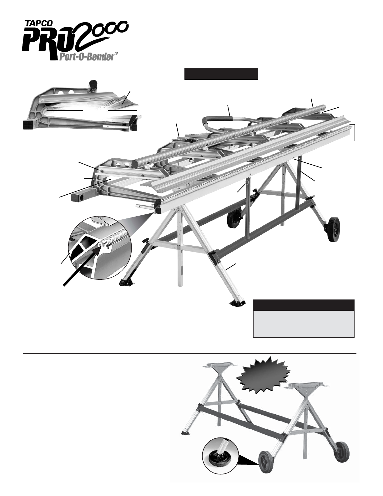
Inside Working Pockets
The largest in the industry!
➤
Exclusive, 19" throat depth, largest in the
industry for making larger, more complex
Super strong
redesigned die castings.
Exclusive 19"
throat depth
allows you to store
material inside of
bender reducing
handling and flipping
and speeding up
bending.
shapes faster and easier.
Pivot Arms
computer
19"
TAPCO PRO 2000®Port-O-Bender
Maximum Throat Depth • Expanded Capabilities
PRO 2000
enabling you to do your jobs faster, better and more efficiently.
➤
is specifically engineered for optimum use with all Tapco accessories
(See accessories p. 3 & 4 )
PRO 2000 Features
Locking Handle
Part of a strong, positive
clamping system.
Hemming Handle
TAPCO Pro-Filer
(optional accessory
see pg. 3)
Hinge Clip
(see page 6)
Bending/Lifting
Handle
Faspin
Pivot
Links
Opening
®
Jaw
3
/4"
1
Base Hinge
Patented “Moving Pivot” hinge,
the most advanced hinge design
in the world, increases leverage
and lifting power and eliminates
scratching or marring of materials.
o
(180
hemming capability)
Pro 2000 Port-O-Benders are made under one or more of the following U.S. Patents:
4,493,200, 4,445,356, 4,372,142, 4,766,757, 3,817,075, 4,557,132, 4,240,279, 4,671,094, 3,482,427, 4,494,397, 3,559,444,
5,343,728, 5,353,620, 5,505,069. Other U.S. and Foreign Patents Pending.
TAPCO PRO-STAND
3,161,223, 4,321,817, 4,651,553, 4,489,583,
™
Deluxe Heavy Duty Transportable Support
for your PRO 2000, PRO-III Port-O-Bender
and E-Z Angle Siding Table
Pro-Stand Features
• Durable lightweight anodized aluminum construction.
• Fast and easy height adjustments from 28" to 37".
• Heavy duty wheels handle the roughest of job site
terrains then convert to support pads.
• Detaches quickly from your Port-O-Bender.
• Fits all 8' 6" through 12' 6" Pro Series
Port-O-Benders and
Siding T able
.
E-Z Angle
Heavy Duty wheels
convert to foot pads
for solid support on
all terrains
2
TAPCO
Pro-Stand
(optional
accessory
see below)
PRO 2000 Bending Capacities
• Up to .030 soft aluminum
• Up to 28 ga. galvanized steel
• Up to 16 oz. copper sheet & coil
PRO 2000 HD Capacities
SOLID
SUPPORT AND
PORTABILITY
TOO!
(see pg. 8)
(See page 9
for Installation
Instructions)
U.S. & Foreign Pats. Pend.
Page 3
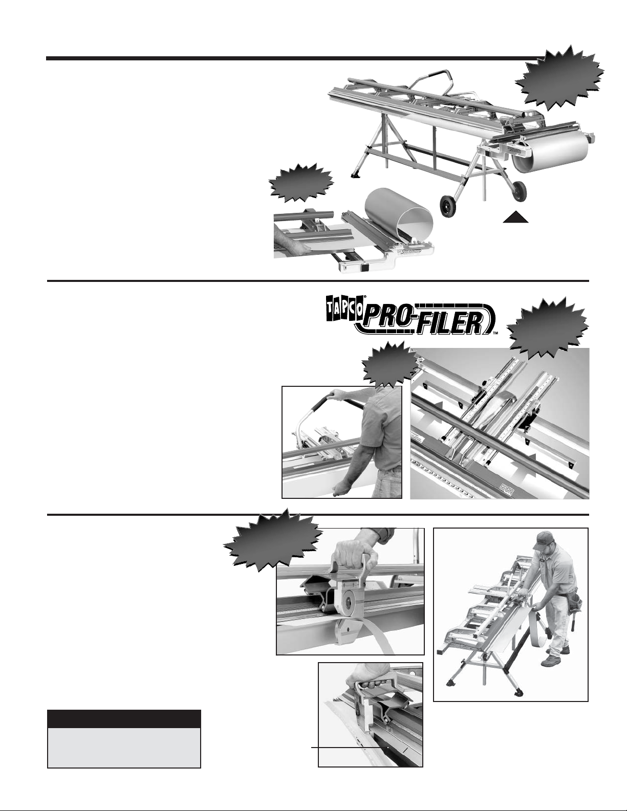
PRO 2000®
SIDE-WINDER
PORT-O-BENDER® ACCESSORIES
™
Coil Holder
Works in tandem with your Port-O-Bender
and CUT-OFF to form a complete “trim shop”
SIDE-WINDER Features
• Attaches in seconds to the end of your
Port-O-Bender,
• Allows you to feed coil directly into the jaws of
your
Port-O-Bender.
give you factory quality cross cuts. Speeds up
production, decreases waste.
• Helps eliminate damage from handling coil stock,
especially on windy days.
• Holds up to 24"x50' coil*. Weighs only 25 lbs.
When used with Pro-Stand.
*
• New improved versatility! Work both sides of your
coil. Coil can be drawn out finished side up or
down. See photos at right.
standard or heavy duty models.
Uses your
TAPCO PRO-FILER
PRO Series
PRO CUT-OFF
®
to
Speeds U
ending!
B
2000
Automatic Squaring and Measuring Gauge
PRO-FILER 2000 Features
• The
PRO-FILER
measure material fed into your Port-O-Bender,
need to mark and snip on your coil.
•
Automates your production. Saves up to 50% of your
layout time—the largest block of time that slows you
down the most!
• Easy to use as a template and profile maker.
•
PRO-FILER Strips
shapes. Simply form strips to your desired profile
then insert them into the
your bending.
• Turns rookies into pros in hours instead of years.
Makes pros more efficient.
is the first tool ever to automatically square and
store key information for bending
PRO-FILER
and they guide
eliminating the
Keeps
our
here y
.
ou
e coil at y
th
side–w
need it!
p
Saves up
to 50%
your tim
of
Note: When using the
the
PRO CUT-OFF
to cut off material. Both optional
accessories shown with
PRO 2000 Port-O-Bender
See Pro Cut-Off below.
e
SIDE-WINDER
must be used
ore
NO m
guesswork in
laying out
shapes
st
o
PRO CUT-OFF
Quickly, safely and easily
™
revo
sin
he m
T
lutio
ce th
ben
n
e p
ar
der
makes factory quality cut offs
right right on your Port-O-Bender
PRO CUT-OFF Features
• Lightweight aluminum construction built to last.
• Hardened and captured tool steel cutting
knives for safety and durability.
• Pays for itself by reducing scrap and eliminating knifing damage to costly bending hinges.
• Eliminates use of dangerous utility knives and shears.
•
Saves time and labor in scoring and breaking off material.
Also for use with Tapco
PRO CUT-OFF Capacities
• Up to .030 aluminum. All vinyl.
• Up to 28 ga. galvanized steel
• Up to 16 oz. copper
SIDE-WINDER.
Note: Shear point
remains constant
at 11/2" from your
Bending Edge.
y too
table
or
l
Using the
PRO CUT-OFF
The proper technique is to effortlessly
➛
➛
push your
material with a smooth, constant motion
from right to left. Do not stop in the mid-
➛
➛
11/2"
dle
Make
Pro Cut-Off
or cut with a back and forth motion.
sure hinge clip is engaged.
through the
U.S. & Foreign Pats Pend.
3
Page 4
TAPCO ACCESSORIES
A Necessity for Today’s Professional Sider
®
PRO-FILER 2000
— Reduces layout time
and need to snip mark
your coil for measuring.
—Simply feed coil in to your
Bender, the
you measure and square
in one operation.
Pro-Filer
(See page 3)
helps
SIDE-WINDER
— Saves time by allowing you
to roll out coil directly into the
jaws of your Port-O-Bender.
— Decreases coil damage due to
excessive handling especially
on windy days.
™
(See page 3)
PRO-STAND
— Solid support and mobility on
the job site.
— Adjustable, folds up and
detaches in seconds.
™
(See page 2)
OTHER MAJOR ITEMS
Ask your distributor for more information
E-Z ANGLE
Siding Table
®
Slitting & Rib Forming System
PRO CUT-OFF
— Quickly, safely & easily makes
factory quality cut offs right on
your Port-O-Bender.
— Saves time and labor in scoring
and cutting off material.
—Also for use with
PORT-O-SLITTER
™
(See page 3)
Side-Winder.
™
4
Page 5

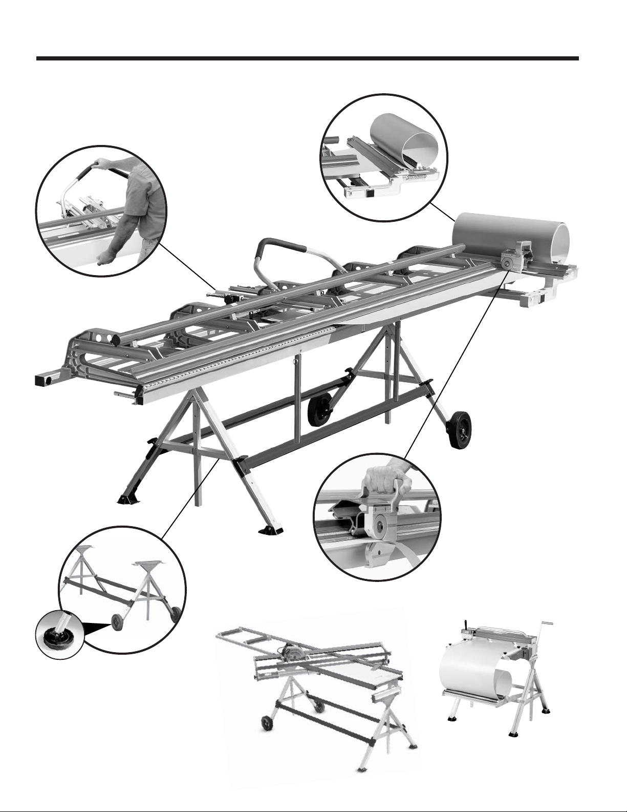
THE “PRO 2000 COMPLETE” SAVES TIME, INCREASES PROFITS
The “PRO 2000 Complete” system includes: Port-O-Bender, Pro Cut-Off, Side-Winder,
Pro-Filer 2000 and Pr o-Stand. On an average day, they can save you hour s on the job site!
Pro-Stand
time savings:
Pro-Stand
and transports your
1
all accessories around the job site.
Saving you time and effort.
Pro Cut-Off
time savings:
Pro Cut-Off
a factory edge in seconds. No need
4
to score and break off material. Saves
time, effort and reduces scrap.
provides solid support
PRO 2000
safely cuts the coil with
with
Side-Winder
time savings:
Side-Winder Coil Holder
coil directly into the jaws of your
2
5
No need for extra handling of
2000.
coil stock or separate layout table.
Pays off big on windy days.
Pro-Filer 2000
material fed into your
Saves time measuring and snipping
(See step 6).
coil.
automatically squares
PRO 2000.
dispenses
PRO
Pro Cut-Off
on the
3
Also the
duty cutting your coil to width. (See
step 4).
Tapco Pro-Filer
time savings:
In making bend after bend,
eliminates the need to mea-
2000
6
sure, mark and snip each piece of
coil, and ensures accuracy.
cuts your coil to length
Side-Winder
Pro Cut-Off
in seconds.
does double
Pro-Filer
PRO 2000 Hinge
time savings:
PRO 2000’s
pivot” hinge makes bending easier
7
(requires 35% less lifting) and
won’t scuff material, preventing
touch up work.
patented “moving
PRO 2000 Working Pockets, Throat
Depth time savings:
PRO 2000’s
ets and throat depth let you form
8
more complex shapes faster,
easier and better.
large working pock-
5
The
“PRO 2000 Complete” System
•
PRO 2000 Port-O-Bender
•
Pro-Stand
•
Side-Winder
•
Pro Cut-Off
•
Pro-Filer 2000
Saves you 1–2 hours on the
job site in an average day!
In Todays Busy
Economy You Have
to be “COMPLETE”
to Compete.
Page 6

SETTING UP YOUR PRO 2000
Hemming Handle Installation
Hemming
Handle
®
PORT-O-BENDER
®
Handle
Plug
Locking Handle
The PRO-III Hemming Handle Assembly includes: (1) Hemming Han-
dle, (2) Handle Plugs, (2) Faspins, (2)
Hex Bolts.
Faspin
Hex Bolt
Insert Hex Bolt through Locking Handle
of your Port-O-Bender and into base
of Hemming Handle as indicated using the 3/8" Hex Bolts provided. HAND
TIGHTEN ONL Y . Repeat for other side.
Lifting/Bending Handle Installation
Moving
Hinge
Lock Nut
T-Handle
Hex Key
1
/
-20
4
1
/
-20 x 11/2"
4
Screw
Handle
Plug
Faspin
Attach the Hemming Handle over the
Handle Plugs and secure them with
Faspins. Now tighten the 3/8
Bolts with a 9/16
" wrench. Handle can
" Hex
be detached from now on by simply removing the Faspins.
Lifting/
Bending
Handle
Remove the combination Lifting/Bending Handles from each end of the PortO-Bender by removing the Faspins as
shown.
Insert Handle Assembly into hole in
bottom of Moving Hinge. Align hole in
hinge with Handle Plug and insert
screw using T-Handle Hex Key as
shown. Secure with 1/4-20 Lock Nut.
Hinge Clip Installation
The Hinge Clip keeps the Moving Hinge in position for
ease of aligning material. It can also prevent rippling of
the coil during cut off operations.
To install Hinge Clip, locate predrilled hole on bottom
center of Moving Hinge. Align holes in Clip and Hinge
as shown and insert Phillips head screw provided.
Note:
You must use hinge clip when using Pro Cut-Off.
Secure
1
with
/
Lock Nut
-20
4
Repeat for other handle(s). To remove
handles, simply release Faspins. Always use more than one handle when
bending.
6
Page 7

ADJUSTING YOUR PRO 2000® PORT-O-BENDER
Pivot Link Adjustment Instructions
IMPORTANT: Your Port-O-Bender® incorporates an advanced new Micro-Adjust system that enables you to adjust the
gripping tension on material faster and easier than ever. The Pivot Links have been pre-set at the factory for average
holding capacity and ease of operation. However, it’s important that you readjust your Port-O-Bender® to your
stock thickness. Your Port-O-Bender
conditions. It is important that you follow these steps when you adjust your Port-O-Bender
tension and maximum performance.
®
may also need periodic adjustment due to extreme weather and/or working
®
to ensure proper gripping
®
First check the uniformity of the clamping pressure along the entire length
of your Port-O-Bender
®
by using the following method.
TO TEST —
Cut narrow strips of the stock which you will be using and lock one piece
under each frame casting as indicated in figure 1. Then move material from
left to right and try to pull material straight out. If material can be pulled out or
if the material does not move at all then the pivot links need to be adjusted. If
material can be moved from left to right but cannot be pulled out directly then
the pivot links are properly adjusted.
NOTE: All adjustments are
position. All adjustments are
Port-O-Bender® in the “locked” position.
Figure 1
Figure 2
TO ADJUST —
Insert the adjusting wrench provided into the Pivot Link Stud through
the access hole in the upper link. (See Figure 2.) Turn 1/4 turn
either
or
Repeat test step above to check tension.
COUNTER-CLOCKWISE
CLOCKWISE
to DECREASE locking tension.
to INCREASE locking tension
PRO 2000
Port-O-Bender
Pivot Link
Assembly
made
with the Port-O-Bender® in the “open”
tested
with strips of material placed in the
Decrease
Increase
Upper
Adjustment
Link
Pivot Link
Stud
Lower
Adjustment
Link
TO ADJUST (Optional method)—
As an alternate method you may use a 5/8" open-end wrench
directly on the Pivot Link Stud by turning 1/4 turn either
COUNTER-CLOCKWISE
CLOCKWISE
to DECREASE locking tension. (See Figure 3.)
to INCREASE locking tension or
Repeat test step above to check tension.
Figure 3
7
Page 8

USING THE PRO 2000
Basic Hemming and Folding
®
PORT-O-BENDER
®
Insert the material you wish to hem
1
into your Port-O-Bender.
Remove the material from the
4
Port-O-Bender.
Close and lock Bender on the
2
material.
Hemming
Pocket
Moving
Hinge
Position the bent edge of the ma-
5
terial in the Hemming Pocket on
top of the Anvil.
HEMMING POCKET
Material
Care and Maintenance of your Port-O-Bender
Your Tapco Port-O-Bender® is virtually maintenance free and will provide you
with years of reliable and trouble-free performance, however, there are a few
basic necessities required to keep your Port-O-Bender® like new.
1. Clean the clamping surfaces each day before using. Use only clean shop
towels that are free of dirt, oil and metal chips.
Bend as far as you can go.
3
Lift the Bending Handles and
6
compress the bend for a completed
hem.
®
PRO 2000 Bending Capacities
• Up to .030 soft aluminum
• Up to 28 ga. galvanized steel
• Up to 16 oz. copper sheet & coil
Capacities
2. Do not use your bender around your saw table as the cuttings may get in
between clamping surfaces and cause excessive wear or material scratching. Brush away any cuttings or filings that accumulate.
Transport your Port-O-Bender® in the unlocked position. You may transport
3.
it in the locked position if you clamp a piece of cardboard or vinyl siding
between the clamping surfaces.
4. If your material is getting scratched, examine the Stainless Bending Edge,
Base Hinge and Moving Hinge for roughness or burrs. Remove burrs with
emery cloth or replace excessively worn parts. Optional Pro Cut-Off will
help eliminate excessive wear to costly bending edge.
Use a lightweight spray oil along the moving pivot hinge after every
5.
40 hours of use.
8
PRO 2000 HD Bending Capacities
• Up to .040 soft aluminum
• Up to 26 ga.* galvanized steel
• Up to 18 oz. copper sheet & coil
MAX II commercial model Port-O-Benders are
*
available to bend up to 20 ga. galvanized steel.
Page 9

PRO-STAND INSTALLATION INSTRUCTIONS
DETAIL
Brake
Bracket
8
5
B
PRO 2000
PRO-III
Only
FRONT OF
BENDER
2 X 4
Bracket
1
DETAIL
A
“T” Knob
Pin
Cross Brace
Detail
Steps (indicated in diagram)
1. Remove all parts from box. Attach 2 x 4 Bracket to Vertical
Support using 1/4-20 x 1 1/2" Hex Bolt and 1/4-20 2Way Lock Nut.
2. Slide Vertical Support into End Assemblies, setting to
desired height, and secure with Faspin (part #10678).
3. Attach Wheel Assembly to End Assembly using 1/4-20 x
2 1/2" Hex Cap Bolt and 1/4-20 Two Way Lock Nut.
4. Fold wheels to pad position (as indicated in diagram)
and stand End Assemblies apart.
5. Attach both Cross Braces by seating pins into center
holes in legs and tightening the “T” Knobs into the top
threaded holes (see Detail A above).
6.Assemble Brake Brackets (see Detail B above) securing
with hex nuts. Repeat for other Bracket.
7.From bottom of Bender, align holes in Brake Brackets
with holes in Front and Back Rails of Bender. Insert
washer head screws and tighten Brake Brackets in place.
(*Pre '99 Benders will need to be drilled)
8
.
Turn Bender right side up and fit Brake Brackets into 2x4
brackets. Align holes in Brackets and insert Faspins. After
the Brake Brackets are installed on the Port-O-Bender,
entire unit can be quickly detached from Pro-Stand by
removing Faspins.
4
6
(INVERTED VIEW
OF BRAKE
BRACKETS)
7
3
2
BOTT OM VIEW
Faspins
9
Page 10

10539
10531
10550
10540
assembly
10521
10381
assembly
PIVOT LINK
EXPLODED
VIEW
10887
*10448
10536
10355
*10498
*10505
*10490
*12079
*10347
*10510
*10415
10539
10518
10524
10515
10351
assembly
(ships with 10349)
Common Parts
Part No. Part Name
10094 1/4-20 Hex Flange Nut
10347 Pivot Arm - Left
10348 Pivot Arm - Right
10349 Coupling Nut
10351 Lifting Handle Assembly
10355 Pivot Arm Cap
10503 1/4-20 x 2 1/2" Sock Cap Sc
10508 Locking Handle Pin
10515 10-24 x 1/2" Pan HD Sc
10518
10519
10520 1/4-20 Nylok Hex Nut
10521 Upper Link
10524 Lifting Handle Plug
10530 Rubber Pivot Pin Keeper
10531 Hemming Handle Plug
10532 3/8-16 x 3" Hex Cap Bolt
10534 3/8" Flat Washer
10535 3/8-16 Nylok Hex Nut
10536 3/8-16 x 2 1/4" Hex Bolt
10537
10538 3/8" Lock Washer
10539 1/4 x 1 1/4" Faspin
10540 Hemming Handle Assembly
10544 Lifting Handle Cap
10545 Moving Hinge Cap
1/4-20 x 1 1/2" Sock FL HD Sc
1/4-20 x 3/4" Hex Wash HD Sc
1/4-20 x 3/4" Sock Flat HD Sc
10549
10520
10542
10515
10094
10520
10535
10537
10508
10537
10347
10349
*10425
10547
10545
10519
Part No. Part Name
10547 Base Hinge Cap - Right
10548 Base Hinge Cap - Left
10549 Locking Handle Cap - Right
10550 Locking Handle Cap- Left
10551 Back Rail Cap
10552 Key Wrench Clip
10887 T-Handle Hex Key
11056 Pivot Assembly
12061 C Casting
Model Specific Parts
6'8"
10329
10331
10415
10425
10428
10448
10450
10490
10498
10507
10510
12079
12080
8'6"
10333
10335
10417
10430
10433
10452
10454
10491
10499
10506
10511
12081
12082
(* 6'8" part numbers shown in diagram)
10'6"
10337
10339
10419
10435
10438
10456
10458
10492
10500
10505
10512
12083
12084
10
10538
10530
12'6"
10341
10343
10421
10440
10443
10460
10462
10493
10501
10504
10513
12085
12086
10503
10534
*10329
12061
10551
NOTE: Multiple parts of the same
number may not all be called out.
14'6"
10345
—
10423
10445
—
10464
—
10494
10502
—
10514
12087
—
Part Description
Back Rail
HD Back Rail
Moving Hinge
Base Hinge
HD Base Hinge
Locking Handle
HD Locking Handle
Stainless Edge
Hinge Pin
Tape Measure
Vinyl Strip
Locking Anvil
HD Locking Anvil
10348
10532
10519
Page 11

TRADITIONAL BENDING TECHNIQUES
Helpful Hints for Trim Work
1. Measure the total length of the trim area to be covered and
divide by the length of your Bender to determine the number
and length of trim pieces needed.
2. Determine the dimensions of each section of the desired trim
shape by measuring the profile to be covered. As an aid, make
a pattern out of a 1" strip of coil to get your exact profile.
3. Transfer the dimensions in Hint #2 to each end of a piece of
trim coil by making a
These marks now become the bending points and makes
the bending marks visible from either side. On longer lengths
fold the coil over as shown and snip both ends at once. This
saves time and ensures accuracy. The Tapco Pro-Filer was
designed to make this time consuming part of your job easier
and more accurate. See page 3.
4. Lock the pre-marked coil blank into the bender with the cut
marks located directly under the outer edge of the Stainless
Bending Edge. Lock Bender. To cut off the coil with a razor
knife, score the metal against the Stainless Bending Edge.
bend the metal up and push back down by hand until the
Now
exposed
section breaks off. It may require 2 or 3 repetitions.
1
/4" slit in the metal with a pair of shears.
When braking material, bending to just 45° will avoid round-
ing the edge. The Pro Cut-Off was designed to safely and
easily cut your material in seconds. See page 3.
5. For bending, follow the suggested sequence of bends on
page 12. For bending techniques see “Bending the Roof Drip
Edge” below.
6. Don’t fit your trim parts too tight. This will complicate the
joints where parts overlap. A one inch (1") lap joint is enough
to allow for expansion and contraction.
Trim should be lapped
so that laps are facing away from traffic areas.
7. Try to nail the trim parts on an area that will make the nails
less conspicuous. Fasten at laps. When face nailing, use
just enough nails to secure trim; DO NOT DRIVE NAILS
TOO TIGHT!!
8.
Remember,
when designing shapes you are hanging a cover
over the wood parts, not laminating a skin-tight surface. This
is called “Floating Your Trim”. Allow for irregularities in the
wood because your formed trim shapes are straighter than
the wood trim moldings or boards you are covering.
9. With practice, you’ll learn to overbend or underbend certain
sections to achieve a pressure fit of your trim parts which
will, in turn, require fewer nails and give your job a more
wood-like appearance.
10. Hemming (making a 180° bend on the edge of a sheet) will
give your shape a “Factory Edge Look” and will stiffen the
entire trim piece to help eliminate “oil canning”. See page 8.
Bending the Roof Drip Edge
(Use these basic instructions for all examples)
1. This shape is basic to all the other shapes contained in this
manual. Practice this shape before you proceed with the other
trim pieces illustrated on pages 12.
2. To begin, cut off a piece of coil 4
foot long (As shown at right).
3. Mark your coil with a pencil at 2", 2
Then snip these marks in about
both sides of the coil).
4. Put your coil into the Bender with the Finished Side Up. Bend
1
is the 2
3
/4" mark, lock the Bender on the mark; then,
bend 90°.
5. Remove the coil from the Bender. Bend will be at the 2"
mark on the coil, now put the coil into the Bender with the
Finished Side Down. Lock the Bender on this 2" mark. Note
that Bend shows the symbol
be 180°. Bend this as far as it will go (about 165°). Then proceed to hem it in the Bender as shown on Page 8 in “Basic
Hemming and Folding”.
6. Now to Bend put your coil back into the Bender Finished
Side Up and lock on the 4
45° as shown to complete the shape.
2
3
3
/4 inches wide by about 1
3
/4" and 41/4" on both ends.
1
/4" (so they will be visible on
2
which means the bend is to
*
1
/4" mark. Bend this approximately
(continued on next page)
Roof Drip Edge
Finish
*
1
3
Finish
Side
Up
1. Numbers show the sequence of the bends; thus,
would be the first bend, the second bend, etc.
2."Finish Side Up" indicates that the finished or
exposed side of the trim is to be put into the Bender
FACING UP.
3. "Finish Side Down" indicates that the finished or
exposed side of the trim is to be put into the Bender
FACING DOWN.
The bend is to be 180°.
*
2
Side
Down
2"
3
11/2"
1
/2"
/4"
2"
3
2
/4"
1
/4"
4
Material: Aluminum coil 43/4 inches
wide x the desired length. (For
practice, use only about a 1 foot
length of coil)
Finish
Side
Up
1 2
12"
Mark with pencil
Then snip in from
edge 1/4"
2"
3
2
/4"
1
/4"
4
3
4
/4"
11
Page 12

EXAMPLES OF B ASIC SHAPES
NOTE: UP and DOWN refers to the clad, painted or FINISH SIDE of the material as it is placed into the Bender.
1. All Purpose Sill Trim
Down
2
1
Up
2
Down
Down
1
Down
7
4
Up
Down
5
6
3
Up
Up
2. Fascia Trim
Down
7. Counter Flashing
2
Down
1
Down
3
3. One Piece Soffit Mitre 8. Bric k Frieze
Down
3
Up
2
5
Up
4. Rake Trim with “J” Channel
Down
1
4
Up
9. “F” Channel/Inside Corner
Up
2
Down
Down
Down
Up
Down
Up
4
1
6
5
Down
3
Down
3
2
Down
4
5
1
Up
1
Up
5. Soffit or Frieze Trim
®
TAPCO PRODUCTS COMPANY
Plymouth, MI USA Phone: (734) 451-8272 • Fax: (734) 451-0702 • Web site: www.tapcoint.com
Down
2
Down
1
5
Down
3
Down
5
3
Up
Up
5
Up
Up
5
4
3
Down
2
Down
1
Down
Down
6
4
Up
10. Window or Door Casing
with “J” Channel
2
Down
4
Up
A DIVISION OF TAPCO INTERNATIONAL
1
Up
2
Down
3
Up
Down
4
5
Down
10815 B
T1015-LS 3/01
5
 Loading...