

Tapco Port-O-Slitter General Instructions, Set Up, Accessories And Manual To Using

Tapco Products Company
“The World Leader
in Specialty Tools
for the Professional”
®
®
Port-O-Slitter
OPERATIONS MANUAL
General instructions, set up, accessories and guide to using your
portable precision slitting, rib forming and perforating system.
Saves
hours on large
siding jobs!
Contents
General Instructions...2
Knife Set Up ................2
Accessory Set Up .......3
Parts List .....................4
Motor Set Up ...............5
Slitter Stand Set Up ....6
Optional Slitter
Cut-Off .....................7
Optional Knives .......... 8
Page
24" model
optional
Port-O-Slitter
Port-O-Slitter Stand,
Cut-Off and PRO-Coiler.
(see page 6)
with
U.S. & Foreign Pats. Pend.
Tapco
“The Siders Helper” use it in
the shop or on the job site.
Port-O-Slitter
is
PORT-O-SLITTER® SETUP AND OPERATION
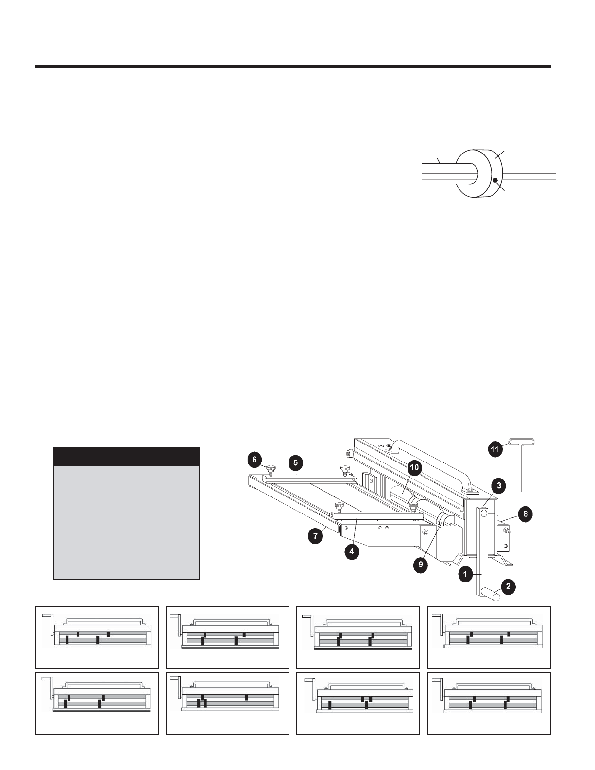
KNIFE
SHAFT
SET SCREW
1. ASSEMBLY OF YOUR PORT-O-SLITTER
Remove the contents of the PARTS BAG, which should include 2 “T” WRENCHES and the CRANK HANDLE
ASSEMBLY. Install the HANDLE and tighten the SET SCREW against the “flat” on the SHAFT. Make sure that the
HANDLE turns freely without interference.
2. PORT-O-SLITTER OPERATION—SLITTING
A. Loosen the SET SCREWS on the LOWER SLITTING KNIFE and slide the KNIFE
into the cutting position by aligning the cutting edge of the KNIFE with the desired
measurement on the TAPE MEASURE. Tighten the SET SCREW. IMPORTANT:
Tighten all SET SCREWS against the FLATS of the SHAFTS only. Carefully
slide the upper SLITTING KNIFE against the lower KNIFE and tighten that SET
SCREW securely using the “T” WRENCH provided. To avoid damaging the SLITTING KNIVES, do not “BANG” the KNIVES together when adjusting them. To make
more than one simultaneous cut repeat this procedure with the other KNIVES. If only one cut is being made, move
the remaining KNIVES at least three inches apart to avoid cutting or marking your material.
B. Next, adjust the right and left COIL GUIDE BARS. In most cases, set the right COIL GUIDE BAR at zero on the tape
measure, place the right edge of the material into the slot, then draw the left COIL GUIDE BAR to the left edge of the
material and tighten the knurled knobs. Periodically check COIL GUIDE BARS for squareness.
C. Now push the material into the SLITTER while turning the CRANK HANDLE counterclockwise.
NEVER PLACE HANDS OR CLOTHING NEAR KNIVES WHILE IN OPERATION.
D. For maximum performance during the slitting operation, keep the material flat over the front RECEIVER ROLLER
as the material exits.
E. When slitting harder and thicker materials, or if twisting of the material occurs, separate the KNIVES a few thou-
sandths of an inch to provide a better cut.
F. When slitting close to one edge of wide material, it may be helpful to lightly hold the material down on the COIL
TABLE surface in order to keep it from bowing upwards.
3. PORT-O-SLITTER OPERATION—RIB FORMING
A. To form “RIBS” for stiffening and decoration, set the KNIVES approximately 1/8" apart. Experiment to achieve
different effects. Refer to section 4 below for more information.
4. KNIFE CONFIGURATION AND SET-UP
• Standard KNIFE configurations which can be used are shown below.
QUICK GUIDE
1. CRANK HANDLE ASSEMBLY
2. CRANK HANDLE
3. CRANK HANDLE SET SCREW
4. RIGHT COIL GUIDE BAR
5. LEFT COIL GUIDE BAR
6. KNURLED KNOB
7. COIL TABLE
8. RECEIVER ROLLER
9. KNIFE
10. SHAFT
11. “T” HEX WRENCH (1 OF 2)
STANDARD KNIFE CONFIGURATIONS
KNIFE CONFIGURATION FROM FACTORY
CONFIGURATION FOR 1 SLIT
TWO SLITS SIMULTANEOUSLY
ONE SINGLE “RIB” FORM
TWO SINGLE “RIBS”
FORMED SIMULTANEOUSLY
ONE DOUBLE “RIB” FORMED DOWN
ONE DOUBLE “RIB” FORMED UP
2
ONE SLIT & ONE SINGLE “RIB”
FORMED SIMULTANEOUSLY
MAINTAINING AND LUBRICATING YOUR PORT-O-SLITTER
• Keep a light film of protective oil on the SHAFTS, DRIVE GEARS, SET SCREWS, and when not in service, the KNIVES.
Always inspect KNIVES for dirt and other foreign matter before using. Never clean knives while slitter is in operation.
•To clean knives, spread knives then run a soft cloth over the knife surfaces.
• The SLITTING KNIVES can be re-sharpened on a Surface or Blanchard Grinder. Grind ONLY the sides to regain a new
sharp edge. Do not grind the outside radius of the KNIVES.
• Periodically check the squareness of the stationary COIL GUIDE BAR with a framing square against the SHAFTS or
SLITTING KNIVES. Re-square when necessary.
• CAUTION: Always observe safe work practices when cleaning, maintaining and operating this equipment. To avoid injury,
keep your fingers, hands, clothing and other objects away from the SLITTING KNIVES when this machine is in operation.
ACCESSORY INSTALLATION:
PERFORATING ROLLS
INSTALL MALE ROLL ON TOP SHAFT,
FEMALE ON BOTTOM.
GROOVED KNIFE SET
INSTALL MALE ROLL ON TOP SHAFT,
PLACE SCRAPER IN GROOVE ON FEMALE
ROLL. SLIDE BOTH ON BOTTOM SHAFT.
NYLON PINCH ROLLERS
INSTALL DIRECTLY OVER EACH OTHER.
(SEE PAGE 8 FOR FURTHER DETAILS)
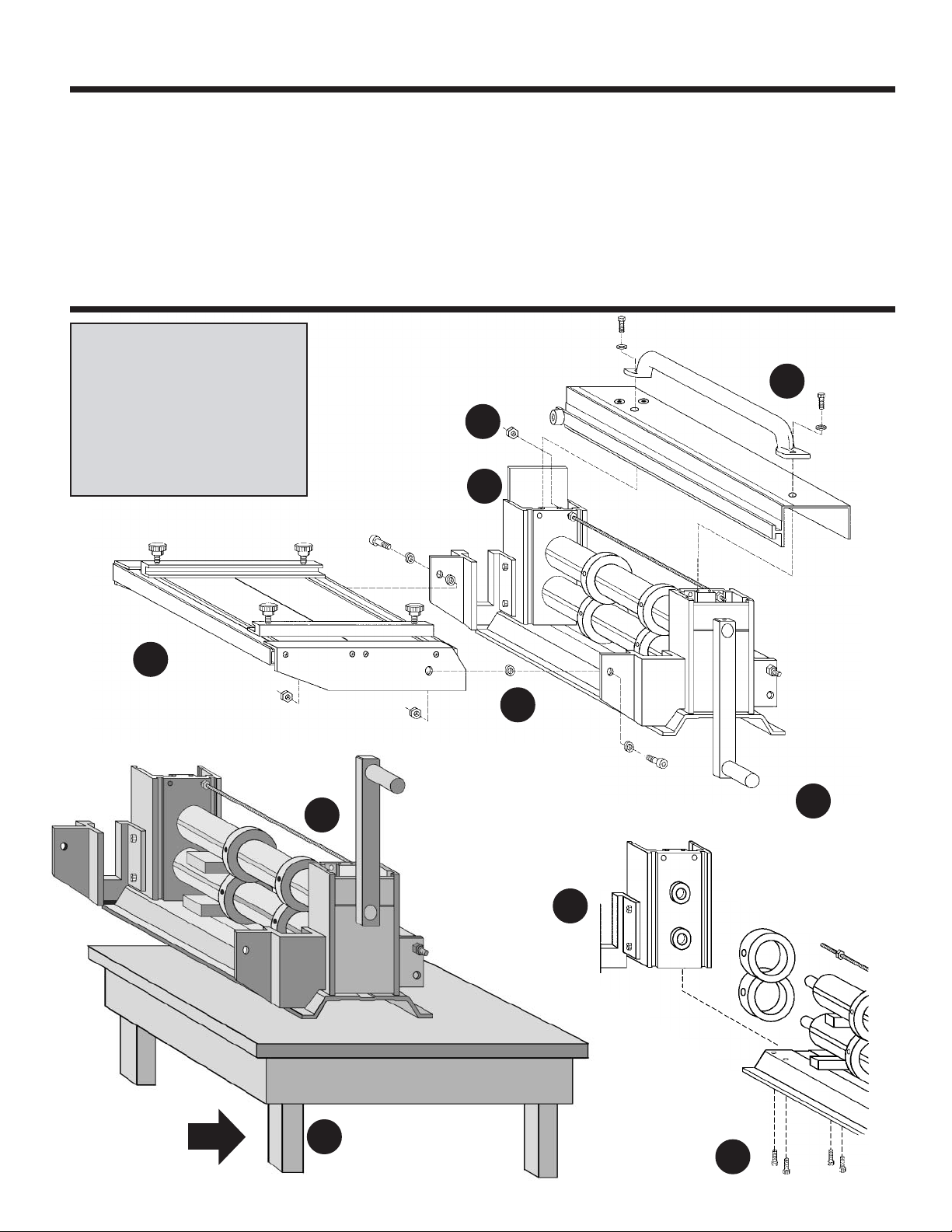
10
To reassemble, reverse the following
steps remembering to realign the tie
bar and receiver roller to the bearing
support as you slide it back in place.
Place wooden
shims under each
shaft for support.
6
Remove the
hex nut from
the tie bar.
Slide the end
cap out of the
bearing support.
Remove the coil table shoulder bolts,
nylon washers and nylox hex nuts. Set
coil table aside. The nylon washers
are of varying thicknesses, reinstall in
the same sequence as removal.
Gently tap bearing support free from
the shafts. At this point the front
receiver roller will dislodge. Set it to
the side. Make sure to reposition it
during reassembly.
Perforating Rolls, Grooved Knife Set, Nylon Pinch Rollers
Remove the handle cap screws
and washers, set handle and
cover aside.
2
4
3
5
9
After applying a light coating of oil to
all parts and surfaces, slide knives,
or perforating roll set onto shafts far
enough to be able to reattach
bearing support. Align set screws to
shaft flat. As a general rule, always
8
install perforating set to the end of
shafts.
START
Place slitter on a stable bench top
with end extended over edge just
1
enough to expose the 4 cap screws
underneath the bearing housing.
Remove all 4 cap screws from
underneath bearing support.
7
3
 Loading...