

Tapco MX Series, MX 10, MX 12, MX Stand, MX 8 Operating Instructions Manual
...
™
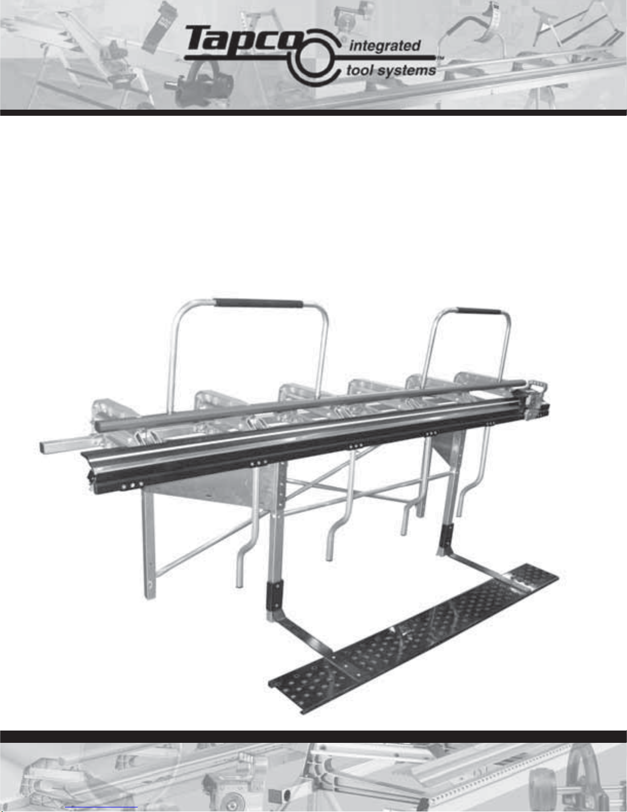
MX Series
Operating Instructions
MX 8™ • MX 10™ • MX 12™ • MX Stand™ • MAX Cut-Off
™
Snap StandMX Series
™
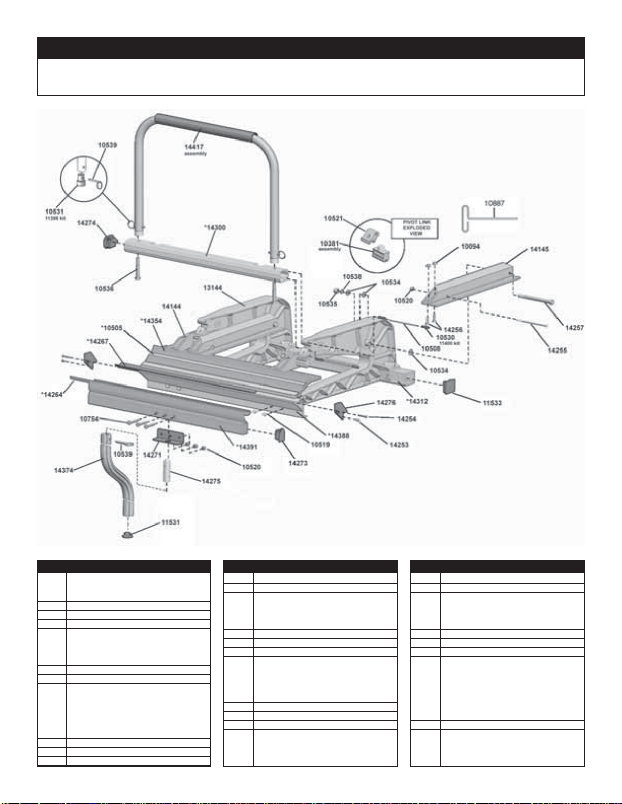
MX Series™ Brake Parts List
Item# Description Item# Description Item# Description
10491 8'6" Stainless Edge
10492 10'6" Stainless Edge
10493 12'6" Stainless Edge
10504 12'6" Tape Measure
10505 10'6" Tape Measure
10506 8'6" Tape Measure
10519 ¼ -20 x ¾ " Hex Wash HD Sc
10534 3/8" Flat Washer
10535 3/8-16 Nylock Hex Nut
10887 T-Handle Hex Key
11396 Pivot Link Assembly Kit (6)
11397 ¼ " x 1 ¼ " Faspin Kit (4)
11398 Locking Handle Plug Kit
Locking Handle Plug
3/8-16 x 2 ¼ " Bolt
11400 Locking bar Pin Kit
10 pins, 20 keepers
11531 Lifting Handle Cap
11533 Back Rail Cap
13144 C Castings
14144 Pivot Arm - Left
14145 Pivot Arm - Right
14253 8-32 x 5/16" Phil Pan HD Sc
14254 8-32 x 1" Phil Pan HD Sc
14256 ¼ -20 x 1" FL HD Sc
14257 3/8-16 x 5" Hex Cap Bolt
14263 8'6" Rubber Strip
14264 10'6" Rubber Strip
14265 12'6" Rubber Strip
14266 8'6" Wear Strip
14267 10'6" Wear Strip
14268 12'6" Wear Strip
14271 Lifting Handle Support Bracket (2)
14273 Moving Hinge Cap
14274 Locking bar Cap
14276 Fixed Hinge Endcap
14299 8'6" Locking bar
14300 10'6" Locking bar
14301 12'6" Locking bar
14311 8'6" Back Rail
14312 10'6" Back Rail
14313 12'6" Back Rail
2
14353 8'6" Locking Anvil
14354 10'6" Locking Anvil
14355 12'6" Locking Anvil
14374 Lifting Handle Assembly
14387 8'6" Fixed Hinge
14388 10'6" Fixed Hinge
14389 12'6" Fixed Hinge
14390 8'6" Moving Hinge
14391 10'6" Moving Hinge
14392 12'6" Moving Hinge
14414 Locking handle Assembly
14456 MX Series™ Brake Parts Bag 8'
14457 MX Series™ Brake Parts Bag 10'/12'
14480 Bolt and Nut Kit
¼ -20 x 4 ½ "" Bolt (5)
¼ -20 x Nylok Nut (5)
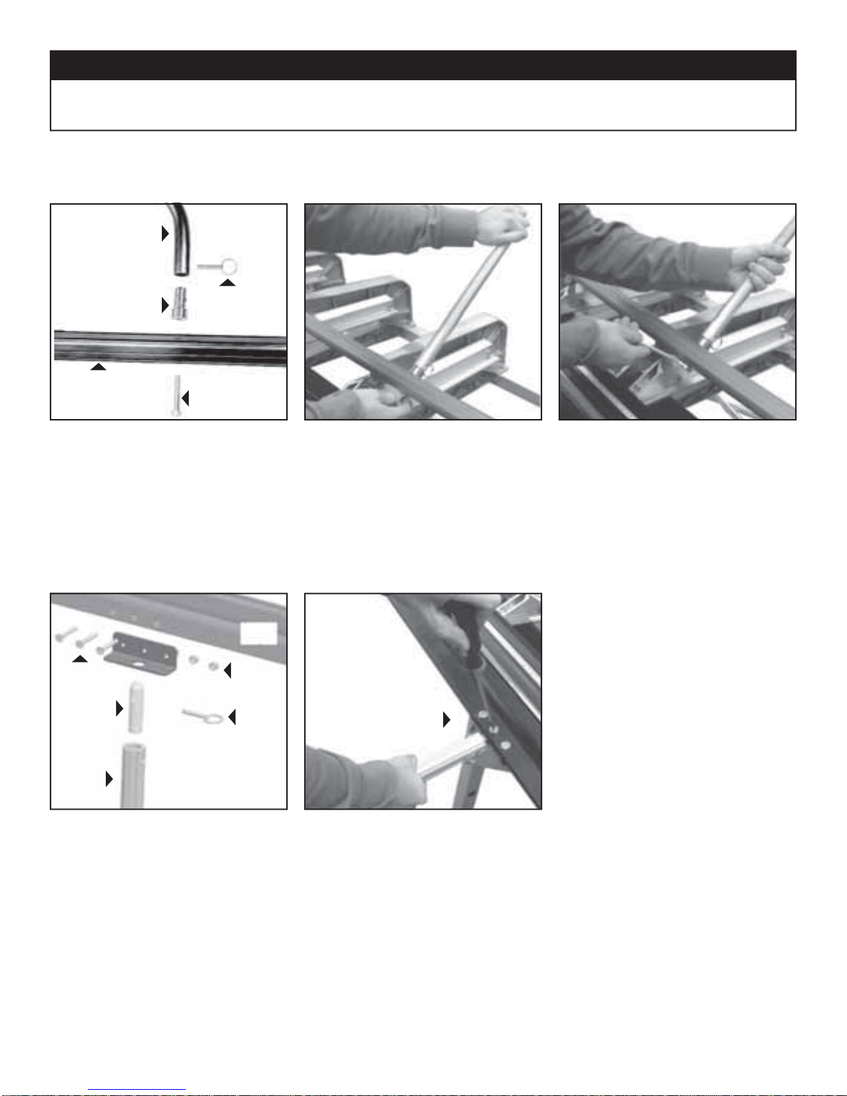
Locking bar Installation
Locking
Handle
Snap StandMX Series
™
Setting up the MX Series™ Brake
Handle
Plug
Locking Bar
MX Locking Bar Assembly includes:
Faspin
Hex Bolt
1. Insert Hex Bolt through Locking bar
(2) Locking bars,
(4) Handle Plugs, (4) Faspins, (4) Hex Bolts
Lifting/Bending Handle Installation
Moving
Hinge
1/4-20 x 1 1/2"
Screw
1/4-20
Lock Nut
of your MX Series™ Brake and into the
base of Locking bar(s) as indicated using the 3/8" Hex Bolts provided. HAND
TIGHTEN ONLY. Repeat for other side.
2. Attach the Locking bar over the Handle
Plugs and secure them with Faspins.
Now tighten the 3/8" Hex Bolts with a
9/16" wrench. Handle can be detached
from now on by simply removing the
Faspins.
Handle
Lifting/
Bending
Handle
Plug
Exploded view of
Handle Assembly
Faspin
1. First insert one end of the Handle Plug
into Lifting / Bending Handle and install
Faspin through holes.
Secure with
1/4-20 Lock Nut
2. Next, insert Handle Assembly into hole
in bottom of Moving Hinge. Align hole
in hinge with Handle Plug and insert
screw using Phillips Screw Driver as
shown. Secure with 1/4-20 Lock Nut
Repeat for other handles. To remove
handles, simply remove Faspins. Always use more than one handle when
bending.
3
Snap StandMX Series
™
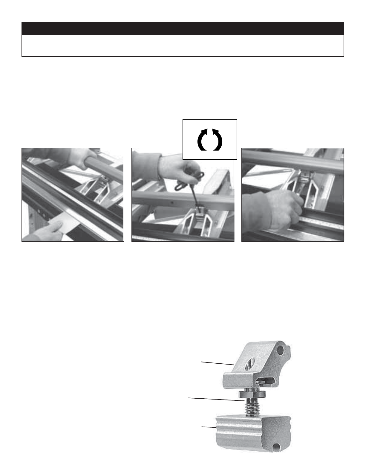
Pivot Link Adjustment Instructions
IMPORTANT: The Pivot Links on your MX Industrial Brake have been pre-set at the factory for average holding capacity and ease of
operation. However, it's important that you readjust your MX Industrial Brake to your stock thickness. Your MX Series™ Brake may
also need periodic adjustment due to extreme weather and/or working conditions. It is important that you follow these steps when you
adjust your MX Series™ Brake to ensure proper gripping tension and maximum performance.
First check the uniformity of the clamping pressure along the entire length of your MX Series™ Brake by using the following method.
Decrease
Increase
TO TEST
Cut some narrow strips of aluminum or use
strips from stock you will be using and lock
one under each shoe casting as indicated
above. Then lightly pull the material to
determine the tightness and uniformity
of each Pivot Link. If the material can be
moved when the MX handle is locked or if
it requires excessive pressure to lock the
handle down on the material then the Pivot
Arms may need adjustment.
NOTE: All adjustments are made with the
MX Series™ Brake in the “open" position.
All adjustments are tested with strips of
material placed in the MX Series™ Brake in
the “locked" position.
TO ADJUST
Insert the 3/16" hex wrench into the Pivot
Link Stud through the access hole in the
upper link. Turn 1/4 turn either COUNTERCLOCKWISE to INCREASE locking tension
or CLOCKWISE to DECREASE locking
tension.
Repeat test step above to check tension.
Pivot Link Assembly
Upper
Adjustment
Link
Pivot Link
Stud
Lower
Adjustment
Link
TO ADJUST (Optional method)-
As an alternate method you may use a 5/8"
open-end wrench directly on the Pivot Link
Stud by turning 1/4 turn either COUNTERCLOCKWISE to INCREASE locking tension
or CLOCKWISE to DECREASE locking
tension.
Repeat test step above to check tension.
4
 Loading...