

Page 1

Page 2

IMPORTANT SAFETY INSTRUCTIONS
1. Read these instructions.
2. Keep these instructions.
3. Heed all warnings.
4. Follow all instructions.
5. Do not use this apparatus near water.
6. Clean only with dry cloth.
7. Do not block any ventilation openings. Install in accordance with the manufacturer’s
instructions.
8. Do not install near any heat sources such as radiators, heat registers, stoves, or other
apparatus (including amplifiers) that produce heat.
9. Only use attachments/accessories specified by the manufacturer.
10. Unplug this apparatus during lightning storms or when unused for long periods of
time.
11. Refer all servicing to qualified service personnel. Servicing is required when the
apparatus has been damaged in any way, such as when liquid has been spilled or
objects have fallen into the apparatus, the apparatus has been exposed to rain or
moisture, does not operate normally, or has been dropped.
FCC Information
NOTE: This equipment has been tested and found to comply with
the limits for Class B digital devices, pursuant to Part 15 of the FCC
Rules. These limits are designed to provide reasonable protection
against harmful interference when the equipment is operated in
a commercial installation. This equipment generates, uses, and
can radiate radio frequency energy and, if not installed and used
in accordance with the instruction manual, may cause harmful
interference to radio communications. Operation of this equipment in a residential area is likely to cause harmful interference in
which case the user will be required to correct the interference at
his own expense.
Product Serial #:
Purchased at:
Date of purchase:
Part No. 0017142 Rev. A 10/05
©2005 LOUD Technologies Inc. All Rights Reserved.
2
Page 3

CONTENTS
IMPORTANT SAFETY INSTRUCTIONS ......................................................2
INTRODUCTION .........................................................................................................4
The Link.MIDI 4x4 USB MIDI Interface ....................................4
Link.MIDI 4x4 Features ...................................................................4
GETTING STARTED ..................................................................................................5
Connecting the Link.MIDI 4x4 .....................................................5
Hookup Diagram ................................................................................6
LINK.MIDI 4X4 FEATURES ...................................................................................8
Front Panel ............................................................................................8
1. INPUT 2-4 .....................................................................................8
2. OUTPUT 4 .....................................................................................8
3. ACTIVITY Indicators ................................................................8
4. USB/THRU Switch .....................................................................8
5. POWER Indicator ......................................................................9
Rear Panel .............................................................................................9
6. INPUT 1 ..........................................................................................9
7. OUTPUT 1-3 ................................................................................9
8. USB Connector ...........................................................................9
9. Kensington Security Slot ........................................................9
APPENDIX A: SERVICE INFORMATION .................................................10
Warranty Service .............................................................................10
Troubleshooting ...............................................................................10
Repair ...................................................................................................11
APPENDIX B: LINK.MIDI 4X4 SPECIFICATIONS .............................12
TAPCO LIMITED WARRANTY .......................................................................14
Don’t forget to visit our website at www.tapcogear.com
for more information about this and other TAPCO products.
3
Page 4

INTRODUCTION
Thank you for purchasing the TAPCO Link.MIDI 4x4 USB MIDI
Interface for digital recording systems equipped with a USB port on
either a Macintosh or a PC.
The Link.MIDI 4x4 is a 4x4 USB MIDI interface that is powered
directly off the USB connection so no external power supply is required.
Since it uses the USB drivers in the operating system of the computer
(Windows XP and OS X), no drivers are required to be installed.
The Link.MIDI 4x4 USB MIDI Interface
The Link.MIDI 4x4 is typically used to interface MIDI keyboards or
other MIDI instruments and devices to MIDI sequencing software on a
computer. It provides four MIDI inputs and four MIDI outputs on standard
5-pin MIDI connectors. A USB connector transfers the MIDI data to
and from a PC or Macintosh computer. Since each MIDI connector can
transmit MIDI data for up to 16 channels, the Link.MIDI 4x4 can handle
up to 64 channels of MIDI data.
Link.MIDI 4x4 Features
• 4-In, 4-Out MIDI Interface (64x64 MIDI channels)
• High-speed USB connection to PC or Macintosh computers
• USB/THRU switch routes MIDI IN 1 to MIDI OUTS 1-4
• MIDI IN and MIDI OUT activity indicators for each port
• USB powered (requires no external power supply)
• Convenient collapsible swivel-foot for desktop operation
• Compact size
Link.MIDI 4x4 Minimum System Requirements
PC Requirements
• Windows XP (SP1)
Macintosh Requirements
• OS X (10.3 or later)
4
Page 5
GETTING STARTED
IN
OUT
1 2 3 4
POWER
USB
THRU
USB MIDI INTERFACE
LINK.midi 4x4
ACTIVITY THRU
OUTPUT
INPUT
2 3 4 4
LOOK
CLOSER
USB
OUTPUT
INPUT
1
1
2
3
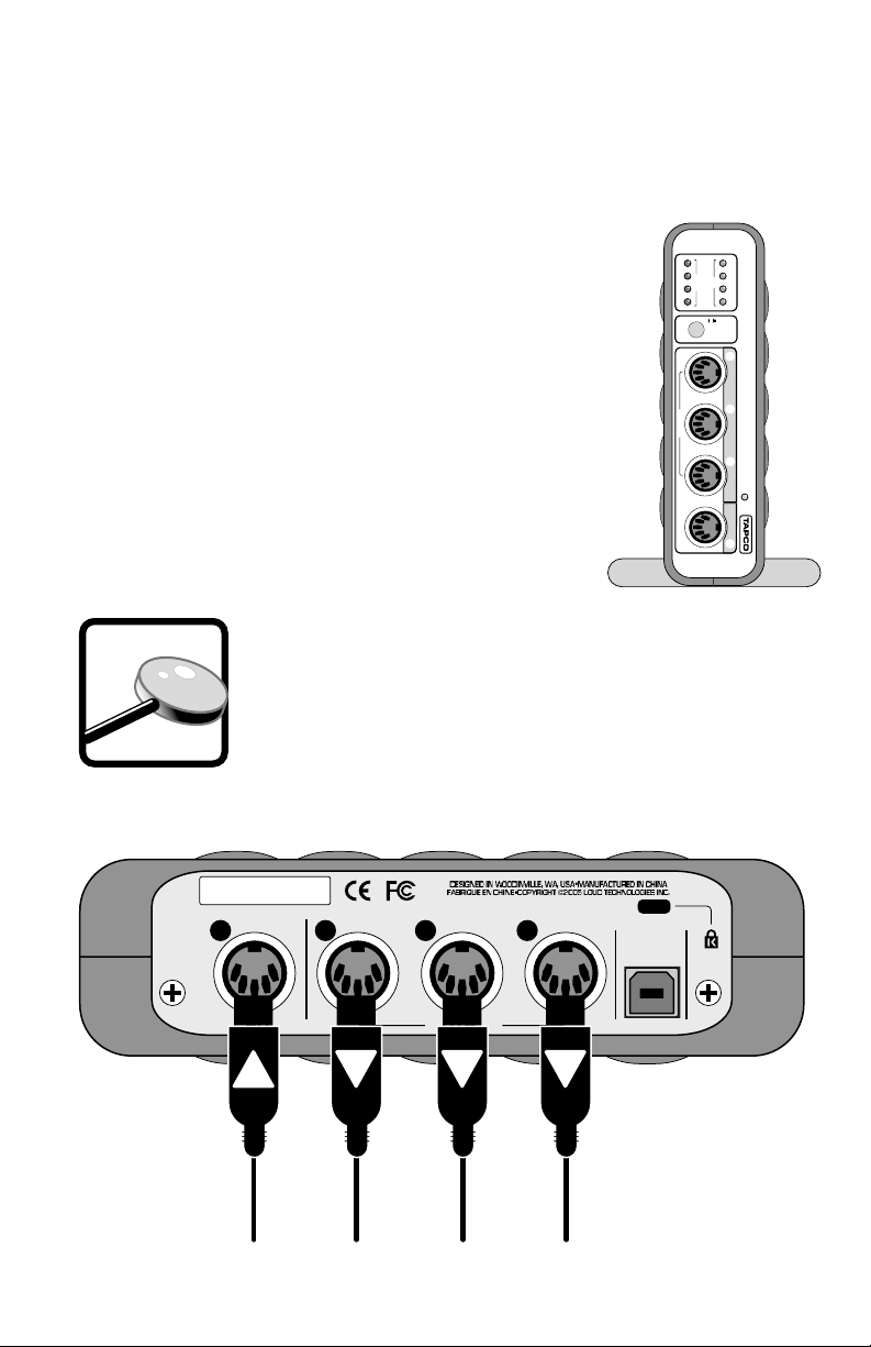
Use this section to get your Link.MIDI 4x4 set up quickly.
Connecting the Link.MIDI 4x4
• To stand the Link.MIDI 4x4 upright, pull the
stabilizer bar downward and twist it out 90º from
the body, as shown here.
• Connect your MIDI keyboard(s) and other MIDI
equipped instruments or sound modules to the
MIDI IN ports on the Link.MIDI 4x4.
• Connect the USB port on the Link.MIDI 4x4 to the
USB port on your computer using the USB cable
included in the box.
• Configure the Link.MIDI 4x4 in your application
software.
Many MIDI Interface applications require connecting
just one keyboard or MIDI controller to INPUT 1 and
using multiple MIDI outputs. This is why INPUT 1 is
located on the back of the Link.MIDI 4x4 along with
OUTPUTS 1-3. This keeps all the cables in the back and
out of the way.
5
Page 6

Hookup Diagram
•• ••••• •••• ••••••• •••• •••• •••• ••
•••
• •••• •••••• •••• ••• •••
•••• ••••••• ••••• •
•••
•• •••• •••• ••••• •••••• •••• •••• ••• •••• ••
Typical MIDI Studio Setup
This diagram demonstrates a typical MIDI studio setup. The USB
port on the Link.MIDI 4x4 is connected to a computer running MIDI
sequencing and music production software. The MIDI ports on a
keyboard are connected to I/O 1 on the Link.MIDI 4x4, and a MIDI
synthesizer is connected to I/O 2. You might connect a MIDI control
surface to I/O 3, which can be used to control various functions in the
software application. I/O 4 could be used for connecting a second MIDI
synthesizer, drum pads, or a wind controller.
6
Page 7

If there is an unused MIDI input, it could be used to input MIDI Time
Code (MTC) from a drum machine or other sync source.
Confi guration
You will need to confi gure your operating system to use the Link.MIDI 4x4.
Windows XP: Click Start > Settings > Control Panel. Double-click
“Sounds and Audio Devices” and click the “Audio” tab. In the “MIDI music
playback” drop down box, select one of the four USB Audio Devices
representing the four MIDI inputs as the default MIDI playback device.
Mac OS X: In the Finder, click Applications > Utilities > Audio MIDI
Setup. Under “MIDI Devices,” select the TAPCO Link MIDI USB as the
default MIDI device.
Link.MIDI 4x4 Default MIDI Device in OS X Audio MIDI Setup
Your MIDI software application may need to be confi gured to use the
Link.MIDI 4x4 as well. Each application is diff erent in the way that this
is done, but in general there will be a “Settings” or “Setup” window that
allows you to do this. In Tracktion 2, our easy-to-use music production
software application, it is located under the “Settings” tab, in the “Audio
Devices” window.
Link.MIDI 4x4 Default MIDI Device in Tracktion 2
7
Page 8

IN
OUT
1 2 3 4
POWER
USB
THRU
USB MIDI INTERFACE
LINK.midi 4x4
ACTIVITY THRU
OUTPUT
INPUT
2 3 4 4
LINK.MIDI 4X4 FEATURES
Front Panel
1. INPUT 2-4
These are standard 5-pin MIDI input connectors. Connect the MIDI
OUT ports from your MIDI-equipped devices to these input connectors.
2. OUTPUT 4
This is a standard 5-pin MIDI output connector. Connect this to the
MIDI IN ports on your MIDI-equipped devices.
3. ACTIVITY Indicators
There are four MIDI IN indicators and four MIDI OUT indicators.
Anytime there is data transferred at any of the MIDI ports, its
corresponding ACTIVITY indicator lights.
4. USB/THRU Switch
The Link.MIDI 4x4 has two modes of operation, USB mode and
THRU mode.
USB: When this switch is out, the Link.MIDI 4x4 operates with four
independent MIDI inputs and four independent MIDI outputs, all routed
through the USB port to your computer’s music production software
application, which manages the routing of MIDI data to and from your
computer.
THRU:
is routed to OUTPUTS 1-4. In THRU mode, INPUTS 2-4 do not function
there is no MIDI data transferred via the USB connection. This is useful
when you want to have one MIDI controller connected to two, three, or
four sound modules or sequencers.
When this switch is pushed in, MIDI data appearing at INPUT 1
and
3
8
5
214
Page 9

Note: The USB port must be connected to the computer in
USB
OUTPUT
INPUT
1
1
2
3
THRU mode to power the Link.MIDI 4x4, even though data
is not transferred over the USB cable.
5. POWER Indicator
The Link.MIDI 4x4 is powered from the USB port. There is no power
switch, so this LED lights up whenever the Link.MIDI 4x4 is connected to
the USB port on your computer (and the computer is powered on).
Rear Panel
6. INPUT 1
This is a standard 5-pin MIDI input connector. Connect this to the
MIDI OUT port on your MIDI-equipped device.
7. OUTPUT 1-3
These are standard 5-pin MIDI output connector. Connect these to
the MIDI IN ports on your MIDI-equipped devices.
8. USB Connector
This is the main connection between the Link.MIDI 4x4 and the host
computer. Use the USB cable provided to connect this port to a USB port
on your computer.
9. Kensington Security Slot
To help prevent theft, the Link.MIDI 4x4 has a security slot designed
to fit the popular Kensington security locks. A variety of models are
available from their website at www.kensington.com.
9
6 7 8
9
Page 10

APPENDIX A: SERVICE INFORMATION
Warranty Service
Details concerning Warranty Service are spelled out in the Warranty
section on pages 14-15.
If you think your TAPCO Link.MIDI 4x4 has a problem, please do
everything you can to confirm it before calling for service. Doing so might
save you from the deprivation of your Link.MIDI 4x4 and the associated
suffering.
These may sound obvious to you, but here are some things you can
check. Read on.
Troubleshooting
No Power
• Our favorite question: Is it plugged in? Make sure the USB cable
is connected between your computer and the Link.MIDI 4x4. The
computer must be on to provide power to the Link.MIDI 4x4 over the
USB connection.
•
Is the POWER LED illuminated? If not, try connecting the Link.MIDI
4x4 to another USB port on the computer (if available).
Lonely? Looking for that special someone?
Do you have a question about your TAPCO Link.USB 4x4?
Please call our Technical Support chaps at 1-877-827-2669,
Monday to Friday, from 7 am to 5 pm PST.
After hours, visit www.tapcogear.com and look under Contact Us,
or e-mail us at techmail@tapcogear.com
10
Page 11

Repair
Service for TAPCO products is available at a factory-authorized
service center. Service for TAPCO products living outside the United
States can be obtained through local dealers or distributors.
If your Link.MIDI 4x4 needs service, follow these instructions:
1. Review the preceding troubleshooting suggestions. Please.
2. Call Tech Support at 1-877-827-2669, 7 am to 5 pm PST, to explain
the problem and obtain a Service Request Number. Have your Link.
MIDI 4x4 serial number ready.
You must have a Service Request Number before you can obtain
factory-authorized.
3. Keep this owner’s manual. We don’t need it to repair the Link.MIDI
4x4.
4.
Pack the Link.MIDI 4x4 in its original package, including endcaps and
box. This is VERY IMPORTANT. When you call for the Service Request
Number, please let Tech Support know if you need new packaging. You
can order new packaging through our parts department. TAPCO is not
responsible for any damage that occurs due to non-factory packaging.
5. Include a legible note stating your name, shipping address (no
P.O. boxes), daytime phone
description of the problem, including how we can duplicate it.
6. Write the Service Request Number in BIG PRINT on top of the box. Units
sent to us without the Service Request Number will be refused.
7. Tech Support will tell you where to ship the unit for repair. We
suggest insurance for all forms of cartage.
8. You will need to contact the authorized service center for their
latest turn-around times. The Link.MIDI 4x4 must be packaged in its
original packing box, and must have the Service Request Number on
the box. Once it’s repaired, the authorized service center will ship it
back by ground shipping, pre-paid (if it was a warranty repair).
Note: Under the terms of the warranty, you must ship or drop-off the unit
to an authorized service center. The return ground shipment is covered
for those units deemed by us to be under warranty.
Note: You must have a sales receipt from an Authorized TAPCO Dealer
to qualify for a warranty repair.
number, RA number, and a detailed
11
Page 12

APPENDIX B: LINK.MIDI 4X4 SPECIFICATIONS
System Requirements
PC: Windows XP (SP1)
USB port
Macintosh: OS X 10.3 or higher
Native USB port (G3/G4 accelerator cards not
supported)
Physical Dimensions and Weight
Height: 1.7 in/43 mm
Width: 6.1 in/155 mm
Depth: 6.8 in/173 mm
7.6 in/193 mm with handles
Weight: 1.4 lb/0.6 kg
Disclaimer
Since we are always striving to make our products better by incorporating
new and improved materials, components, and manufacturing methods, we
reserve the right to change these specifications at any time without notice.
“TAPCO” is a registered trademark of LOUD Technologies Inc. All other brand
names mentioned are trademarks or registered trademarks of their respective
holders, and are hereby acknowledged.
©2005 LOUD Technologies Inc.
All Rights Reserved.
12
Page 13

IN
OUT
1 2 3 4
POWER
USB
THRU
USB MIDI INTERFACE
LINK.midi 4x4
ACTIVITY THRU
OUTPUT
INPUT
2 3 4 4
USB
OUTPUT
INPUT
1
1
2
3
13
Page 14

TAPCO LIMITED WARRANTY
A. LOUD Technologies Inc. warrants all materials, workmanship and proper operation
of this TAPCO product for a period of one year from the original date of purchase.
If any defects are found in the materials or workmanship, or if the product fails to
function properly during the applicable warranty period, LOUD Technologies, at its
option, will repair
sold and delivered within the U.S. by LOUD Technologies or its authorized dealers.
B. Failure to register online or return the product registration card will not void the
one-year warranty.
C. Service and repairs of TAPCO products are to be performed only at a factory-
authorized service center. Unauthorized service, repairs, or modification will void
this warranty. To obtain repairs under warranty, you must have a copy of your sales
receipt from the authorized TAPCO dealer where you purchased the product. It is
necessary to establish purchase date and determine whether your TAPCO product
is within the warranty period.
D. To obtain factory-authorized service:
1. Call TAPCO Technical Support at 877/827-2669, 7 AM to 5 PM Monday
through Friday (Pacific Time) to get a Service Request Number. Products returned
without a Service Request Number will be refused.
2. Pack the product in its original shipping carton. Also include a note explaining
exactly how to duplicate the problem, a copy of the sales receipt with price and date
showing, and your return stree address (no P.O. boxes or route numbers, please!).
If we cannot duplicate the problem or establish the starting date of your Limited
Warranty, we may, at our option, charge for service time.
3. Ship the product in its original shipping carton, freight prepaid, to the authorized
service center. The address of your closest authorized service center will be given to
you by Technical Support.
IMPORTANT: Make sure that the Service Request Number is plainly written on
the shipping carton.
E. LOUD Technologies Inc. reserves the right to inspect any products that may be the
subject of any warranty claims before repair or replacement is carried out. LOUD
Technologies may, at our option, require proof of the original date of purchase
in the form of a dated copy of the original dealer’s invoice or sales receipt. Final
determination of warranty coverage lies solely with LOUD Technologies Inc.
F. TAPCO products returned to one of the LOUD Technologies factory-authorized
service centers and deemed eligible for repair or replacement under the terms
of this warranty will be repaired or replaced within thirty days of receipt. LOUD
Technologies and its authorized service centers may use refurbished parts for repair
or replacement of any product. Products returned to LOUD Technologies that do
not meet the terms of this Warranty will not be repaired unless payment is received
for labor, materials, return freight, and insurance. Products repaired under warranty
will be returned freight prepaid by LOUD Technologies to any location within the
boundaries of the USA.
or replace the product. This warranty applies only to equipment
14
Page 15

G. LOUD Technologies warrants all repairs performed for 90 days or for the remainder
of the original warranty period. This warranty does not extend to damage resulting
from improper installation, misuse, neglect or abuse, or to exterior appearance. This
warranty is recognized only if the inspection seals and serial number on the unit
have not been defaced or removed.
H. LOUD Technologies assumes no responsibility for the quality or timeliness of repairs
performed by Authorized TAPCO Service Centers.
I. This warranty is extended to the original purchaser and to anyone who may
subsequently purchase this product within the applicable warranty period. A copy of
the sales receipt is required to obtain warranty repairs.
J. This is your sole warranty. LOUD Technologies Inc. does not authorize any third
party, including any dealer or sales representative, to assume any liability on behalf
of LOUD Technologies or to make any warranty for LOUD Technologies Inc.
K. THE WARRANTY GIVEN ON THIS PAGE IS THE SOLE WARRANTY GIVEN BY
LOUD TECHNOLOGIES INC. AND IS IN LIEU OF ALL OTHER WARRANTIES,
EXPRESS AND IMPLIED, INCLUDING THE WARRANTIES OF MERCHANTABILITY
AND FITNESS FOR A PARTICULAR PURPOSE. THE WARRANTY GIVEN
ON THIS PAGE SHALL BE STRICTLY LIMITED IN DURATION TO ONE YEAR
FROM THE DATE OF ORIGINAL PURCHASE FROM AN AUTHORIZED TAPCO
DEALER. UPON EXPIRATION OF THE APPLICABLE WARRANTY PERIOD, LOUD
TECHNOLOGIES INC. SHALL HAVE NO FURTHER WARRANTY OBLIGATION
OF ANY KIND. LOUD TECHNOLOGIES INC. SHALL NOT BE LIABLE FOR
ANY INCIDENTAL, SPECIAL, OR CONSEQUENTIAL DAMAGES THAT MAY
RESULT FROM ANY DEFECT IN THE TAPCO PRODUCT OR ANY WARRANTY
CLAIM. Some states do not allow exclusion or limitation of incidental, special, or
consequential damages or a limitation on how long warranties last, so some of
the above limitations and exclusions may not apply to you. This warranty provides
specific legal rights and you may have other rights which vary from state to state.
Please keep your sales receipt in a safe place.
15
Page 16

 Loading...