

Page 1

CMS
CEILING MONITOR SYSTEMS
INSTALLATION MANUAL
CMS
Tannoy United Kingdom T: 00 44 (0) 1236 420199 E: enquiries@tannoy.com
Tannoy Deutschland T: 00 49 (180) 1111 881 E: anfragen@tannoy.com
Tannoy France T: 00 33 (0)1 7036 7473 E: ventes@tannoy.com
TC|Group Americas T: 00 1 (519) 745 1158 E: info@tcgroup-americas.com
Tannoy adopts a policy of continuous improvement and product specification is subject to change.
REVISION DATE: 2ND NOVEBER 2009
6481 0480
CMS 501 models TEMPLATE HOLE CUTOUT SIZE: 190mm
CMS 501 BM
CMS 501 DC BM
CMS 501 PI
CMS 501 DC PI
CMS 501 PI back-can
CMS 601 BM
CMS 601 DC BM
CMS 601 PI
CMS 601 DC PI
CMS 601 PI back-can
CMS 601 models TEMPLATE HOLE CUTOUT SIZE: 253mm
Page 2

CMS
CONTENTS
1. INTRODUCTION
INTRODUCTION
1
2
UNPACKING
SAFETY NOTICES
3
PRODUCT FEATURE IDENTIFICATION
4
ACCESSORIES
5
INSTALLATION GUIDE
6
6.1
MECHANICAL INSTALLATION GUIDE FOR SUSPENDED CEILINGS
6.2
MECHANICAL INSTALLATION GUIDE FOR SHEET-ROCK CEILINGS
6.3
MECHANICAL INSTALLATION INSTRUCTIONS FOR OPTIONAL PLASTER RING
6.4
INSTRUCTIONS FOR OPTIONAL PRE-INSTALLATION BACK-CAN (PI MODELS ONLY)
Thank you for purchasing this Tannoy Ceiling Monitor System product. This product range is suited
for high-level music and speech reinforcement applications requiring exceptional sonic quality with
uncompromised reliability.
2. UNPACKING
Every Tannoy product and accessory is carefully inspected before packing. After unpacking, please
inspect your product to make sure no damage has occurred in transit. In the unlikely event of any
damage, would you please notify your dealer immediately and retain your shipping carton, as your
dealer may ask you to return the faulty unit to him for inspection.
Each CMS loudspeaker is packed in pairs and provided with the following accessories as standard;
C Ring, tile-bridge kit, grille, cut-out template, and paint mask. A plaster (mud) ring is also available
as an optional extra.
3. SAFETY NOTICES
Some regional construction codes require the use of a secondary method of securing loudspeakers
in ceiling to provide security of a back up support. A secondary support line should be attached from
the safety loop on the rear of the product to a source point on the ceiling. For PI models, the secondary
support line should be attached from the back of the driver chasis to a source point on the ceiling. Please
.
consult the relevant construction codes in your region.
7
WIRING AND SETTING UP
8
DIMENSIONS
8.1
CMS 501 DIMENSIONS
8.2
CMS 601 DIMENSIONS
9
TECHNICAL SPECIFICATIONS
10
PAINTING
11
WARRANTY
12
DECLARATION OF CONFORMITY
When using a power driver to install the product it is essential to use the correct torque level settings
to avoid over tightening and damage to the ceiling material or clamps.
Recommended torque setting: 1.5Nm
Tannoy will not be held responsible for any damages caused by the improper installation of these
loudspeakers.
Electrical Safety Notice: to comply with the standard UL1480, metal-clad flexible conduit (BX) is
required for connection to the terminal block for proper earth grounding.
In order to comply with UL regulations, the PI back-can must always be used with the CMS PI models.
SAFETY NOTE:
In order to comply with relevant fire safety regulations (i.e. BS 5839:1998), it is required that in the event of fire,
that failure of the circuit to which the loudspeaker is connected does not occur before evacuation of the building is
complete. Suitable measures include: a) use of terminal blocks (for connection to primary) with a melting point of not less than 650°C, for example
constructed from ceramic materials;
b) use of terminal blocks of a lower melting point but protected with thermal insulation;
c
) use of terminal blocks such that, on melting, an open-circuit or a short-circuit does not occur.
2
3
Page 3
CMS
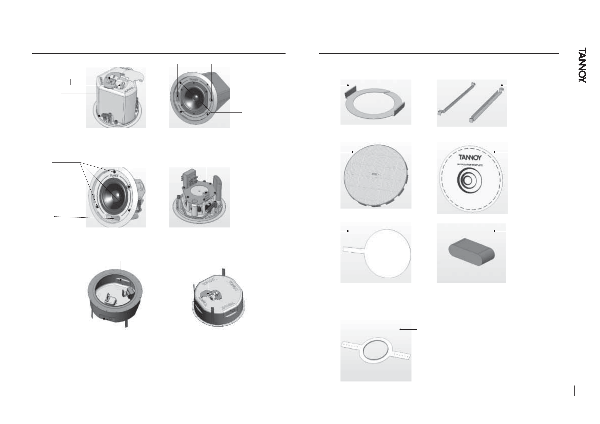
4. PRODUCT FEATURE IDENTIFICATION:
5. ACCESSORIES:
Conduit/Cable Clamp
Euro Type Connector
Mounting Wings
Fig 1.1: The blind-mount (BM) models come with a pre-fitted back-can
Screws for
mounting wings
Screws for
mounting wings
hctiwS yratoRtroP gninuT
rotcennoC epyT oruEhctiwS yratoR
Each product is supplied with the following accessories as standard:
C-Ring Tile bridge kit
Note: A tile bridge kit
must always be used
when installing into
suspended ceiling tiles
Grille Cut-out template
Tuning Port
Fig 1.2: A pre-install (PI) model shown without optional pre-install back-can
Safety Notice: In order to comply with UL regulations, the PI back-can must always be used with the CMS PI models.
Euro Type Plug
Conduit Knock-out points
Euro Type Connector
Fig 1.3: Optional pre-install (PI) back-can for PI models
Paint Mask
Optional accessories:
Foam port-plug
NOTE: Only supplied with PI
models for applications where
PI models are being installed
without back-cans. Do not use
the foam port-plug if you are
installing the PI product into a
back-can.
Plaster (Mud) Ring
Note that the 601 PI models have the transformer pre-attached to the inside of the 601 PI back-can, whereas the
501 models have the transformer pre-attached to the speaker assembly.
4
5
Page 4

CMS
6.1 MECHANICAL INSTALLATION GUIDE FOR SUSPENDED CEILINGS
6.2 MECHANICAL INSTALLATION GUIDE FOR SHEET-ROCK (PLASTER BOARD) CEILINGS
Remove the ceiling tile from its frame and place it on a flat surface. Mark the
1
cut-out area on the ceiling tile by tracing around the template provided.
Cut out the hole in the ceiling tile using a hole saw or pad saw.
2
Place the C-ring and tile-bridge on top of the ceiling panel, aligning the C-ring over the
3
hole, and screw the C-ring to the tile bridge using the fixings provided.
Mark the cut-out area on the ceiling by tracing around the template provided.
1
Cut out the hole in the ceiling using a hole saw or pad saw, then slide the
2
C-ring into the ceiling, aligning it over the cut-out hole).
Go to section 7 for wiring and set-up instructions then return to point 4 below.
3
Slide the speaker assembly through the hole and turn the screws on the front of the
4
speaker to extend the mounting wings. Tighten the screws until a firm grip is achieved.
If using a power driver, Tannoy recommends a torque setting of 1.5Nm.
DO NOT OVERTIGHTEN!
Slide the tile panel back into the suspended ceiling. The tile bridge ends will catch over
5
the railings, supporting the weight of the speaker.
Go to section 7 for instructions on wiring and set-up.
Slide the speaker assembly through the hole and turn the screws to extend the mounting
4
wings. Tighten the screws until a firm grip is achieved.
If using a power driver, Tannoy recommends a torque setting of 1.5Nm.
DO NOT OVERTIGHTEN!
Insert grille by pushing it onto the speaker.
5
6
7
Page 5

CMS
6.3 MECHANICAL INSTALLATION INSTRUCTIONS FOR OPTIONAL PLASTER RING:
6.4 INSTRUCTIONS FOR OPTIONAL PRE-INSTALLATION BACK-CAN (PI MODELS ONLY):
An optional plaster (mud) ring bracket is available from Tannoy. This bracket is designed to be pre-installed into newly
constructed, non-suspended ceilings.
Nail or screw the plaster ring to the joists.
1
Lay the speaker wiring to where the speaker will be fitted and complete the
2
plastering work on the ceiling.
Cut out the hole in the ceiling using a hole saw or pad saw.
3
AN OPTIONAL PRE-INSTALL BACK-CAN IS AVAILABLE FOR ALL PI (PRE-INSTALL) MODELS. THIS BACK-CAN IS DESIGNED TO
BE PRE-INSTALLED INTO NEWLY CONSTRUCTED, NON-SUSPENDED CEILINGS.
Note that the 601 PI models have the transformer pre-attached to the inside of the 601 PI back-can, whereas the 501 models have
the transformer pre-attached to the speaker assembly.
Attach the back-can to a safe and secure fixing point. This can be done in
1
a number of ways…
METHOD 1: Fix the back-can to a secure fixing point by using suitable
fixings with the 4 fixing holes provided on the PI back-can
METHOD 2: Secure the back-can to a safe and secure fixing point using
suitable fixings with the flexible straps that are attached to the PI back-can.
Go to section 7 for instructions on wiring then return to point 5 below.
4
Slide the speaker assembly through the hole and turn the screws to extend the mounting
5
wings. Tighten the screws until a firm grip is achieved.
DO NOT OVERTIGHTEN!
Insert grille by pushing it onto the speaker.
6
METHOD 3:
a. Attach the PI back-can to the optional pre-mount ring (plaster ring) using
the fixings provided with the pre-mount ring.
b. Next, secure the wings of the pre-mount ring to a safe and secure fixing
point by using suitable fixings.
8
(PTO)
9
Page 6

CMS
6.4 INSTRUCTIONS FOR OPTIONAL PRE-INSTALLATION BACK-CAN (PI MODELS ONLY):
2
Attach the conduit to the installed back-can. This can be attached in two ways:
a. You can use the clamp at the back of the pre-install
back-can. The product will accept a squeeze connector
with a thread size of up to 22mm: To remove the cable
clamp, simply unscrew the threaded washer (under the
wiring cover) which holds the cable clamp in place and
replace it with a conduit squeeze connector.
b. You can use any of the three knock-out points at the
sides of the PI back-can (19mm, 22mm or 28mm diameter):
Conduit
Conduit Squeeze
Connector
6.4 INSTRUCTIONS FOR OPTIONAL PRE-INSTALLATION BACK-CAN (PI MODELS ONLY):
Go to section 7 for instructions on wiring and setting up then return to point 5 below.
5
Slide the speaker assembly through the hole and turn the screws to extend
6
the mounting wings. Tighten the screws until a firm grip is achieved.
DO NOT OVERTIGHTEN!
3
If conduit is not chosen as the wiring method, run an approved speaker cable to the
installed can. Terminate in the top mounted cable clamp or with an approved cable
connector in one of the three knock-out points at the sides of the PI back-can.
.
Cut hole in proper location in ceiling material and installover pre installed back-can.
4
10
(PTO)
11
Page 7

CMS
7. WIRING AND SETTING UP:
8.1 CMS 501 MODEL DIMENSIONS:
Open the wiring cover at the back of the speaker can to access the Euro type connector
1
plug and socket.
For connection to an amplifier, use pins 1 and 2:
2
• Pin 1 is positive
• Pin 2 is negative
For connection to additional speakers in a distributed line,
pins 3 and 4 are in parallel where:
• Pin 3 is negative
• Pin 4 is positive
CMS 501 models TEMPLATE HOLE CUTOUT SIZE: 190mm
CMS 501 BM & CMS 501 DC BM:
189.5
[7.46"]
5.0
[0.20"]
181.3 [7.14"]
210.0 [8.27"]
CMS 501 PI & CMS 501 DC PI:
206.8
[8.14"]
Close the wiring cover and tighten both screws on the cable clamp. Use the rotary
3
switch located on the front of the unit to select whether you wish to use the speaker in
a low-impedance or distributed-line application.
THE SPEAKER IS SUPPLIED IN LOW IMPEDANCE MODE. NEVER CONNECT THE
SPEAKER TO A 70/100 VOLT AMPLIFIER WHILE IT IS SET FOR LOW IMPEDANCE.
All CMS 501 models use a 30W transformer. When using distributed-line systems, the
transformer can be tapped at 30W, 15W and 7.5W, with an additional 3.75W tapping
for 70.7V line systems.
All CMS 601 models use a 60W transformer. When using distributed-line systems, the
4
transformer can be tapped at 60W, 30W, and 15W, with an additional 7.5W tapping for
70.7V line systems.
CMS 501 PI BACK CAN:
5.0
[0.20"]
153.5
[6.04"]
135.6
[5.34"]
181.3 [7.14"]
210.0 [8.27"]
256.0
[10.08"]
136.2
[5.36"]
12
186.4
[7.34"]
288.0 [11.34"]
8.8
[0.35"]
13
Page 8

CMS
8.2 CMS 601 MODEL DIMENSIONS:
9. TECHNICAL SPECIFICATIONS:
CMS 601 models TEMPLATE HOLE CUTOUT SIZE: 253mm
CMS 601 BM & CMS 601 DC BM:
258.0
[10.16"]
5.0
[0.20"]
244.3 [9.62"]
280.0 [11.02"]
CMS 601 PI:
95.5
[3.76"]
5.0
[0.20"]
244.3 [9.62"]
280.0 [11.02"]
275.3
[10.84"]
(Watts, RMS)
(Watts, Peak)
1W @ 1m **
of Blind-Mount (BM) models ((3dB)
BM models (-10dB)
of Pre-Install (PI) models ((3dB)
PI models (-10dB)
Line voltage:
Inductive Tweeter cirtnecnoC lauDreteewT evitcudnIcirtnecnoC lauDserutaeF
Symmetrical
Constant Directivity
50 WPower Rating
100 WPower Rating
89 dBSensitivity (dB)
89 Hz -22 KHzFrequency Response*
73 HzLow frequency limit* of
85 Hz -22 KHzFrequency Response*
63 HzLow frequency limit* of
C Ring, tile bridge,
paint mask,
hole template, grille
Plaster (mud) ring gnir )dum( retsalPgnir )dum( retsalPgnir )dum( retsalPseirossecca lanoitpO
Security toggle clamp pmalc elggot ytiruceSpmalc elggot ytiruceSpmalc elggot ytiruceS:ngised gnipmalC
70V/ 100V /
Low Impedance (6 Ohms)
30 W/ 15 W/ 7.5 W
3.75 W (70V-line only)
LoZ
(6 Ohms)
OFF
OFF position
disconnects from line
CD106 SMC106SMCCD105 SMC105SMCLEDOM
Symmetrical
Constant Directivity
60 W 60 W 80 W
120 W 120 W 160 W
89 dB 91 dB 90 dB
88 Hz -54 KHz 75 Hz -20 KHz 63 Hz – 20 KHz
65 Hz 50 Hz 43 Hz
85 Hz -54 KHz 75 Hz -20 KHz 65 Hz – 20 KHz
63 Hz 50 Hz 50 Hz
paint mask,
hole template, grille
70V/ 100V /
Low Impedance (8 Ohms)
3.75 W (70V-line only)
LoZ
(8 Ohms)
OFF
disconnects from line
W 5.7 /W 51 /W 03detnuom tnorf ,hctiws yrator aiv sgnippaT
noitisop FFO:hctiwS
Symmetrical
Constant Directivity
,egdirb elit ,gniR Cseirossecca dedulcnI
C Ring, tile bridge,
paint mask,
hole template, grille
70V/ 100V /
Low Impedance (6 Ohms)
60 W/ 30 W/ 15 W
7.5 W (70V-line only)
LoZ
(6 Ohms)
OFF
OFF position
disconnects from line
Symmetrical
Constant Directivity
C Ring, tile bridge,
paint mask,
hole template, grille
70V/ 100V /
Low Impedance (8 Ohms)
60 W/ 30 W/ 15 W
7.5 W (70V-line only)
LoZ
(8 Ohms)
OFF
OFF position
disconnects from line
14
CMS 601DC PI
CMS 601 PI BACK-CAN:
5.0
[0.20"]
99.4
[3.91"]
168.5
[6.63"]
244.3 [9.62”]
280.0 [11.02’]
319.0
[12.56"]
249.4 [9.82"]
351.0 [13.82"]
151.2
[5.95"]
[0.35"]
8.8
front of tile surface to safety lug. BM
back of tile surface to safety lug PI can
* Measured in ceiling (2 half space)
** 1W @ 1m, 2.83V for 8
, 2.4V for 6
Complete with
Fixed back can
Separate PI back can nac kcab IP etarapeSnac kcab IP etarapeSnac kcab IP etarapeS)IP( llatsnI erP :noitpO
Cable clamp
plus up to 22mm
squeeze connector
3 sets of horizontal
positions, 19/22/28mm
diameters.
Loop through with
screw terminals
IN: 1+ve 2-ve
OUT: 3-ve 4+ve
190mm (7.5") BM & PI IP & MB )"0.01( mm352IP & MB )"0.01( mm352IP & MB )"5.7( mm091MB retemaid eloh gnilieC
190mm (7.5") BM & PI IP & MB )"0.01( mm352IP & MB )"0.01( mm352IP & MB )"5.7( mm091IP retemaid eloh gnilieC
210mm (8.2") )"0.11( mm082)"0.11( mm082)"2.8( mm012retemaiD lezeB
207mm (8.2")Max height:
154mm (6.1")Max height:
UL-1480, UL-2043, CE UL-1480, UL-2043, CEUL-1480, UL-2043, CEUL-1480, UL-2043, CE slavorppA
Fixed back can
plus up to 22mm
squeeze connector
positions, 19/22/28mm
diameters.
screw terminals
OUT: 3-ve 4+ve
207mm (8.2") 276mm (10.9") 276mm (10.9")
154mm (6.1") 169mm (6.7") 169mm (6.7")
htiw etelpmoC)MB( tnuoM dnilB :noitpO
pmalc elbaCsnoitpo elbaC
htiw hguorht pooLrotcennoC
ev-2 ev+1 :NItuo-nip yaw 4 rotcennoC
Complete with
Fixed back can
Cable clamp
plus up to 22mm
squeeze connector
latnoziroh fo stes 3snoitcennoc tuo-kconk tiudnoC
3 sets of horizontal
positions, 19/22/28mm
diameters.
Loop through with
screw terminals
IN: 1+ve 2-ve
OUT: 3-ve 4+ve
Complete with
Fixed back can
Cable clamp
plus up to 22mm
squeeze connector
3 sets of horizontal
positions, 19/22/28mm
diameters.
Loop through with
screw terminals
IN: 1+ve 2-ve
OUT: 3-ve 4+ve
15
Page 9

CMS
10. PAINTING
If desired, the grille and baffle panel may be painted to match the surrounding décor.
Painting the baffle:
Carefully mask off the driver assembly using the paint-mask provided to ensure that the paint does not come into
contact with the cone and roll surround.
Apply several thin coats of paint – this will provide a better finish than one overly thick coat.
Painting the grille:
Carefully remove the acoustically transparent foam from the reverse side of the grille.
Paint the grille and then replace the foam - several thin coats of paint will provide a better finish than one
overly thick coat.
Re-bond the foam to the grille over the entire area using a light spray-adhesive to avoid audible resonances.
11. WARRANTY
No maintenance of the CMS loudspeaker is necessary.
All Tannoy professional loudspeaker products are covered by a 5 year warranty from the date of manufacture
subject to the absence of misuse, overload or accidental damage. Claims will not be considered if the serial
number has been altered or removed. Work under warranty should only be carried out by a Tannoy Professional
dealer or service agent. This warranty in no way affects your statutory rights. For further information please
contact your dealer or distributor in your country. If you cannot locate your distributor please contact Customer
Services, Tannoy Ltd at the address given below.
Customer Services
Tannoy Ltd.
Rosehall Industrial Estate
Coatbridge
Strathclyde
ML5 4TF
Scotland
Tel: 01236 420199 (National)
+44 1236 420199 (International)
Fax: 01236 428230 (National)
+44 1236 428230 (International)
E-mail: enquiries@tannoy.com
12. DECLARATION OF CONFORMITY:
The following apparatus is manufactured in China for Tannoy
Ltd of Rosehall Industrial Estate, Coatbridge, Scotland, ML5 4TF
and conform(s) to the protection requirements of the European
Electromagnetic Compatibility Standards and Directives relevant
to Domestic Electrical Equipment. The apparatus is designed
and constructed such that electromagnetic disturbances generated
do not exceed levels allowing radio and telecommunications
equipment and other apparatus to operate as intended, and, the
apparatus has an adequate level of intrinsic immunity to
electromagnetic disturbance to enable operation as specified
and intended.
Details of the Apparatus: Tannoy Contractor Loudspeaker
Model Numbers: CMS 501 BM
CMS 501 DC BM
CMS 501 PI
CMS 501 DC PI
CMS 601 BM
CMS 601 DC BM
CMS 601 PI
CMS 601 DC PI
Applicable Standards: EN 50081-1 Emission
EN 50082-1 Immunity
Electrical Safety: EN 60065
Signed:
16
DO NOT SHIP ANY PRODUCT TO TANNOY WITHOUT PREVIOUS AUTHORISATION
Our policy commits us to incorporating improvements to our products through continuous research
and development. Please confirm current specifications for critical applications with your supplier.
Position: Engineering Director - Professional Products
Tannoy Professional
Date: 14/12/2005
For Tannoy Ltd
17
Page 10

CMS
NOTES
NOTES
18
19
 Loading...