


OWNER’S MANUAL |
|
Estd. |
1926 |

|
In combining the best of traditional crafts and the latest production and design skills Tannoy presents the Canterbury loudspeaker. |
|
The Canterbury embodies the Tannoy philosophy. Cabinets in selected hardwoods are hand finished and polished to a standard that |
|
is unsurpassed. |
|
The Canterbury 15 SE is a truly special loudspeaker made only to order with |
|
certification and personalised nameplate. The speaker uses the classic Alcomax |
|
3 version of the famous Tannoy Dual Concentric™ driver. This magnet system |
|
endows the Dual Concentric™ with an exceptional transient response and |
|
increased sensitivity. This high performance driver is installed in braced |
|
birch-ply cabinet with burr walnut veneers and solid walnut mouldings. Acrolink |
|
99.9999% (6N) high purity copper wiring is used throughout, together with |
|
specially selected crossover components, including Hovland capacitors. High |
|
frequency energy can be tailored through a high current gold-plated switch |
|
block with controls for both treble energy and roll off. Low frequency adjustment is through the Tannoy Variable Distributed Port |
|
System (VDPS). The specially designed twin-roll impregnated fabric surround used on the drive unit's cone, ensures midrange purity |
|
combined with tight, controlled bass. |
|
Tannoy - A Short History |
|
In the early days of broadcasting radio sets needed both low and high voltage DC power that had to be supplied by batteries. The lead |
|
acid batteries used in the radio sets of the time needed regular recharging. |
|
In London, in 1926, Guy R. Fountain perfected a new type of electrical rectifier with the aim of designing a charger more suitable for |
|
use in the house. His rectifier consisted of two dis-similar metals held in a special electrolyte solution. One metal was Tantalum and |
|
the other an alloy of Lead. So successful was this invention that Guy Fountain founded a British Company called Tannoy (a contraction |
|
of the words 'Tantalum' and 'Alloy'). Tannoy soon became internationally known and highly regarded in all aspects of sound reproduction. |
|
Moving coil loudspeakers with DC energised magnets began Tannoy's continued success in the field of loudspeaker technology. |
|
A discrete two-way loudspeaker system followed in 1933 and shortly after a range of microphones and loudspeakers capable of high |
|
power handling. |
|
Tannoy has always been at the front of the communications revolution, developing its own equipment and production technology. |
|
The company built a fund of knowledge and experience, that has proved invaluable in the development of loudspeakers for a truly wide |
|
range of applications. The now famous Tannoy Dual Concentric™ principle was created and developed under Guy Fountain's direction |
|
around 1950. It is highly regarded by music enthusiasts, and recording and broadcast studios because of its unique properties in faithfully |
|
reproducing sound to an unusually high quality standard. |
|
Guy Fountain retired from the company in 1974 but the Tannoy company continues his philosophy dedicated to the accurate and |
|
realistic reproduction of music for both enthusiasts and professionals around the world. |
|
The Tannoy Research and Development unit has further refined the innovative Dual Concentric™ principle. Using the latest design |
|
and material technologies, with sophisticated circuit techniques in crossover design, Tannoy has produced a loudspeaker system with |
|
superb reproductive capabilities and exceptionally wide dynamic range. |
2 |
Tannoy is now part of the TG Group, whose goal is to design, produce and distribute the best engineered, most recognised and respected |
brands of high performance audio products in the world. |

Unpacking Instructions
Unfasten the bottom of the carton. Fold the end leaves out of the way and remove the packing tray to reveal the plinth and bottom of the loudspeaker cabinet. Locate and remove accessories pack. Turn the carton and loudspeaker over so that the cabinet now stands on the floor inside the carton. Lift the carton upwards to reveal the loudspeaker.
Examine all pieces of packing material and inspect the carton for signs of external damage. If there is evidence of excessive damage to the packaging and resulting damage to the loudspeaker inform the carrier and supplier immediately. Always keep the packing in such circumstances for subsequent examination.
Tannoy strongly suggests that you store the complete packaging set for possible future use.
Initial Positioning
Locate the loudspeakers so that the favourite listening position is approximately 15° from the axes of the cabinets. The axes of both cabinets should intersect at a point slightly in front of the listening position. Remember that the proximity of the loudspeakers to walls and corners will affect the sound. Some experimentation will probably be needed to fine tune the stereo image depth and low frequency sound quality. Close-to-wall positions - and room corners more so - have the effect of increasing very low frequency sound energy. Reflective adjacent walls may upset the stereo image by causing unwanted reflections.
The loudspeakers are designed to be used at least 1m from any side wall or reflective surface and at least 0.5m away from a rear wall. Only in this position will their exceptional stereo image depth capabilities be realised.
When the optimum position for the loudspeakers has been determined, position the three metal cups, provided in the accessories pack, so that they sit under the three support cones, on the underside of the loudspeaker. These are positioned two at the front and one at the rear. This will give maximum stability, and enable your loudspeakers to provide their full dynamics and resolution of detail.
WARNING: this operation should be carried out by two people, to avoid the risk of personal injury, should the speaker slip or fall.
Amplifier Connections
Connect the loudspeakers to the amplifier using a high quality cable. Your dealer will be able to make recommendations. The terminals will accept either spade or banana plugs. If not bi-wiring fit the link wires from the accessories pack, as shown in figure 2.
Arrange the connections so that the right hand amplifier channel terminals are connected to the right hand loudspeaker as viewed from the listening position.
Correct polarity of the connections between the amplifier and speakers is essential. The positive terminal on the amplifier left channel, marked + (plus) or coloured red, must be connected to the positive terminal on the left loudspeaker. The negative terminal on the amplifier left channel, marked - (minus) or coloured black, must be connected to the negative terminal on the left loudspeaker.
Repeat this connection for the right speaker.
Good quality cables and tight, well-made connections are necessary to eliminate resistive losses and maintain the correct damping of the loudspeaker by the amplifier.
If the cables and connections have been made correctly as described above the loudspeakers will be automatically in phase with each other. However if phasing is felt to be incorrect (for example, diffuse stereo image, lack of bass) then apply the following test:
Place the loudspeakers side by side and play a monophonic signal from the amplifier, choosing the programme material with a strong bass content. If phasing is correct bass will be full and rich. If incorrect there will be very little bass due to cancellation effects. Incorrect phasing can be remedied by reversing the connecting leads to one loudspeaker (at either the amplifier or the loudspeaker terminals but not both).
Note: Be certain to ensure that the amplifier is switched off when connecting or disconnecting loudspeaker leads. Accidentally shorting the loudspeaker leads together can damage some amplifiers. Such damage is outside warranty provisions.
3
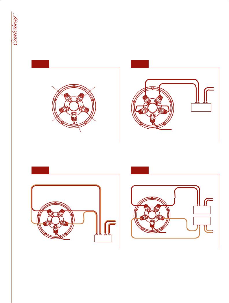
FIG. 1 TERMINAL PANEL CONNECTIONS |
FIG. 2 |
SINGLE WIRE MODE AND EARTH (GROUND) |
LEAD CONNECTION |
HIGH FREQUENCY
NEGATIVE(-) TERMINAL
- HF
LF
-
LOW FREQUENCY
NEGATIVE(-) TERMINAL
|
|
|
|
|
|
TO RIGHT |
HIGH FREQUENCY |
|
|
|
|
|
SPEAKER |
POSITIVE(+) TERMINAL |
|
|
|
|
|
|
HF+ |
HF |
HF+ |
|
|
|
|
|
- |
|
|
|
|
|
|
|
|
+ |
- |
+ |
- |
|
|
|
|
L |
|
R |
LF+ |
|
|
POWER AMPLIFIER |
|||
LF |
|
LF+ |
|
|
|
|
|
|
|
|
|
||
|
- |
|
|
|
|
|
LOW FREQUENCY |
|
|
|
|
|
|
POSITIVE(+) TERMINAL |
|
|
|
|
|
|
|
|
|
TO 'GROUND' OR |
|
|
|
|
|
|
'EARTH' CONNECTION |
|
|
|
'EARTH' OR 'GROUND' TERMINAL |
LINK WIRES IN PLACE |
ON AMPLIFIER (OPTIONAL) |
|
|
|
|
|
|
|
|
|
||
FIG. 3 |
BI-WIRE MODE AND EARTH (GROUND) |
LEAD CONNECTION |
- |
HF+ |
|
|
|
|
|
|
HF |
|
|
|
|
|
||
|
|
|
|
|
|
TO RIGHT |
|
|
|
|
|
|
|
SPEAKER |
|
LF |
|
LF+ |
|
|
|
|
|
- |
|
|
|
|
|
||
|
|
|
|
|
|
||
|
|
TO 'GROUND' OR |
+ |
- |
+ |
- |
|
|
|
|
L |
|
R |
||
|
|
'EARTH' CONNECTION |
POWER AMPLIFIER |
||||
LINK WIRES REMOVED |
ON AMPLIFIER (OPTIONAL) |
||||||
|
|
|
|
||||
|
|
|
|
|
|||
FIG. 4 |
BI-AMPING MODE AND EARTH (GROUND) |
LEAD CONNECTION |
|
|
|
TO RIGHT |
|
|
|
SPEAKER |
- |
HF+ |
|
|
HF |
|
|
|
|
|
+ L - |
+ R - |
|
|
HIGH FREQUENCY |
|
|
|
POWER AMPLIFIER |
|
|
LF+ |
LOW FREQUENCY |
|
LF |
POWER AMPLIFIER |
||
- |
+ L - |
+ R - |
|
|
|
||
|
|
TO 'GROUND' OR |
|
|
|
'EARTH' CONNECTION |
|
|
|
ON HIGH FREQUENCY |
TO RIGHT |
|
|
AMPLIFIER (OPTIONAL) |
|
|
|
|
SPEAKER |
LINK WIRES REMOVED |
|
|
|
4
 Loading...