

Page 1
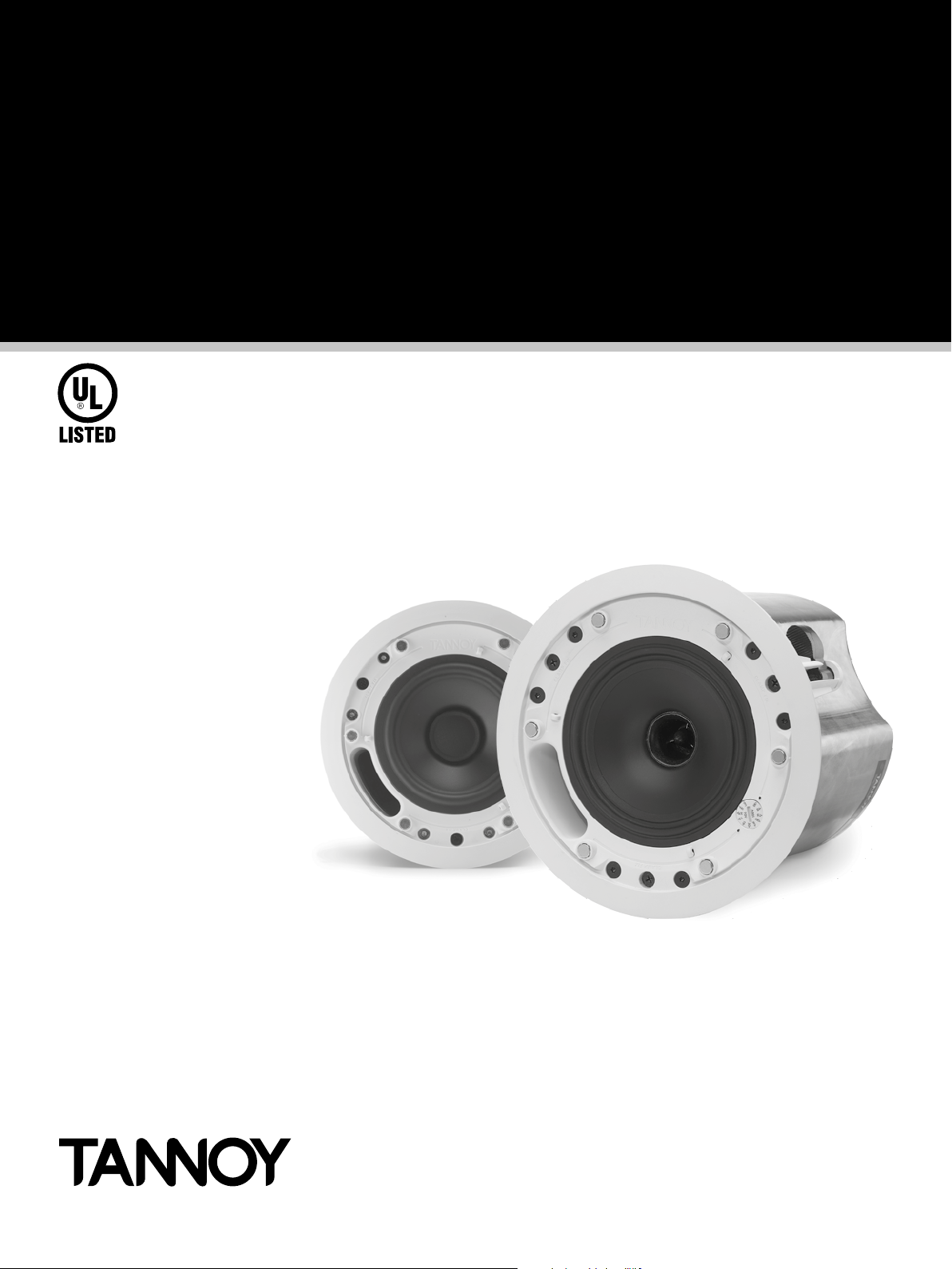
CMS 3.0 Series
In-Ceiling Loudspeakers
Operation Manual
Page 2

CMS 3.0 Series Operation Manual rev 3.0.0
2
Page 3

Table of Contents
Table of Contents
1. Introduction 4
2. Unpacking 4
3. Safety Notices 4
4. Product Feature Identication 5
4.1. Blind Mount ............................................................................................................................................5
4.2. Pre-install ...............................................................................................................................................5
4.3. Pre-install backcan .................................................................................................................................6
5. Accessories 7
6. Installation 8
6.1. Installation Guide for Suspended Ceilings ...............................................................................................8
6.2. Installation Guide for Sheetrock Ceilings .................................................................................................9
6.3. Installation Guide for Optional Plaster Ring ........................................................................................... 10
6.4. Installation Guide for Optional Pre-Installation Backcan (PI Models Only) .............................................. 11
7. Wiring and Setting Up 14
8. CMS Series Model Dimensions 15
9. Technical Specications 25
10. Painting 33
11. Warranty 34
12. Declaration of conformity 35
CMS 3.0 Series Operation Manual rev 3.0.0
3
Page 4

1. Introduction
1. Introduction
Thank you for purchasing this Tannoy Ceiling Monitor System product. Designed for both speech and music
program material, the Tannoy CMS range provides exceptional sonic quality and long-term reliability in all ceilingmount applications. The CMS 3.0 DC series features new 16 ohm Dual Concentric™ drivers for improved
performance and prolonged service life.
2. Unpacking
Every Tannoy product is carefully inspected before shipment. After unpacking, please inspect your product to
ensure no damage has occurred in transit. In the unlikely event of damage, please notify your dealer and retain
all shipping materials as your dealer may require return shipment.
All CMS loudspeakers are shipped in pairs and provided with the following accessories as standard: C-ring,
tile-bridge kit, cut-out template and paint mask. A plaster (mud) ring is available as an optional accessory.
3. Safety Notices
Some regional construction codes require the use of a secondary method of securing loudspeakers in the
ceiling to provide security of a back-up support. A secondary support line should be attached from the safety
loop on the rear of the product to a source point on the ceiling. For PI models, the secondary support line
should be attached from the back of the driver chassis to a source point on the ceiling. Please consult the
relevant construction codes in your region.
When using a power driver to install the product, it is essential to use the correct torque level settings to avoid
over-tightening and damage to the ceiling material or clamps. Recommended torque setting: 1.5 Nm
Tannoy will not be held responsible for any damages caused by the improper installation of these loudspeakers.
The CMS 603 ICT LS is UL-1480, category UUMW, for use with non-DC supervised systems.
Electrical Safety Notice: To comply with the standard UL-1480, metal-clad exible conduit (BX) is required for
connection to the terminal block for proper earth grounding.
In order to comply with UL regulations, the PI backcan must always be used with the CMS PI models.
SAFETY NOTE:
In order to comply with the relevant re safety regulations (ie. BS 5839:1998), it is required that in the event of
re, that failure of the circuit to which the loudspeaker is connected does not occur before evacuation of the
building is complete. Suitable measures include:
a) use of terminal blocks (for connection to primary) with a melting point of not less than 650°C, for example
constructed from ceramic materials;
b) use of terminal blocks of a lower melting point but protected with thermal insulation;
c) use of terminal blocks such that, on melting, an open-circuit or a short-circuit does not occur.
CMS 3.0 Series Operation Manual rev 3.0.0
4
Page 5
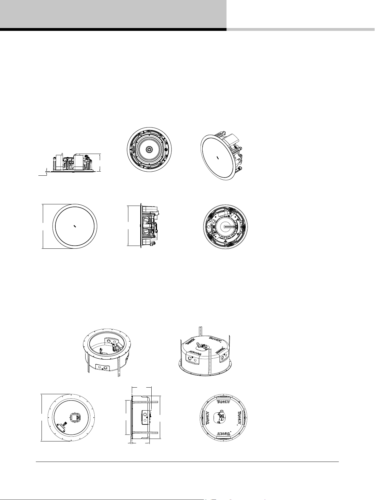
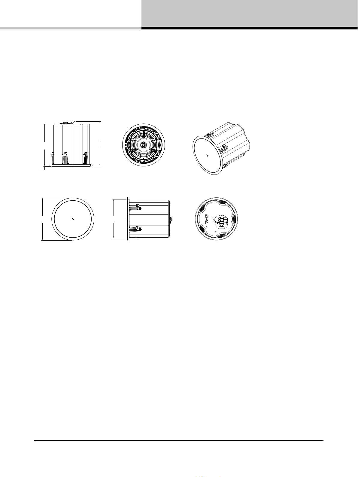
4. Product Feature Identification
4. Product Feature Identification
IMPORTANT NOTE: Drawings for each loudspeaker below are generic and apply to the loudspeaker types
specied. Some variations will be apparent in some models, but differences are not critical for installation
purposes except as noted.
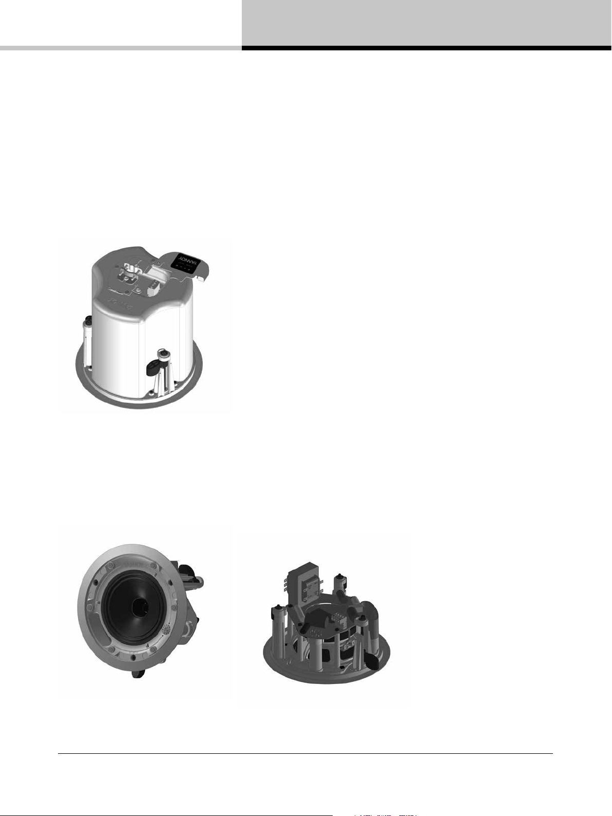
4.1. Blind Mount
The blind-mount models are supplied with a pre-tted backcan. Above applies to all models with a “BM” sufx
as well any others that do NOT have a “PI” sufx.
4.2. Pre-install
A pre-install (PI) unit is shown without the optional pre-install backcan.
CMS 3.0 Series Operation Manual rev 3.0.0
5
Page 6
4. Product Feature Identification
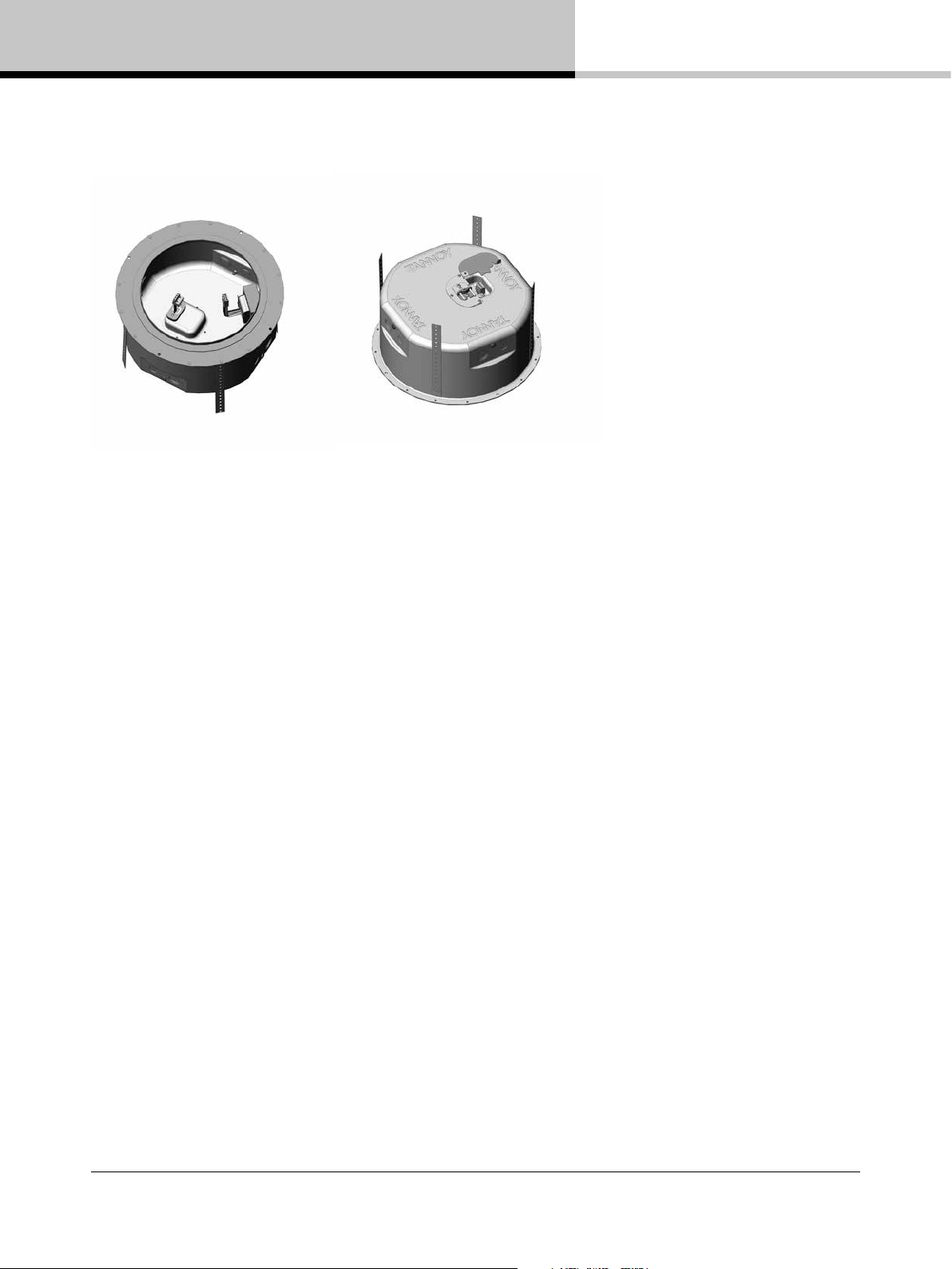
4.3. Pre-install backcan
Optional pre-install (PI) backcan for PI models.
NOTE: The CMS 603DC/ICT and CMS 803DC models have the transformer pre-attached to the inside of the
backcan. The CMS 503DC/ICT has the transformer pre-attached to the loudspeaker assembly.
CMS 3.0 Series Operation Manual rev 3.0.0
6
Page 7
5. Accessories
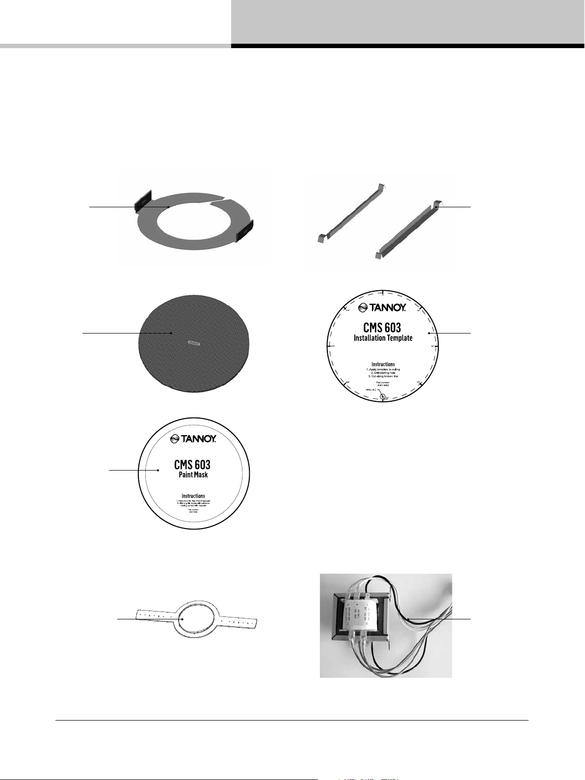
5. Accessories
Standard Accessories
C-Ring
Grille
Tile-bridge kit
Note: A tile-bridge kit
must always be used
when installing into
suspended ceiling tiles
Cut-out template
Paint Mask
Optional Accessories
Plaster (mud)
ring
60 W Transformer
Note: For use with CMS
803 PI in distributed lines
without backcans.
CMS 3.0 Series Operation Manual rev 3.0.0
7
Page 8
6. Installation
6. Installation
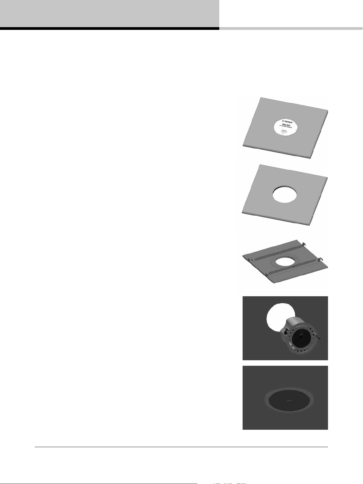
6.1. Installation Guide for Suspended Ceilings
1. Remove the ceiling tile from its frame and place it on a at
surface. Position the cutout template (self adhesive backed) on
the tile. (Fig.1)
2. Cut out the hole in the ceiling tile using a pad saw following
the broken line indicated on the template (Fig.2)
3. Place the C-Ring and tile-bridge on top of the ceiling panel,
aligning the C-Ring over the hole, and screw the C-Ring to the
tile bridge using the xings provided. (Fig.3)
Fig.1
4. Go to section 7 for instructions on wiring and set-up instructions.
5. Slide the speaker assembly through the hole. Turn the screws
(denoted “Screw Fix”) clockwise on the front of the speaker
to extend the mounting wings. Tighten the screws until a rm
grip is achieved. (NOTE: Screws have a PoziDriv head; use of a
PoziDriv driver is recommended). If using a power driver, Tannoy
recommends a torque setting of 1.5 Nm. (Fig.4)
DO NOT OVERTIGHTEN!
6. Attach the nylon safety to the hooks on the front bafe
before attaching the grille by presenting it to the speakers and
allowing the magnets to pull it into position (Fig.5). (With the
CMS 403DCe/ICTe, the grille is already tted to the product.)
NOTE ON INSTALLATION OF CMS 403DCe/ICTe:
Before tightening the screws in step 5, swivel the speaker in the
desired direction. When the screws are tightened, the speaker will
lock into position. Replace the front trim to conceal the mounting
screws.
Fig.2
Fig.3
Fig.4
CMS 3.0 Series Operation Manual rev 3.0.0
8
Fig.5
Page 9
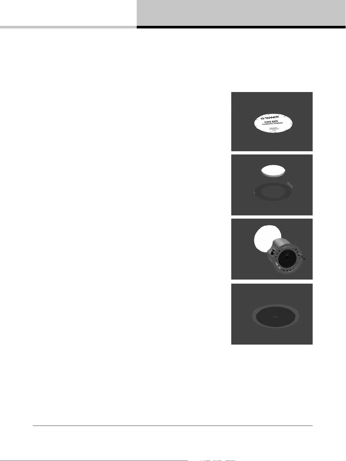
6.2. Installation Guide for Sheetrock Ceilings
1. Position the cutout template (self adhesive backed) on the
ceiling. (Fig.1)
2. Cut out the hole in the ceiling using a pad saw following the
broken line indicated on the template then slide the C-Ring into
the ceiling, aligning it over the cut-out hole. (Fig.2)
3. Go to section 7 for wiring and set-up instructions then return
to point 4 below.
4. Slide the speaker assembly through the hole. Turn the screws
(denoted “Screw Fix”) clockwise on the front of the speaker
to extend the mounting wings. Tighten the screws until a rm
grip is achieved. (NOTE: Screws have a PoziDriv head; use of a
PoziDriv driver is recommended). If using a power driver, Tannoy
recommends a torque setting of 1.5 Nm. (Fig.3)
6. Installation
Fig.1
Fig.2
DO NOT OVERTIGHTEN!
5. Attach the nylon safety to the hooks on the front bafe
before attaching the grille by presenting it to the speakers and
allowing the magnets to pull it into position (Fig.4). (With the
CMS 403DCe/ICTe, the grille is already tted to the product.)
NOTE ON INSTALLATION OF CMS 403DCe/ICTe:
Before tightening the screws in step 4, swivel the speaker in the
desired direction. When the screws are tightened, the speaker will
lock into position. Replace the front trim to conceal the mounting
screws.
Fig.3
Fig.4
CMS 3.0 Series Operation Manual rev 3.0.0
9
Page 10

6. Installation
6. Installation
6.3. Installation Guide for Optional Plaster Ring
An optional plaster (mud) ring bracket is available from Tannoy. This bracket is designed to be pre-installed
into newly constructed, non-suspended ceilings.
1. Nail or screw the plaster ring to the joists. (Fig.1)
2. Lay the speaker wiring to where the speaker will be tted and
complete the plastering work on the ceiling. (Fig.2)
3. Go to section 7 for instructions on wiring then return to point 4
below.
4. Slide the speaker assembly through the hole. Turn the screws
(denoted “Screw Fix”) clockwise on the front of the speaker
to extend the mounting wings. Tighten the screws until a rm
grip is achieved. (Note: Screws have a PoziDriv head; use of a
PoziDriv driver is recommended). If using a power driver, Tannoy
recommends a torque setting of 1.5 Nm. (Fig.3)
DO NOT OVERTIGHTEN!
5. Attach the nylon safety to the hooks on the front bafe
before attaching the grille by presenting it to the speakers and
allowing the magnets to pull it into position (Fig.4). (With the
CMS 403DCe/ICTe, the grille is already tted to the product.)
Fig.1
Fig.2
Fig.3
NOTE ON INSTALLATION OF CMS 403DCe/ICTe:
Before tightening the screws in step 4, swivel the speaker in the
desired direction. When the screws are tightened, the speaker
will lock into position.Replace the front trim to conceal the
mounting screws.
CMS 3.0 Series Operation Manual rev 3.0.0
10
Fig.4
Page 11
6. Installation
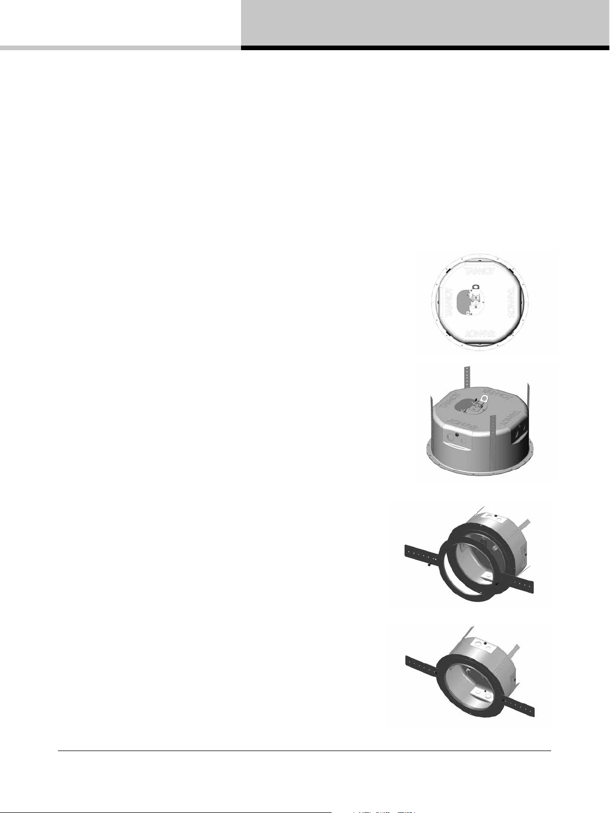
6.4. Installation Guide for Optional Pre-Installation Backcan (PI Models Only)
An optional pre-install backcan is available for all pre-install (PI) models. The backcan is designed for
pre-installation in newly constructed, non-suspended ceilings.
NOTE: The CMS 603DC/ICT and CMS 803DC models have the transformer pre-attached to the inside of the
backcan; the CMS 503DC/ICT models have the transformer pre-attached to the loudspeaker assembly.
1. Attach the backcan to a safe and secure xing point.
This can be done in a number of ways:
METHOD 1: Fix the backcan to a secure xing point by using
suitable xings with the 4 xing holes provided on the PI backcan.
(Fig.1)
Fig.1
METHOD 2: Secure the backcan to a safe and secure xing point
using suitable xings with the exible straps that are attached to
the PI backcan. (Fig.2)
METHOD 3:
a. Attach the PI backcan to the optional pre-mount ring (plaster
ring) using the xings provided with the pre-mount ring. (Fig.3)
b. Next, secure the wings of the pre-mount ring to a safe and
secure xing point by using suitable xings. (Fig.4)
Fig.2
Fig.3
Please turn over
CMS 3.0 Series Operation Manual rev 3.0.0
Fig.4
11
Page 12
6. Installation
6. Installation
6.4. Installation Guide for Optional Pre-Installation Backcan (PI Models Only)
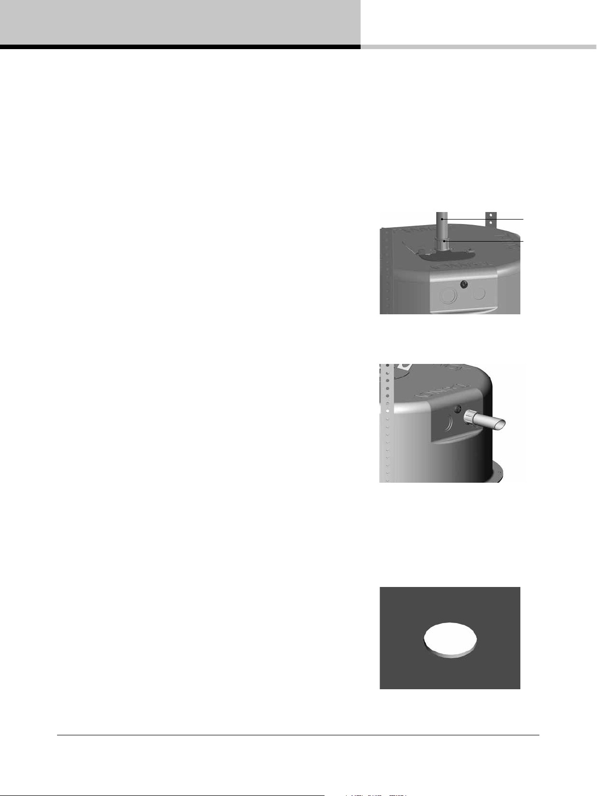
2. Attach the conduit to the installed backcan.
This can be done in two ways:
METHOD 1: You can use the clamp at the back of the pre-install
backcan. The product will accept a squeeze connector with a
thread size of up to 22 mm: To remove the cable clamp, simply
unscrew the threaded washer (under the wiring cover) which
holds the cable clamp in place and replace it with a conduit
squeeze connector. (Fig.5)
METHOD 2: You can use any of the three knock-out points at
the sides of the PI backcan (19 mm, 22 mm or 28 mm diameter).
(Fig.6)
Conduit
Conduit
Squeeze
Connector
Fig.5
Fig.5
Fig.6
3. If conduit is not chosen as the wiring method, run an
approved speaker cable to the installed can. Terminate in the top
mounted cable clamp or with an approved cable connector in
one of the three knock-out points at the sides of the PI backcan.
4. Cut hole in the proper location in the ceiling using a pad saw.
Place the pre-install backcan over the hole. (Fig.7)
CMS 3.0 Series Operation Manual rev 3.0.0
12
Fig.7
Page 13

6.4. Installation Guide for Optional Pre-Installation Backcan (PI Models Only)
5. Go to section 7 for instructions on wiring and setting up then
return to point 6 below.
6. Slide the speaker assembly through the hole. Turn the screws
(denoted “Screw Fix”) clockwise on the front of the speaker
to extend the mounting wings. Tighten the screws until a rm
grip is achieved. (NOTE: Screws have a PoziDriv head; use of a
PoziDriv driver is recommended). If using a power driver, Tannoy
recommends a torque setting of 1.5 Nm. (Fig.8)
6. Installation
Fig.8
DO NOT OVERTIGHTEN!
7. Attach the nylon safety to the hooks on the front bafe before
attaching the grille by presenting it to the speakers and allowing
the magnets to pull it into position. (Fig.9)
Fig.9
CMS 3.0 Series Operation Manual rev 3.0.0
13
Page 14

7. Wiring and Setting Up
7. Wiring and Setting Up
1. Open the wiring cover (if applicable) and locate the Euro-type
connector plug and socket at the back of the speaker. (Fig.1)
2. For connection to an amplier, use Pins 1 and 2 (Fig.2):
• Pin 1 is positive
• Pin 2 is negative
For connection to additional speakers in a distributed line,
Pins 3 and 4 are in parallel where:
• Pin 3 is negative
• Pin 4 is positive
3. Close the wiring cover and tighten both screws on the cable clamp
(if applicable).
Fig.1
4. Use the rotary switch on the front of the unit to select low
impedance (LoZ) mode or high impedance (70 V or 100 V) for
distributed applications.
THE SPEAKER IS SUPPLIED IN LOW IMPEDANCE MODE. NEVER
CONNECT THE SPEAKER TO A 70/100 VOLT AMPLIFIER WHILE IT
IS SET FOR LOW IMPEDANCE.
CMS 403DCe/ICTe and CMS 503DC/ICT models (all variants) use a
30 W transformer. In distributed line applications, the transformer can
be tapped at 30 W, 15 W and 7.5 W, with an additional 3.75 W tap
for 70 V line systems. (Fig.3)
CMS 603DC/ICT and CMS 803DC models (all variants) use a 60 W
transformer. In distributed line applications, the transformer can be
tapped at 60 W, 30 W and 15 W, with an additional 7.5 W tap for
70 V line systems. (Fig.4)
Fig.2
Fig.3
Fig.4
CMS 3.0 Series Operation Manual rev 3.0.0
14
Page 15

8. CMS Series Model Dimensions
CMS 403DCe
Hole Cut-out Size: 187 mm
147.6
[5.81"]
34.2
[1.35"]
8. CMS Series Model Dimensions
Ø205.0
[8.07"]
CMS 403ICTe
Hole Cut-out Size: 187 mm
147.6
[5.81"]
34.2
[1.35"]
Ø181.1
[7.13"]
Ø205.0
Ø181.1
[7.13"]
CMS 3.0 Series Operation Manual rev 3.0.0
15
Page 16

8. CMS Series Model Dimensions
8. CMS Series Model Dimensions
CMS 503DC BM
Hole Cut-out Size: 190 mm
188.0
[7.40"]
4.5
[0.18"]
205.9
[8.11"]
CMS 503ICT BM
Hole Cut-out Size: 190 mm
205.3
[8.08"]
181.3
[7.14"]
188.5
[7.42"]
4.2
[0.17"]
205.9
[8.11"]
CMS 3.0 Series Operation Manual rev 3.0.0
16
205.8
[8.10"]
181.3
[7.14"]
Page 17

8. CMS Series Model Dimensions
CMS 503DC LP
Hole Cut-out Size: 253 mm
98.6
[3.88"]
4.2
[0.17"]
8. CMS Series Model Dimensions
274.0
[10.79"]
CMS 503ICT LP
Hole Cut-out Size: 253 mm
98.6
[3.88"]
4.2
[0.17"]
244.3
[9.62"]
274.0
[10.79"]
244.3
[9.62"]
CMS 3.0 Series Operation Manual rev 3.0.0
17
Page 18

8. CMS Series Model Dimensions
8. CMS Series Model Dimensions
CMS 503DC PI
Hole Cut-out Size: 190 mm
133.3
[5.25"]
4.2
[0.17"]
205.9
[8.11"]
CMS 503ICT PI
Hole Cut-out Size: 190 mm
131.7
[5.19"]
4.2
[0.17"]
205.9
[8.11"]
CMS 3.0 Series Operation Manual rev 3.0.0
18
181.3
[7.14"]
Page 19

8. CMS Series Model Dimensions
CMS 503DC PI BACKCAN
Hole Cut-out Size: 190 mm
153.5
[6.04"]
8. CMS Series Model Dimensions
Ø288.0
[11.34"]
CMS 503ICT PI BACKCAN
Hole Cut-out Size: 190 mm
Ø186.4
[7.34"]
8.8
[0.35"]
136.2
[5.36"]
153.5
[6.04"]
Ø256.0
[10.08"]
Ø288.0
[11.34"]
Ø186.4
[7.34"]
8.8
[0.35"]
136.2
[5.36"]
Ø256.0
[10.08"]
CMS 3.0 Series Operation Manual rev 3.0.0
19
Page 20

8. CMS Series Model Dimensions
8. CMS Series Model Dimensions
CMS 603DC BM
Hole Cut-out Size: 253 mm
273.3
[10.76"]
4.2
[0.17"]
255.8
[10.07"]
274.0
[10.79"]
CMS 603ICT BM
Hole Cut-out Size: 253 mm
244.3
[9.62"]
256.5
[10.10"]
4.1
[0.16"]
274.0
[10.79"]
CMS 3.0 Series Operation Manual rev 3.0.0
20
273.8
[10.78"]
244.3
[9.62"]
Page 21

8. CMS Series Model Dimensions
CMS 603DC PI
Hole Cut-out Size: 253 mm
100.0
[3.94"]
4.1
[0.16"]
8. CMS Series Model Dimensions
274.0
[10.79"]
CMS 603ICT PI
Hole Cut-out Size: 253 mm
100.0
[3.94"]
4.1
[0.16"]
244.3
[9.62"]
273.5
[10.77"]
244.3
[9.62"]
CMS 3.0 Series Operation Manual rev 3.0.0
21
Page 22

8. CMS Series Model Dimensions
8. CMS Series Model Dimensions
CMS 603DC PI BACKCAN
Hole Cut-out Size: 253 mm
168.5
[6.63"]
Ø351.0
[13.82"]
CMS 603ICT PI BACKCAN
Hole Cut-out Size: 253 mm
Ø249.4
[9.82"]
8.8
[0.35"]
151.2
[5.95"]
168.5
[6.63"]
Ø319.0
[12.56"]
Ø351.0
[13.82"]
CMS 3.0 Series Operation Manual rev 3.0.0
22
Ø249.4
[9.82"]
8.8
[0.35"]
151.2
[5.95"]
Ø319.0
[12.56"]
Page 23

8. CMS Series Model Dimensions
CMS 603ICT LS
Hole Cut-out Size: 253 mm
8. CMS Series Model Dimensions
273.8
[10.78"]
4.1
[0.16"]
256.5
[10.10"]
274.0
[10.79"]
CMS 803DC BM
Hole Cut-out Size: 295 mm
244.3
[9.62"]
5.2
[0.20"]
319.0
[12.56"]
310.5
[12.22"]
327.7
[12.90"]
286.4
[11.27"]
CMS 3.0 Series Operation Manual rev 3.0.0
23
Page 24
8. CMS Series Model Dimensions
8. CMS Series Model Dimensions
CMS 803DC PI
Hole Cut-out Size: 295 mm
125.6
[4.94"]
5.2
[0.20"]
319.0
[12.56"]
CMS 803DC PI BACKCAN
Hole Cut-out Size: 295 mm
286.4
[11.27"]
168.5
[6.63"]
Ø397.0
[15.63"]
CMS 3.0 Series Operation Manual rev 3.0.0
24
[0.35"]
Ø291.4
[11.47"]
8.8
151.2
[5.95"]
Ø365.0
[14.37"]
Page 25
8. CMS Series Model Dimensions
CMS 803DCQ
Hole Cut-out Size: 295 mm
8. CMS Series Model Dimensions
5.2
[0.20"]
[12.56"]
[12.22"]
319.0
310.5
327.7
[12.90"]
286.4
[11.27"]
CMS 3.0 Series Operation Manual rev 3.0.0
25
Page 26
9. Technical Specifications
9. Technical Specifications
CMS 403DCe Model
Performance
Frequency response (-3 dB)
BM Backcan
Frequency range (-10 dB)
BM Backcan
System sensitivity (1 W @ 1 m)
Nominal Coverage Angle
Power Handling
Average 60 W
Programme 120 W
Peak 240 W
Recommended Amplier Power
Nominal Impedance (Lo, Z)
Rated maximum SPL
Average 106 dB
Peak 112 dB
Transformer Taps (via front rotary switch)
70 V
100 V
Transducers
Dual Concentric point source driver
Low Frequency
High Frequency
Physical
Enclosure
Backcan Reex loaded UL 94V-0 rated ABS
Bafe Reex loaded UL 94V-0 rated ABS
Grille Steel, with weather resistant coating
Safety Features
Clamping Design
Backcan
Blind Mount (BM) Complete with xed backcan
Connectors
Compliance
Dimensions
Bezel diameter
Front of ceiling to rear of pod
Hole cutout diameter
Net Weight (ea)
Included Accessories
Optional Accessories
Packed Quantity
(3)
(1)
(1)
(2)
110 Hz - 50 kHz
80 Hz - 54 kHz
88 dB (1 W = 4 V for 16 Ohms)
90 degrees conical
120 W @ 16 ohms
16 ohms
30 W (165 Ω) / 15 W (330 Ω) / 7.5 W (660 Ω) / 3.75 W (1320 Ω) /
OFF & low impedance operation
30 W (330 Ω) / 15 W (660 Ω) / 7.5 W (1320 Ω) /
OFF & low impedance operation
1 x 100 mm (4.0”) Dual Concentric driver, using Omnimagnet technology
35 mm (1.38”) voice coil, treated multi ber paper pulp cone
20 mm (0.79”) PEI dome
Safety ring located at rear of enclosure for load bearing safety bond
Min / Max clamping range: 0.0 mm (0.0”) /
20.0 mm (0.79”)
Recommended clamp torque: 1.5 Nm
Removable locking connector with screw terminals with
“loop through” facility
UL-1480, UL-2043, CE
205.0 mm (8.07”)
147.6 mm (5.81”)
187 mm (7.36”)
2.75 kg (6.06 lbs)
C-Ring, tile-bridge kit, paint mask, cut-out template, grille
Plaster (mud) ring
2
Orde ring In forma tion
Part N umber Colou r
8001 7410
CMS 40 3DCe Whit e /
Paintable
8001 4180
CMS 40 3e Zinc Pl ated
Plas ter (Mud) Ring Stee l
Notes:
1. Average ove r stated bandwidt h. Measured in
an IEC baf e in an Anechoic C hamber
2. Unweight ed pink noise inpu t, measured at
1 metre on a xis
3. Long term p ower handling cap acity as dened
in EIA - 426B test
A full ran ge of measuremen ts, performan ce data,
CLF and Ea se™ Data for CM S 403DCe can be
downloa ded from www.tann oypro.com.
Tannoy operat es a policy of contin uous research
and devel opment. The intro duction of new mater ials
or manuf acturing method s may introduce var iations
in actual p erformance; h owever, actual perfo rmance
always wil l equal or exceed th e published
speci cations, which Tanno y reserves the ri ght to
alter wit hout prior notic e. Please verif y the latest
specications when dealing with critical applications.
Copyrig ht (c) 2014 Tannoy Limited. A ll rights reser ved.
CMS 3.0 Series Operation Manual rev 3.0.0
26
Page 27

9. Technical Specifications
CMS 403ICTe Model
9. Technical Specifications
Performance
Frequency response (-3 dB)
Frequency range (-10 dB)
System sensitivity (1 W @ 1 m)
Nominal Coverage Angle
Coverage Angle (1 kHz to 6 kHz)
Directivity Factor (Q)
Directivity Index (DI)
Power Handling
Average 50 W
Programme 100 W
Peak 200 W
Recommended Amplier Power
Nominal Impedance (Lo, Z)
Rated maximum SPL
Average 105 dB
Peak 111 dB
Transformer Taps (via front rotary switch)
70 V
100 V
Crossover
Transducers
Low Frequency
High Frequency
Physical
Enclosure
Backcan Reex loaded UL 94V-0 rated ABS
Bafe Reex loaded UL 94V-0 rated ABS
Grille Steel, with weather resistant coating
Safety Features
Clamping Design
Connectors
Compliance
Dimensions
Bezel diameter
Front of ceiling to rear of pod
Hole cutout diameter
Net Weight (ea)
Included Accessories
Optional Accessories
Packed Quantity
(3)
(1)
(1)
(2)
110 Hz - 22 kHz
80 Hz - 24 kHz
88 dB (1 W = 4 V for 16 Ohms)
90 degrees conical
120 degrees
5.26 averaged 1 kHz to 6 kHz
6.30 averaged 1 kHz to 6 kHz
100 W @ 16 ohms
16 ohms
30 W (165 Ω) / 15 W (330 Ω) / 7.5 W (660 Ω) / 3.75 W (1320 Ω) /
OFF & low impedance operation
30 W (330 Ω) / 15 W (660 Ω) / 7.5 W (1320 Ω) /
OFF & low impedance operation
7 kHz inductively coupled
100 mm (4.00”) mineral loaded polypropylene
19 mm (0.75”) ICT aluminium dome
Safety ring located at rear of enclosure for load bearing safety bond
Min / Max clamping range: 0.0 mm (0.0”) /
20.0 mm (0.79”)
Recommended clamp torque: 1.5 Nm
Removable locking connector with screw terminals with
“loop through” facility
UL-1480, UL-2043, CE
205.0 mm (8.07”)
147.6 mm (5.81”)
187 mm (7.36”)
2.86 kg (6.31 lbs)
C-Ring, tile-bridge kit, paint mask, cut-out template, grille
Plaster (mud) ring
2
Orde ring In forma tion
Part N umber Colou r
8001 7760
CMS 40 3ICTe Whit e /
Paintable
8001 4180
CMS 40 3e Zinc Pl ated
Plas ter (Mud) Ring Stee l
Notes:
1. Average ove r stated bandwidt h. Measured in
an IEC baf e in an Anechoic C hamber
2. Unweight ed pink noise inpu t, measured at
1 metre on a xis
3. Long term p ower handling cap acity as dened
in EIA - 426B test
A full ran ge of measuremen ts, performan ce data,
CLF and Ea se™ Data for CM S 403ICTe can be
downloa ded from www.tann oypro.com.
Tannoy operat es a policy of contin uous research
and devel opment. The intro duction of new mater ials
or manuf acturing method s may introduce var iations
in actual p erformance; h owever, actual perfo rmance
always wil l equal or exceed th e published
speci cations, which Tanno y reserves the ri ght to
alter wit hout prior notic e. Please verif y the latest
specications when dealing with critical applications.
Copyrig ht (c) 2014 Tannoy Limited. A ll rights reser ved.
CMS 3.0 Series Operation Manual rev 3.0.0
27
Page 28

9. Technical Specifications
9. Technical Specifications
CMS 503DC Models
Performance
Frequency response (-3 dB)
BM Backcan
Frequency range (-10 dB)
BM Backcan
Frequency range (-10 dB)
PI Backcan
System sensitivity (1 W @ 1 m)
Nominal Coverage Angle
Power Handling
Average 60 W
Programme 120 W
Peak 240 W
Recommended Amplier Power
Nominal Impedance (Lo, Z)
Rated maximum SPL
Average 107 dB
Peak 113 dB
Transformer Taps (via front rotary switch)
70 V
100 V
Transducers
Dual Concentric point source driver
Low Frequency
High Frequency
Physical
Enclosure
Backcan Zinc plated steel
Bafe Reex loaded UL 94V-0 rated ABS
Grille Steel, with weather resistant coating
Safety Features
Clamping Design
Backcan Options
Blind Mount (BM) Complete with xed backcan
Pre Install (PI) Separate backcan for pre-installation
Cable Entry Options
Conduit Knockouts on PI Backcan
Connectors
Compliance
Dimensions
Bezel diameter
BM Model: Front of ceiling to rear of backcan
BM Model: Front of ceiling to top of safety loop
PI Model: Front of ceiling surface to rear of
speaker unit
PI Model: Front of accessory backcan bezel to
top of safety loop
Hole cutout diameter (all models)
Net Weight (ea)
CMS 503DC BM
CMS 503DC PI
PI Backcan
Included Accessories
Optional Accessories
Packed Quantity
(3)
(1)
(1)
(1)
(2)
85 Hz - 50 kHz
74 Hz - 54 kHz
70 Hz - 54 kHz
89 dB (1 W = 4 V for 16 Ohms)
90 degrees conical
120 W @ 16 ohms
16 ohms
30 W (165 Ω) / 15 W (330 Ω) / 7.5 W (660 Ω) / 3.75 W (1320 Ω) /
OFF & low impedance operation
30 W (330 Ω) / 15 W (660 Ω) / 7.5 W (1320 Ω) /
OFF & low impedance operation
1 x 130 mm (5.0”) Dual Concentric driver, using Omnimagnet technology
35 mm (1.38”) voice coil, treated multi ber paper pulp cone
20 mm (0.79”) PEI dome
Safety ring located at rear of enclosure for load bearing safety bond
Security toggle clamp
Min / Max clamping range 9.5 mm (0.37”) /
60 mm (2.36”)
Recommended clamp torque: 1.5 Nm
Cable clamp & squeeze connector for conduit up to 22 mm
3 Sets of horizontal positions 19 / 22 / 28 mm (0.75” / 0.87” / 1.10”)
Removable locking connector with screw terminals with
“loop through” facility
UL-1480, UL-2043, CE
205.9 mm (8.11”)
188.0 mm (7.40”)
205.3 mm (8.08”)
133.3 mm (5.25”)
153.5 mm (6.04”)
190 mm (7.48”)
4.1 kg (9.04 lbs)
3.1 kg (6.83 lbs)
2.6 kg (5.73 lbs)
C-Ring, tile-bridge kit, paint mask, cut-out template, grille
Plaster (mud) ring, Arco grille
2
Orde ring In forma tion
Part N umber Colou r
8001 7420
CMS 50 3DC BM Whit e /
Paintable
8001 7430
CMS 50 3DC PI Whit e /
Paintable
8001 4180
CMS 50 3 Zinc Pl ated
Plas ter (Mud) Ring Stee l
8001 7550
CMS 50 3 PI Backcan Zinc Pl ated
Steel
8001 7880
CMS 50 3 Arco G rille Whit e /
Paintable
UL-1480,
UL-2043
Notes:
1. Average ove r stated bandwidt h. Measured in
an IEC baf e in an Anechoic C hamber
2. Unweight ed pink noise inpu t, measured at
1 metre on a xis
3. Long term p ower handling cap acity as dened
in EIA - 426B test
A full ran ge of measuremen ts, performan ce data,
CLF and Ea se™ Data for CM S 503DC can be
downloa ded from www.tann oypro.com.
Tannoy operat es a policy of contin uous research
and devel opment. The intro duction of new mater ials
or manuf acturing method s may introduce var iations
in actual p erformance; h owever, actual perfo rmance
always wil l equal or exceed th e published
speci cations, which Tanno y reserves the ri ght to
alter wit hout prior notic e. Please verif y the latest
specications when dealing with critical applications.
Copyrig ht (c) 2014 Tannoy Limited. A ll rights reser ved.
CMS 3.0 Series Operation Manual rev 3.0.0
28
Page 29

9. Technical Specifications
CMS 503DC LP Model
9. Technical Specifications
Performance
Frequency response (-3 dB)
Frequency range (-10 dB)
System sensitivity (1 W @ 1 m)
Nominal Coverage Angle
Power Handling
Average 60 W
Programme 120 W
Peak 240 W
Recommended Amplier Power
Nominal Impedance (Lo, Z)
Rated maximum SPL
Average 107 dB
Peak 113 dB
Transformer Taps (via front rotary switch)
70 V
100 V
Transducers
Dual Concentric point source driver
Low Frequency
High Frequency
Physical
Enclosure
Backcan Zinc plated steel
Bafe Reex loaded UL 94V-0 rated ABS
Grille Steel, with weather resistant coating
Safety Features
Clamping Design
Cable Entry Options
Connectors
Compliance
Dimensions
Bezel diameter
Front of ceiling to rear of backcan
Hole cutout diameter
Net Weight (ea)
Included Accessories
Optional Accessories
Packed Quantity
(3)
(1)
(1)
(2)
88 Hz - 22 kHz
77 Hz - 24 kHz
89 dB (1 W = 4 V for 16 Ohms)
90 degrees conical
120 W @ 16 ohms
16 ohms
30 W (165 Ω) / 15 W (330 Ω) / 7.5 W (660 Ω) / 3.75 W (1320 Ω) /
OFF & low impedance operation
30 W (330 Ω) / 15 W (660 Ω) / 7.5 W (1320 Ω) /
OFF & low impedance operation
1 x 130 mm (5.0”) Dual Concentric driver, using Omnimagnet technology
35 mm (1.38”) voice coil, treated multi ber paper pulp cone
20 mm (0.79”) PEI dome
Safety ring located at rear of enclosure for load bearing safety bond
Security toggle clamp
Min / Max clamping range 9.5 mm (0.37”) /
60 mm (2.36”)
Recommended clamp torque: 1.5 Nm
Cable clamp & squeeze connector for conduit up to 22 mm
Removable locking connector with screw terminals with
“loop through” facility
UL-1480, UL-2043, CE
274.0 mm (10.79”)
98.6 mm (3.88”)
253.0 mm (9.96”)
3.3 kg (7.27 lbs)
C-Ring, tile-bridge kit, paint mask, cut-out template, grille
Plaster (mud) ring, Arco grille
2
Orde ring In forma tion
Part N umber Colou r
8001 7930
CMS 50 3DC LP Whit e /
Paintable
8001 7890
CMS 60 3 Arco G rille Whit e /
Paintable
Notes:
1. Average ove r stated bandwidt h. Measured in
an IEC baf e in an Anechoic C hamber
2. Unweight ed pink noise inpu t, measured at
1 metre on a xis
3. Long term p ower handling cap acity as dened
in EIA - 426B test
A full ran ge of measuremen ts, performan ce data,
CLF and Ea se™ Data for CM S 503DC LP can be
downloa ded from www.tann oypro.com.
Tannoy operat es a policy of contin uous research
and devel opment. The intro duction of new mater ials
or manuf acturing method s may introduce var iations
in actual p erformance; h owever, actual perfo rmance
always wil l equal or exceed th e published
speci cations, which Tanno y reserves the ri ght to
alter wit hout prior notic e. Please verif y the latest
specications when dealing with critical applications.
Copyrig ht (c) 2014 Tannoy Limited. A ll rights reser ved.
UL-1480,
UL-2043
CMS 3.0 Series Operation Manual rev 3.0.0
29
Page 30
9. Technical Specifications
9. Technical Specifications
CMS 503ICT Models
Performance
Frequency response (-3 dB)
BM Backcan
Frequency range (-10 dB)
BM Backcan
Frequency range (-10 dB)
PI Backcan
System sensitivity (1 W @ 1 m)
Nominal Coverage Angle
Coverage Angle (1 kHz to 6 kHz)
Directivity Factor (Q)
Directivity Index (DI)
Power Handling
Average 50 W
Programme 100 W
Peak 200 W
Recommended Amplier Power
Nominal Impedance (Lo, Z)
Rated maximum SPL
Average 106 dB
Peak 112 dB
Transformer Taps (via front rotary switch)
70 V
100 V
Crossover
Transducers
Low Frequency
High Frequency
Physical
Enclosure
Backcan Zinc plated steel
Bafe Reex loaded UL 94V-0 rated ABS
Grille Steel, with weather resistant coating
Safety Features
Clamping Design
Backcan Options
Blind Mount (BM) Complete with xed backcan
Pre Install (PI) Separate backcan for pre-installation
Cable Entry Options
Conduit Knockouts on PI Backcan
Connectors
Compliance
Dimensions
Bezel diameter
BM Model: Front of ceiling to rear of backcan
BM Model: Front of ceiling to top of safety loop
PI Model: Front of ceiling surface to rear of
speaker unit
PI Model: Front of accessory backcan bezel to
top of safety loop
Hole cutout diameter (all models)
Net Weight (ea)
CMS 503ICT BM
CMS 503ICT PI
PI Backcan
Included Accessories
Optional Accessories
Packed Quantity
(3)
(1)
(1)
(1)
(2)
85 Hz - 22 kHz
74 Hz - 24 kHz
71 Hz - 24 kHz
89 dB (1 W = 4 V for 16 Ohms)
90 degrees conical
105 degrees
5.6 averaged 1 kHz to 6 kHz
7.0 averaged 1 kHz to 6 kHz
100 W @ 16 ohms
16 ohms
30 W (165 Ω) / 15 W (330 Ω) / 7.5 W (660 Ω) / 3.75 W (1320 Ω) /
OFF & low impedance operation
30 W (330 Ω) / 15 W (660 Ω) / 7.5 W (1320 Ω) /
OFF & low impedance operation
7 kHz inductively coupled
130 mm (5.00”) mineral loaded polypropylene
ICT aluminium dome
Safety ring located at rear of enclosure for load bearing safety bond
Security toggle clamp
Min / Max clamping range 9.5 mm (0.37”) /
60 mm (2.36”)
Recommended clamp torque: 1.5 Nm
Cable clamp & squeeze connector for conduit up to 22 mm
3 Sets of horizontal positions 19 / 22 / 28 mm (0.75” / 0.87” / 1.10”)
Removable locking connector with screw terminals with
“loop through” facility
UL-1480, UL-2043, CE
205.9 mm (8.11”)
188.5 mm (7.42”)
205.8 mm (8.10”)
131.7 mm (5.19”)
153.5 mm (6.04”)
190 mm (7.48”)
3.85 kg (8.49 lbs)
2.85 kg (6.28 lbs)
2.6 kg (5.73 lbs)
C-Ring, tile-bridge kit, paint mask, cut-out template, grille
Plaster (mud) ring, Arco grille
2
Orde ring In forma tion
Part N umber Colou r
8001 7500
CMS 50 3ICT BM Whit e /
Paintable
800 1 7510
CMS 50 3ICT PI Whit e /
Paintable
8001 4180
CMS 50 3 Zinc Pl ated
Plas ter (Mud) Ring Stee l
8001 7550
CMS 50 3 PI Backcan Zinc Pl ated
Steel
8001 7880
CMS 50 3 Arco G rille Whit e /
Paintable
UL-1480,
UL-2043
Notes:
1. Average ove r stated bandwidt h. Measured in
an IEC baf e in an Anechoic C hamber
2. Unweight ed pink noise inpu t, measured at
1 metre on a xis
3. Long term p ower handling cap acity as dened
in EIA - 426B test
A full ran ge of measuremen ts, performan ce data,
CLF and Ea se™ Data for CM S 503ICT can be
downloa ded from www.tann oypro.com.
Tannoy operat es a policy of contin uous research
and devel opment. The intro duction of new mater ials
or manuf acturing method s may introduce var iations
in actual p erformance; h owever, actual perfo rmance
always wil l equal or exceed th e published
speci cations, which Tanno y reserves the ri ght to
alter wit hout prior notic e. Please verif y the latest
specications when dealing with critical applications.
Copyrig ht (c) 2014 Tannoy Limited. A ll rights reser ved.
CMS 3.0 Series Operation Manual rev 3.0.0
30
Page 31
9. Technical Specifications
CMS 503ICT LP Model
9. Technical Specifications
Performance
Frequency response (-3 dB)
Frequency range (-10 dB)
System sensitivity (1 W @ 1 m)
Nominal Coverage Angle
Power Handling
Average 50 W
Programme 100 W
Peak 200 W
Recommended Amplier Power
Nominal Impedance (Lo, Z)
Rated maximum SPL
Average 106 dB
Peak 112 dB
Transformer Taps (via front rotary switch)
70 V
100 V
Transducers
Low Frequency
High Frequency
Physical
Enclosure
Backcan Zinc plated steel
Bafe Reex loaded UL 94V-0 rated ABS
Grille Steel, with weather resistant coating
Safety Features
Clamping Design
Cable Entry Options
Connectors
Compliance
Dimensions
Bezel diameter
Front of ceiling to rear of backcan
Hole cutout diameter
Net Weight (ea)
Included Accessories
Optional Accessories
Packed Quantity
(3)
(1)
(1)
(2)
88 Hz - 50 kHz
77 Hz - 54 kHz
89 dB (1 W = 4 V for 16 Ohms)
90 degrees conical
100 W @ 16 ohms
16 ohms
30 W (165 Ω) / 15 W (330 Ω) / 7.5 W (660 Ω) / 3.75 W (1320 Ω) /
OFF & low impedance operation
30 W (330 Ω) / 15 W (660 Ω) / 7.5 W (1320 Ω) /
OFF & low impedance operation
1 x 130 mm (5.0”) mineral loaded polypropylene
ICT
Safety ring located at rear of enclosure for load bearing safety bond
Security toggle clamp
Min / Max clamping range 9.5 mm (0.37”) /
60 mm (2.36”)
Recommended clamp torque: 1.5 Nm
Cable clamp & squeeze connector for conduit up to 22 mm
Removable locking connector with screw terminals with
“loop through” facility
UL-1480, UL-2043, CE
274.0 mm (10.79”)
98.6 mm (3.88”)
253.0 mm (9.96”)
3.1 kg (6.83 lbs)
C-Ring, tile-bridge kit, paint mask, cut-out template, grille
Plaster (mud) ring, Arco grille
2
Orde ring In forma tion
Part N umber Colou r
8001 7940
CMS 50 3ICT LP Whit e /
Paintable
8001 7890
CMS 60 3 Arco G rille Whit e /
Paintable
Notes:
1. Average ove r stated bandwidt h. Measured in
an IEC baf e in an Anechoic C hamber
2. Unweight ed pink noise inpu t, measured at
1 metre on a xis
3. Long term p ower handling cap acity as dened
in EIA - 426B test
A full ran ge of measuremen ts, performan ce data,
CLF and Ea se™ Data for CM S 503ICT LP can be
downloa ded from www.tann oypro.com.
Tannoy operat es a policy of contin uous research
and devel opment. The intro duction of new mater ials
or manuf acturing method s may introduce var iations
in actual p erformance; h owever, actual perfo rmance
always wil l equal or exceed th e published
speci cations, which Tanno y reserves the ri ght to
alter wit hout prior notic e. Please verif y the latest
specications when dealing with critical applications.
Copyrig ht (c) 2014 Tannoy Limited. A ll rights reser ved.
UL-1480,
UL-2043
CMS 3.0 Series Operation Manual rev 3.0.0
31
Page 32

9. Technical Specifications
9. Technical Specifications
CMS 603DC Models
Performance
Frequency response (-3 dB)
BM Backcan
Frequency range (-10 dB)
BM Backcan
Frequency range (-10 dB)
PI Backcan
System sensitivity (1 W @ 1 m)
Nominal Coverage Angle
Power Handling
Average 80 W
Programme 160 W
Peak 320 W
Recommended Amplier Power
Nominal Impedance (Lo, Z)
Rated maximum SPL
Average 110 dB
Peak 116 dB
Transformer Taps (via front rotary switch)
70 V
100 V
Transducers
Dual Concentric point source driver
Low Frequency
High Frequency
Physical
Enclosure
Backcan Zinc plated steel
Bafe Reex loaded UL 94V-0 rated ABS
Grille Steel, with weather resistant coating
Safety Features
Clamping Design
Backcan Options
Blind Mount (BM) Complete with xed backcan
Pre Install (PI) Separate backcan for pre-installation
Cable Entry Options
Conduit Knockouts on PI Backcan
Connectors
Compliance
Dimensions
Bezel diameter
BM Model: Front of ceiling to rear of backcan
BM Model: Front of ceiling to top of safety loop
PI Model: Front of ceiling surface to rear of
speaker unit
PI Model: Front of accessory backcan bezel to
top of safety loop
Hole cutout diameter (all models)
Net Weight (ea)
CMS 603DC BM
CMS 603DC PI
PI Backcan
Included Accessories
Optional Accessories
Packed Quantity
(3)
(1)
(1)
(1)
(2)
75 Hz - 30 kHz
50 Hz - 30 kHz
46 Hz - 30 kHz
91 dB (1 W = 4 V for 16 Ohms)
90 degrees conical
160 W @ 16 ohms
16 ohms
60 W (83 Ω) / 30 W (165 Ω) / 15 W (330 Ω) / 7.5 W (660 Ω) /
OFF & low impedance operation
60 W (165 Ω) / 30 W (330 Ω) / 15 W (660 Ω) /
OFF & low impedance operation
1 x 165 mm (6.5”) Dual Concentric driver, using Omnimagnet technology
44 mm (1.75”) voice coil, treated multi ber paper pulp cone
25 mm (1.00”) PEI dome
Safety ring located at rear of enclosure for load bearing safety bond
Security toggle clamp
Min / Max clamping range 9.5 mm (0.37”) /
60 mm (2.36”)
Recommended clamp torque: 1.5 Nm
Cable clamp & squeeze connector for conduit up to 22 mm
3 Sets of horizontal positions 19 / 22 / 28 mm (0.75” / 0.87” / 1.10”)
Removable locking connector with screw terminals with
“loop through” facility
UL-1480, UL-2043, CE
274.0 mm (10.79”)
255.8 mm (10.07”)
273.3 mm (10.76”)
100.7 mm (3.96”)
168.5 mm (6.60”)
253 mm (9.96”)
6.6 kg (14.56 lbs)
3.65 kg (8.05 lbs)
3.68 kg (8.11 lbs)
C-Ring, tile-bridge kit, paint mask, cut-out template, grille
Plaster (mud) ring, Arco grille
2
Orde ring In forma tion
Part N umber Colou r
8001 7440
CMS 60 3DC BM Whit e /
Paintable
8001 7450
CMS 60 3DC PI Whit e /
Paintable
8001 4181
CMS 60 3 Zinc Pl ated
Plas ter (Mud) Ring Stee l
8001 7560
CMS 60 3 PI Backc an Zinc Pl ated
Steel
8001 7890
CMS 60 3 Arco G rille Whit e /
Paintable
UL-1480,
UL-2043
Notes:
1. Average ove r stated bandwidt h. Measured in
an IEC baf e in an Anechoic C hamber
2. Unweight ed pink noise inpu t, measured at
1 metre on a xis
3. Long term p ower handling cap acity as dened
in EIA - 426B test
A full ran ge of measuremen ts, performan ce data,
CLF and Ea se™ Data for CM S 603DC can be
downloa ded from www.tann oypro.com.
Tannoy operat es a policy of contin uous research
and devel opment. The intro duction of new mater ials
or manuf acturing method s may introduce var iations
in actual p erformance; h owever, actual perfo rmance
always wil l equal or exceed th e published
speci cations, which Tanno y reserves the ri ght to
alter wit hout prior notic e. Please verif y the latest
specications when dealing with critical applications.
Copyrig ht (c) 2014 Tannoy Limited. A ll rights reser ved.
CMS 3.0 Series Operation Manual rev 3.0.0
32
Page 33

9. Technical Specifications
CMS 603ICT Models
9. Technical Specifications
Performance
Frequency response (-3 dB)
BM Backcan
Frequency range (-10 dB)
BM Backcan
Frequency range (-10 dB)
PI Backcan
System sensitivity (1 W @ 1 m)
Nominal Coverage Angle
Coverage Angle (1 kHz to 6 kHz)
Directivity Factor (Q)
Directivity Index (DI)
Power Handling
Average 60 W
Programme 120 W
Peak 240 W
Recommended Amplier Power
Nominal Impedance (Lo, Z)
Rated maximum SPL
Average 109 dB
Peak 115 dB
Transformer Taps (via front rotary switch)
70 V
100 V
Crossover
Transducers
Low Frequency
High Frequency
Physical
Enclosure
Backcan Zinc plated steel
Bafe Reex loaded UL 94V-0 rated ABS
Grille Steel, with weather resistant coating
Safety Features
Clamping Design
Backcan Options
Blind Mount (BM) Complete with xed backcan
Pre Install (PI) Separate backcan for pre-installation
Cable Entry Options
Conduit Knockouts on PI Backcan
Connectors
Compliance
Dimensions
Bezel diameter
BM Model: Front of ceiling to rear of backcan
BM Model: Front of ceiling to top of safety loop
PI Model: Front of ceiling surface to rear of
speaker unit
PI Model: Front of accessory backcan bezel to
top of safety loop
Hole cutout diameter (all models)
Net Weight (ea)
CMS 603ICT BM
CMS 603ICT PI
PI Backcan
Included Accessories
Optional Accessories
Packed Quantity
(3)
(1)
(1)
(1)
(2)
78 Hz - 22 kHz
51 Hz - 24 kHz
46 Hz - 24 kHz
91 dB (1 W = 4 V for 16 Ohms)
90 degrees conical
92 degrees
7.1 averaged 1 kHz to 6 kHz
7.9 averaged 1 kHz to 6 kHz
120 W @ 16 ohms
16 ohms
60 W (83 Ω) / 30 W (165 Ω) / 15 W (330 Ω) / 7.5 W (660 Ω) /
OFF & low impedance operation
60 W (165 Ω) / 30 W (330 Ω) / 15 W (660 Ω) /
OFF & low impedance operation
7 kHz inductively coupled
165 mm (6.50”) mineral loaded polypropylene
ICT aluminium dome
Safety ring located at rear of enclosure for load bearing safety bond
Security toggle clamp
Min / Max clamping range 9.5 mm (0.37”) /
60 mm (2.36”)
Recommended clamp torque: 1.5 Nm
Cable clamp & squeeze connector for conduit up to 22 mm
3 Sets of horizontal positions 19 / 22 / 28 mm (0.75” / 0.87” / 1.10”)
Removable locking connector with screw terminals with
“loop through” facility
UL-1480, UL-2043, CE
274.0 mm (10.79”)
256.5 mm (10.10”)
273.8 mm (10.78”)
100.0 mm (3.94”)
168.5 mm (6.60”)
253 mm (9.96”)
TBA
TBA
3.68 kg (8.11 lbs)
C-Ring, tile-bridge kit, paint mask, cut-out template, grille
Plaster (mud) ring, Arco grille
2
Orde ring In forma tion
Part N umber Colou r
8001 7520
CMS 60 3ICT BM Whit e /
Paintable
8001 7530
CMS 60 3ICT PI Whit e /
Paintable
8001 4181
CMS 60 3 Zinc Pl ated
Plas ter (Mud) Ring Stee l
8001 7560
CMS 60 3 PI Backc an Zinc Pl ated
Steel
8001 7890
CMS 60 3 Arco G rille Whit e /
Paintable
UL-1480,
UL-2043
Notes:
1. Average ove r stated bandwidt h. Measured in
an IEC baf e in an Anechoic C hamber
2. Unweight ed pink noise inpu t, measured at
1 metre on a xis
3. Long term p ower handling cap acity as dened
in EIA - 426B test
A full ran ge of measuremen ts, performan ce data,
CLF and Ea se™ Data for CM S 603ICT can be
downloa ded from www.tann oypro.com.
Tannoy operat es a policy of contin uous research
and devel opment. The intro duction of new mater ials
or manuf acturing method s may introduce var iations
in actual p erformance; h owever, actual perfo rmance
always wil l equal or exceed th e published
speci cations, which Tanno y reserves the ri ght to
alter wit hout prior notic e. Please verif y the latest
specications when dealing with critical applications.
Copyrig ht (c) 2014 Tannoy Limited. A ll rights reser ved.
CMS 3.0 Series Operation Manual rev 3.0.0
33
Page 34

9. Technical Specifications
9. Technical Specifications
CMS 803DC Models
Performance
Frequency response (-3 dB)
BM Backcan
Frequency range (-10 dB)
BM Backcan
Frequency range (-10 dB)
PI Backcan
System sensitivity (1 W @ 1 m)
Nominal Coverage Angle
Power Handling
Average 90 W
Programme 180 W
Peak 360 W
Recommended Amplier Power
Nominal Impedance (Lo, Z)
Rated maximum SPL
Average 112 dB
Peak 118 dB
With THP60 - Average 110 dB
Transformer Taps (via front rotary switch)
70 V
100 V
Transducers
Dual Concentric point source driver
Low Frequency
High Frequency
Physical
Enclosure
Backcan Zinc plated steel
Bafe Reex loaded UL 94V-0 rated ABS
Grille Steel, with weather resistant coating
Safety Features
Clamping Design
Backcan Options
Blind Mount (BM) Complete with xed backcan
Pre Install (PI) Separate backcan for pre-installation
Cable Entry Options
Conduit Knockouts on PI Backcan
Connectors
Compliance
Dimensions
Bezel diameter
BM Model: Front of ceiling to rear of backcan
BM Model: Front of ceiling to top of safety loop
PI Model: Front of ceiling surface to rear of
speaker unit
PI Model: Front of accessory backcan bezel to
top of safety loop
Hole cutout diameter (all models)
Net Weight (ea)
CMS 803DC BM
CMS 803DC PI
PI Backcan
Included Accessories
Optional Accessories
Packed Quantity
(3)
(1)
(1)
(1)
(2)
47 Hz - 30 kHz
40 Hz - 35 kHz
41 Hz - 35 kHz
92 dB (1 W = 4 V for 16 Ohms)
90 degrees conical
180 W @ 16 ohms
16 ohms
60 W (83 Ω) / 30 W (165 Ω) / 15 W (330 Ω) / 7.5 W (660 Ω) /
OFF & low impedance operation
60 W (165 Ω) / 30 W (330 Ω) / 15 W (660 Ω) /
OFF & low impedance operation
1 x 200 mm (8.0”) Dual Concentric driver, using Omnimagnet technology
44 mm (1.75”) voice coil, treated multi ber paper pulp cone
25 mm (1.00”) PEI dome
Safety ring located at rear of enclosure for load bearing safety bond
Security toggle clamp
Min / Max clamping range 9.5 mm (0.37”) /
60 mm (2.36”)
Recommended clamp torque: 1.5 Nm
Cable clamp & squeeze connector for conduit up to 22 mm
3 Sets of horizontal positions 19 / 22 / 28 mm (0.75” / 0.87” / 1.10”)
Removable locking connector with screw terminals with
“loop through” facility
UL-1480, UL-2043, CE
319.0 mm (12.56”)
310.5 mm (12.22”)
327.7 mm (12.90”)
125.6 mm (4.94”)
168.5 mm (6.63”)
295 mm (11.61”)
8.5 kg (18.74 lbs)
4.9 kg (10.80 lbs)
4.0 kg (8.81 lbs)
C-Ring, tile-bridge kit, paint mask, cut-out template, grille
Plaster (mud) ring, Arco grille
2
Orde ring In forma tion
Part N umber Colou r
8001 7470
CMS 80 3DC BM Whit e /
Paintable
8001 7480
CMS 80 3DC PI Whit e /
Paintable
8001 4650
CMS 80 3 Zinc Pl ated
Plas ter (Mud) Ring Stee l
8001 7570
CMS 80 3 PI Backc an Zinc Pl ated
Steel
8001 7900
CMS 80 3 Arco G rille Whit e /
Paintable
UL-1480,
UL-2043
Notes:
1. Average ove r stated bandwidt h. Measured in
an IEC baf e in an Anechoic C hamber
2. Unweight ed pink noise inpu t, measured at
1 metre on a xis
3. Long term p ower handling cap acity as dened
in EIA - 426B test
A full ran ge of measuremen ts, performan ce data,
CLF and Ea se™ Data for CM S 803DC can be
downloa ded from www.tann oypro.com.
Tannoy operat es a policy of contin uous research
and devel opment. The intro duction of new mater ials
or manuf acturing method s may introduce var iations
in actual p erformance; h owever, actual perfo rmance
always wil l equal or exceed th e published
speci cations, which Tanno y reserves the ri ght to
alter wit hout prior notic e. Please verif y the latest
specications when dealing with critical applications.
Copyrig ht (c) 2014 Tannoy Limited. A ll rights reser ved.
CMS 3.0 Series Operation Manual rev 3.0.0
34
Page 35

9. Technical Specifications
CMS 803DCQ Model
9. Technical Specifications
Performance
Frequency response (-3 dB)
Frequency range (-10 dB)
BM Backcan
Frequency range (-10 dB)
PI Backcan
System sensitivity (1 W @ 1 m)
Nominal Coverage Angle
Power Handling
Average 90 W
Programme 180 W
Peak 360 W
Recommended Amplier Power
Nominal Impedance (Lo, Z)
Rated maximum SPL
Average 113 dB
Peak 119 dB
With THP60 - Average 111 dB
Transformer Taps (via front rotary switch)
70 V
100 V
Transducers
Dual Concentric point source driver
Low Frequency
High Frequency
Physical
Enclosure
Backcan Zinc plated steel
Bafe Reex loaded UL 94V-0 rated ABS
Grille Steel, with weather resistant coating
Safety Features
Clamping Design
Cable Entry Options
Connectors
Compliance
Dimensions
Bezel diameter
Front of ceiling to rear of backcan
Front of ceiling to top of safety loop
Hole cutout diameter (all models)
Net Weight (ea)
Included Accessories
Optional Accessories
Packed Quantity
(3)
(1)
(1)
(1)
(2)
47 Hz - 30 kHz
40 Hz - 35 kHz
41 Hz - 35 kHz
93 dB (1 W = 4 V for 16 Ohms)
60 degrees conical
180 W @ 16 ohms
16 ohms
60 W (83 Ω) / 30 W (165 Ω) / 15 W (330 Ω) / 7.5 W (660 Ω) /
OFF & low impedance operation
60 W (165 Ω) / 30 W (330 Ω) / 15 W (660 Ω) /
OFF & low impedance operation
1 x 200 mm (8.0”) Dual Concentric driver, using Omnimagnet technology
44 mm (1.75”) voice coil, treated multi ber paper pulp cone
25 mm (1.00”) PEI dome
Safety ring located at rear of enclosure for load bearing safety bond
Security toggle clamp
Min / Max clamping range 9.5 mm (0.37”) /
60 mm (2.36”)
Recommended clamp torque: 1.5 Nm
Cable clamp & squeeze connector for conduit up to 22 mm
Removable locking connector with screw terminals with
“loop through” facility
UL-1480, UL-2043, CE
319.0 mm (12.56”)
310.5 mm (12.22”)
327.7 mm (12.90”)
295 mm (11.61”)
8.5 kg (18.74 lbs)
C-Ring, tile-bridge kit, paint mask, cut-out template, grille
Plaster (mud) ring, Arco grille
2
Orde ring In forma tion
Part N umber Colou r
8001 74 90
CMS 80 3DCQ White /
Paintable
8001 4650
CMS 80 3 Zinc Pl ated
Plas ter (Mud) Ring Stee l
8001 7900
CMS 80 3 Arco G rille Whit e /
Paintable
UL-1480,
Notes:
1. Average ove r stated bandwidt h. Measured in
an IEC baf e in an Anechoic C hamber
2. Unweight ed pink noise inpu t, measured at
1 metre on a xis
3. Long term p ower handling cap acity as dened
in EIA - 426B test
A full ran ge of measuremen ts, performan ce data,
CLF and Ea se™ Data for CM S 803DCQ can be
downloa ded from www.tann oypro.com.
Tannoy operat es a policy of contin uous research
and devel opment. The intro duction of new mater ials
or manuf acturing method s may introduce var iations
in actual p erformance; h owever, actual perfo rmance
always wil l equal or exceed th e published
speci cations, which Tanno y reserves the ri ght to
alter wit hout prior notic e. Please verif y the latest
specications when dealing with critical applications.
Copyrig ht (c) 2014 Tannoy Limited. A ll rights reser ved.
UL-2043
CMS 3.0 Series Operation Manual rev 3.0.0
35
Page 36

10. Painting
10. Painting
If desired, the grille and bafe panel may be painted to match the surrounding décor.
Painting the bafe:
• Carefully mask off the driver assembly using the paint mask provided to ensure that the paint does not come
into contact with the cone and roll surround.
• Apply several thin coats of paint – this will provide a better nish than one overly thick coat.
Painting the grille:
• Carefully remove the acoustically transparent grille cloth from the reverse side of the grille.
• Paint the grille and then replace the grille cloth - several thin coats of paint will provide a better nish than one
overly thick coat.
• Re-bond the grille cloth to the grille over the entire area using a light spray-adhesive to avoid audible resonances.
CMS 3.0 Series Operation Manual rev 3.0.0
36
Page 37

11. Warranty
11. Warranty
No maintenance of the CMS Series loudspeaker is necessary.
As part of the MUSIC Group, Tannoy is committed to providing the highest quality products, service and user
experience for our customers. One element of this commitment is our after sales support which now
incorporates our extended Limited Warranty. In the event of any concern that is not addressed by this extended
Limited Warranty we would ask you to contact us at care@music-group.com
For full warranty details including the extended Limited Warranty, please visit
http://www.music-group.com/warranty.aspx and register your purchase online at www.music-group.com
or www.tannoy.com
CMS 3.0 Series Operation Manual rev 3.0.0
37
Page 38

12. Declaration of conformity
12. Declaration of conformity
(in accordance with ISO/IEC 1750-1)
Document No: CE-CMS3-1
We: Music Group Innovation SC Ltd
Rosehall Industrial Estate, Coatbridge, ML5 4TF, United Kingdom
In accordance with the following Directive(s):
2004/108/RC Electromagnetic Compatibility (EMC)
2011/65/EU Restriction of the use of certain hazardous substances (RoHS)
Hereby declare that:
Type of equipment In-Ceiling Loudspeakers
Models CMS 403DCe, CMS 403ICTe, CMS 503DC BM, CMS 503ICT BM,
CMS 503DC PI, CMS 503ICT PI, CMS 503DC PI BACKCAN,
CMS 503ICT PI BACKCAN, CMS 603DC BM, CMS 603ICT BM,
CMS 603DC PI, CMS 603ICT PI, CMS 603DC PI BACKCAN,
CMS 603ICT PI BACKCAN, CMS 603ICT LS, CMS 803DC BM,
CMS 803DC PI, CMS 803DC PI BACKCAN, CMS 803DCQ
Is/are in conformity with the requirements of the following documents:
Ref. No Title Edition
BS EN 55103-1 Electromagnetic compatibility. Product family standard for audio,
video, audio-visual and entertainment lighting control apparatus 2009
for professional use. Emissions
BS EN 55103-2 Electromagnetic compatibility. Product family standard for audio,
video, audio-visual and entertainment lighting control apparatus 2009
for professional use. Immunity
Name: Philippe Robineau
Position: Director of Engineering
Done at: Coatbridge
Date: 23/11/2015
Director of Engineering
Tannoy
23 November 2015
CMS 3.0 Series Operation Manual rev 3.0.0
38
Page 39

Notes
Notes
CMS 3.0 Series Operation Manual rev 3.0.0
39
Page 40

tannoypro.com
Tannoy operates a policy of continuous research and development. The introduction of new materials or manufacturing
methods will always equal or exceed the published specications. All specications are subject to change without notice.
Copyright (c) 2015 Music Group Innovation SC Ltd. All rights reserved.
6481 0632/231115
 Loading...