

Page 1

Quick Start Guide
PCI and QCI Series In-Wall Back Can and Pre-Mount Kits
Back Can IW
Back Can for PCI 5DC IW, PCI 6DC IW, and QCI 6DC IW In-Wall Loudspeakers
PMK 5 IW
Pre-Mount Kit for PCI 5DC IW In-Wall Loudspeakers
PMK 6 IW
Pre-Mount Kit for PCI 6DC IW and QCI 6DC IW In-Wall Loudspeakers
Page 2
2 PMK IW and Back Can IW Quick Start Guide 3
9. Do not defeat the safety purpose of the polarized
20. Please keep the environmental aspects of battery
Important Safety
Instructions
Terminals marked with this symbol carry
electrical current of sucient magnitude
to constitute risk of electric shock.
Use only high-quality professional speaker cables with
¼" TS or twist-locking plugs pre-installed. Allother
installation or modication should be performed only
by qualiedpersonnel.
This symbol, wherever it appears,
alertsyou to the presence of uninsulated
dangerous voltage inside the
enclosure-voltage that may be sucient to constitute a
risk ofshock.
This symbol, wherever it appears,
alertsyou to important operating and
maintenance instructions in the
accompanying literature. Please read the manual.
Caution
To reduce the risk of electric shock, donot
remove the top cover (or the rear section).
No user serviceable parts inside. Refer servicing to
qualied personnel.
Caution
To reduce the risk of re or electric shock,
do not expose this appliance to rain and
moisture. The apparatus shall not be exposed to dripping
or splashing liquids and no objects lled with liquids,
suchas vases, shall be placed on the apparatus.
Caution
These service instructions are for use
by qualied service personnel only.
Toreduce the risk of electric shock do not perform any
servicing other than that contained in the operation
instructions. Repairs have to be performed by qualied
servicepersonnel.
1. Read these instructions.
2. Keep these instructions.
3. Heed all warnings.
4. Follow all instructions.
5. Do not use this apparatus near water.
6. Clean only with dry cloth.
7. Do not block any ventilation openings. Install in
accordance with the manufacturer’s instructions.
8. Do not install near any heat sources such as
radiators, heat registers, stoves, or other apparatus
(including ampliers) that produce heat.
or grounding-type plug. A polarized plug has two blades
with one wider than the other. A grounding-type plug
has two blades and a third grounding prong. The wide
blade or the third prong are provided for your safety. Ifthe
provided plug does not t into your outlet, consult an
electrician for replacement of the obsolete outlet.
10. Protect the power cord from being walked on or
pinched particularly at plugs, convenience receptacles,
and the point where they exit from the apparatus.
11. Use only attachments/accessories specied by
themanufacturer.
12. Use only with the
cart, stand, tripod, bracket,
or table specied by the
manufacturer, orsold with
the apparatus. When a cart
is used, use caution when
moving the cart/apparatus
combination to avoid
injury from tip-over.
13. Unplug this apparatus during lightning storms or
when unused for long periods of time.
14. Refer all servicing to qualied service personnel.
Servicing is required when the apparatus has been
damaged in any way, such as power supply cord or plug
is damaged, liquid has been spilled or objects have fallen
into the apparatus, the apparatus has been exposed
to rain or moisture, does not operate normally, or has
beendropped.
15. The apparatus shall be connected to a MAINS socket
outlet with a protective earthing connection.
16. Where the MAINS plug or an appliance coupler is
used as the disconnect device, the disconnect device shall
remain readily operable.
17. Correct disposal of this
product: This symbol indicates that
this product must not be disposed
of with household waste,
according to the WEEE Directive
(2012/19/EU) and your national
law. This product should be taken
to a collection center licensed for the recycling of waste
electrical and electronic equipment (EEE). The
mishandling of this type of waste could have a possible
negative impact on the environment and human health
due to potentially hazardous substances that are generally
associated with EEE. At the same time, your cooperation
in the correct disposal of this product will contribute to
the ecient use of natural resources. For more
information about where you can take your waste
equipment for recycling, please contact your local city
oce, or your household waste collection service.
18. Do not install in a conned space, such as a book
case or similar unit.
19. Do not place naked ame sources, such as lighted
candles, on the apparatus.
disposal in mind. Batteries must be disposed-of at a
battery collection point.
21. Use this apparatus in tropical and/or
moderate climates.
LEGAL DISCLAIMER
Music Tribe accepts no liability for any loss which
may be suered by any person who relies either
wholly or in part upon any description, photograph,
or statement contained herein. Technical specications,
appearances and other information are subject to
change without notice. All trademarks are the property
of their respective owners. Midas, Klark Teknik,
Lab Gruppen, Lake, Tannoy, Turbosound, TC Electronic,
TC Helicon, Behringer, Bugera, Auratone and Coolaudio
are trademarks or registered trademarks of Music Tribe
Global Brands Ltd. © Music Tribe Global Brands Ltd.
2019 All rights reserved.
LIMITED WARRANTY
For the applicable warranty terms and conditions
and additional information regarding Music Tribe’s
Limited Warranty, please see complete details online at
musictribe.com/warranty.
Zhongshan Eurotec Electronics Limited
No. 10 Wanmei Road, South China Modern Chinese
Medicine Park, Nanlang Town, 528451, Zhongshan City,
Guangdong Province, China
Page 3
4 PMK IW and Back Can IW Quick Start Guide 5
Introduction
Thank you for purchasing this Accessory for Tannoy Dual Concentric In-Wall Loudspeakers for Installation Applications.
The Back Can IW is an optional accessory for the PCI 5DC IW, PCI 6DC IW, and QCI 6DC IW in-wall loudspeakers.
The PMK 6 IW is an optional pre-mount kit for the PCI 6DC IW, and QCI 6DC IW in-wall loudspeakers.
The PMK 5 IW is an optional pre-mount kit for the PCI 5DC IW in-wall loudspeaker.
The PMK kits can be used with or without the Back Can IW.
The Back Can IW can be used with or without the PMK kits.
Each accessory is available separately, and this quick start guide covers all.
Unpacking
Every Tannoy product is carefully inspected before shipment. After unpacking, please inspect your product to ensure no damage has occurred in transit. In the unlikely
event of damage, please notify your dealer and retain all shipping materials as your dealer may require return shipment.
Safety Notices
Tannoy will not be held responsible for any damages caused by the improper installation of these loudspeaker accessories.
Product Feature Identication
PMK Pre-Mount Kit
PMK 5 IW is used for the PCI 5DC IW
PMK 6 IW (shown below) is used for the PCI 6DC IW and QCI 6DC IW loudspeakers
Frame
Mounting Brackets
Back Can IW
for PCI 5DC IW, PCI 6DC IW, and QCI 6DC IW loudspeakers
Screw holes for
PMK kit option
Loop for strain
relief of cable
Acoustic Foam
Mounting Slots
(X10)
Cable Entry
Page 4

6 PMK IW and Back Can IW Quick Start Guide 7
Installation Guide
Back Can Installation
WARNING: This procedure requires the use of personal protection equipment, such as safety glasses and gloves.
WARNING: To avoid potential damage to your loudspeaker, ensure that the power amplier is switched OFF prior to connecting or disconnecting any cables.
WARNING: Make sure that there are no power lines, other cables, or plumbing such as water, sewer, gas lines in the chosen location.
The Back Can IW is an optional Back Can that can be used for the PCI 5DC IW, PCI 6DC IW, and the QCI 6DC IW in-wall loudspeakers.
The procedure below describes the installation of the Back Can into a typical 2" x 4" stud wall with 16" centers, with drywall/plasterboard not yet installed.
After the Back Can and drywall is installed, the PCI 5DC IW, PCI 6DC IW, and the QCI 6DC IW in-wall loudspeakers can be wired and installed, and the paint mask added
during
wall painting and finishing.
Procedure
Follow the procedure steps below in the order in which they are presented. Read all the
instructions before starting.
1. Locate a suitable mounting position for the loudspeaker that will oer optimum
acoustic performance for the listening environment and audio system, and that is
also practical and aesthetically pleasing.
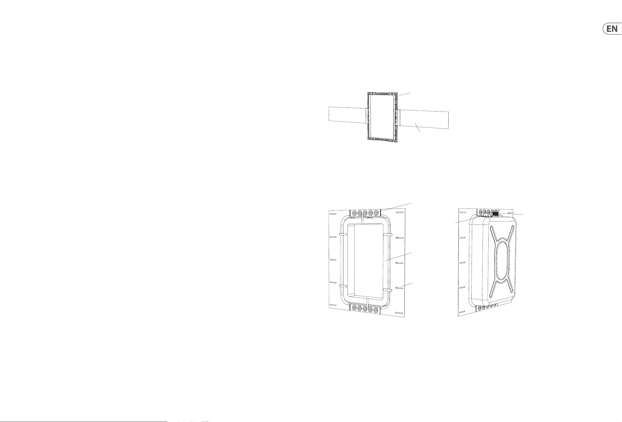
2. Carefully move the Back Can to the chosen location between the wall studs, and
lift it to the desired height, allowing enough room for the speaker wire to enter the
cable gland (Fig. 1).
3. Make sure that the Back Can is plumb and level, then attach the Back Can to the
wall studs using 5 screws or nails per stud.
Fig. 1. Install the Back Can between the studwork
Optional Pre-Mount Kit Installation
Two optional Pre-Mount Kits are available:
• The PMK 5 IW is used with the PCI 5DC IW wall-mount loudspeaker
• The PMK 6 IW is used with the PCI 6DC IW and QCI 6DC wall-mount loudspeakers
These provide a rectangular surround for a strong mounting surface for the clamping
mechanism of the loudspeaker, and they make it easier to install the drywall.
The PMK kits can be used with or without the Back Can.
The procedure below describes the installation of the PMK 6 IW pre-mount kit
into a Back Can that has been installed into the wall studs and wired following the
procedure shown on the previous page. The installation of the PMK 5 IW pre-mount
kit is otherwise identical.
Preparing the PMK Pre-Mount Kit
1. Each pre-mount kit consists of two mounting brackets, a rectangular frame, and
four small clips that help secure the brackets to the frame.
2. Attach the mounting brackets to the top and bottom (shortest sides) of the
rectangular frame (Fig. 3). Press the four clips in place, to hold the brackets in
position
3. The PMK kit can also be used without the Back Can, in which case, the mounting
brackets are connected to the longer sides of the frame (Fig. 4).
1
Wiring the Back Can
WARNING: To avoid potential damage to your loudspeaker, ensure that the amplifier
is switched OFF prior to connecting or disconnecting any cables.
The speaker wire connections are made to the cable entry gland into the Back Can. A
loop is provided to secure the cable before it enters the cable gland.
1. Loop the speaker wire once around the provided cable loop, and pass the cable
through the cable gland and into the Back Can (Fig. 2) and past the acoustic foam
inside the Back Can. Leave enough slack to make the connections when that time
comes. Tighten the cable gland, and tie down the speaker cable to prevent it
moving and rattling in operation. Make sure that the speaker cable does not come
into contact with nails or screws that might damage the electrical insulation.
2
Loop for strain
relief of cable
Cable Entry
3
Fig. 3. Installing the PMK brackets to the frame
Fig. 2. Install the wiring into the Back Can
Fig. 4. PMK assembly, for use without the IW Back Can
Page 5

8 PMK IW and Back Can IW Quick Start Guide 9
Installing the PMK into the Back Can
1. Hold the PMK assembly onto the Back Can, with the rectangular lip of the frame
pointing outwards, into the room (Fig. 5).
2. Make sure the PMK assembly is centered, plumb, and level. Secure it to the
Back Can using the four screws, and using the existing holes at the top and bottom
of the Back Can (Fig. 6).
3. Apply adhesive EVA tape around the front of the Back Can/PMK assembly as shown
(Fig. 6b). We recommend EVA tape width 65 mm, thickness 3 mm, or similar. Note:
Make sure that there are no gaps between the vertical and horizontal lengths of
tape, so it is a continuous rectangle. (Any gaps may aect the performance of the
loudspeaker.) Note: the EVA tape is required, even if the PMK kit is not used.
Front
Lip
Fig. 5. Front of the PMK is the side with the lip
Installing the PMK without the Back Can
If you are not using the Back Can, then there are two ways you can use the PMK kits:
PMK Option 1
1. Cut and add two pieces of 2x4 wood, horizontally as shown in Fig. 7, and nail and
glue them securely in place to the vertical wall studs.
2. Hold the PMK assembly in place, with the rectangular lip of the frame pointing
outwards, into the room.
3. Make sure the PMK assembly is centered, plumb, and level. Secure it to the
horizontal pieces using four screws (Fig. 7).
4. Run speaker wire to this location. Leave enough slack to make the connections
when that time comes. Tie down the speaker cable to prevent it moving and
rattling in operation. Make sure that the speaker cable does not come into contact
with nails or screws that might damage the electrical insulation.
PMK Option 2
1. Assemble the PMK with the mounting brackets attached to the longer sides of
the PMK frame and then attach the PMK to the vertical wall studs. (See Fig. 4 on
pag e 7).
2x4"
2x4"
Fig. 7. PMK Attached to horizontal pieces
2. Hold the PMK assembly onto the wall studs, with the rectangular lip of the frame
pointing outwards, into the room.
3. Make sure the PMK assembly is centered, plumb, and level. Secure it to the wall
studs using four woodscrews.
4. Run speaker wire to this location (Fig. 8). Leave enough slack to make the
connections when that time comes. Tie down the speaker cable to prevent it
moving and rattling in operation. Make sure that the speaker cable does not come
into contact with nails or screws that might damage the electrical insulation.
Fig. 8. PMK attached to Wall Studs
Fig. 6. Install the PMK into the Back Can
Fig. 6b. Install the EVA tape to front of Back Can.
Create a continuous rectangle, with no gaps.
Page 6

10 PMK IW and Back Can IW Quick Start Guide 11
Installing the Drywall
1. The installation of drywall around the PMK location is best done using a single
large sheet with the vertical center line centered over the PMK vertical centerline
(Fig. 9).
2. If you want to cut the drywall aperture before installation, use the PMK aperture
as a guide. Step 5 below describes cutting after the installation. Use whichever
method you prefer.
3. Use adhesive on the wall studs and the front face of the Back Can (if used), and
install the drywall using drywall screws approximately 8 to 10 inches apart. This
will help prevent wall rattling and drywall movement and noises during operation.
If the loudspeaker is being installed on an interior wall, then adhesive and ex tra
screws may also be added to the drywall used in the room behind the loudspeaker.
4. Note: Before adding any drywall screws where the metal Back Can is installed, drill
small pilot holes into the metal of the Back Can.
5. After the drywall installation, carefully cut out the hole in the drywall with a
suitable handtool, using the inside aperture of the PMK as a guide (Fig. 10 and 11).
Be careful not to cut the speaker wires or cut into the Back Can acoustic foam.
Make sure the drywall aperture is no larger than the inside aperture of the PMK
frame. Remove any dust or debris from within the Back Can.
6. The PCI 5DC IW, PCI 6DC IW, and QCI 6DC IW quick start guide includes the
procedures for installing the loudspeakers into the wall apertures.
Fig. 9. Drywall Screws, PMK with Back Can
Cutout Procedure without the PMK
If you are using the Back Can, but not the PMK pre-mount kits,
procedure below for cutting out the drywall.
Rectangular cutout templates are supplied with the loudspe
guide for cutting out the correctly sized hole in the wall
F
ollow the procedure steps below in the order in which they are presented. Read all
the instructions before starting.
1. In the position of the Back Can, add the supplied template to the wall, centered
exactly on the center of the Back Can IW, and in the Portrait Orientation.
2. Using the template, carefully cut out a hole in the drywall using a suitable
handtool. Be careful not to damage the Back Can IW, its acoustic foam, or the
speaker wires. Remove any dust and debris from the hole (Fig. 13 and 14).
3. The PCI 5DC IW, PCI 6DC IW, and QCI 6DC IW quick start guide includes the
procedures for installing the loudspeakers into the wall apertures.
then follow this
akers, and act as a
(Fig. 12).
Fig. 12. Drywall Cutout Dimensions
Fig. 10. Drywall Screws, PMK without Back Can
Fig. 11. Drywall Cutout (with PMK)
Fig. 13. Back Can IW without PMK
Fig. 14. Drywall Cutout
Page 7

12 PMK IW and Back Can IW Quick Start Guide 13
490 [19.3]
500 [19.7]
Dimensions Dimensions
Back Can IW PMK 5 IW
250 [9.8]
429 [16.9]
3.5 [0.14] 93 [3.6]
538 [21.2]
70 [2.8]
140 [5.5]
4.5 [0.18] TYP
3.5 [0.14] TYP
301 [11.8]
Dimensions are mm [inch]
461 [18.1]
874 [34.4]
258 [10.2]
228 [9.0]
189 [7.4]
153 [6.0]
228 [9.0]
258 [10.2]
99 [3.9]
20.0 [0.79]
10.0 [0.39]
943 [37.1]
10.0 [0.39]
20.0 [0.79]
99 [3.9]
153 [6.0]
189 [7.4]
Side Mounted Wings End Mounted Wings
Dimensions are mm [inch]
Page 8

14 PMK IW and Back Can IW Quick Start Guide 15
99 [3.9]
Dimensions
PMK 6 IW
908 [35.8]
311 [12.2]
281 [11.1]
223 [8.8]
187 [7.4]
996 [39.2]
20.0 [0.79]
10.0 [0.39]
281 [11.1]
311 [12.2]
Other important information
Important information
1. Register online. Please register your new
Music Tribe equipment right after you purchase it by
visiting tannoy.com. Registering your purchase using our
simple online form helps us to process your repair claims
more quickly and eciently. Also, read the terms and
conditions of our warranty, if applicable.
2. Malfunction. Should your Music Tribe
Authorized Reseller not be located in your vicinity,
you may contact the Music Tribe Authorized Fulller for
your country listed under “Support” at tannoy.com. Should
your country not be listed, please check if your problem
can be dealt with by our “Online Support” which may also
be found under “Support” at tannoy.com. Alternatively,
please submit an online warranty claim at behringer.com
BEFORE returning the product.
3. Power Connections. Before plugging the
unit into a power socket, please make sure you are using
the correct mains voltage for your particular model.
Faulty fuses must be replaced with fuses of the same type
and rating without exception.
10.0 [0.39]
20.0 [0.79]
99 [3.9]
187 [7.4]
223 [8.8]
Side Mounted Wings End Mounted Wings
Dimensions are mm [inch]
Page 9

 Loading...