

Page 1

Quick Start Guide
AMS SERIES
Surface mount loudspeakers
All AMS 5 Models
All AMS 6 Models
All AMS 8 Models
Page 2
1 Introduction
This Quick Start Guide (QSG) provides the basic
information required to install and connect all
models in the Tannoy AMS range of surface-mount
loudspeakers.
For additional information, including product
technology, photo identication of product features,
dimensional drawings, and complete technical
specications, please refer to the full AMS Series
Operation Manual.
2 Safety Notices
Some regional construction codes require the use
of a secondary method of securing loudspeakers to
provide security of a back-up support. A secondary
support line should be attached from the safety
loop on the rear of the product to a source point on
the wall or building structure.
Electrical Safety Notice: to comply with the
standard UL1480, metal-clad exible conduit (BX)
is required for connection to the terminal block for
proper earth grounding.
SAFETY NOTE: In order to comply with the
relevant re safety regulations (i.e. BS 5839:1998),
it is required that in the event of re, that failure of
the circuit to which the loudspeaker is connected
does not occur before evacuation of the building
is complete. Suitable measures include:
• Use of terminal blocks (for connection to primary)
with a melting point of not less than 650°C, for
example constructed from ceramic materials;
• Use of terminal blocks of a lower melting point
but protected with thermal insulation;
• Use of terminal blocks such that, on melting, an
open-circuit or a short-circuit does not occur.
3 Unpacking
Every Tannoy product is carefully inspected before
shipment. After unpacking, please inspect your
product to ensure no damage has occurred in
transit. In the unlikely event of damage, please
notify your dealer and retain all shipping materials
as your dealer may require return shipment.
4 Installation using the
included Yoke Bracket
1. Fix the yoke bracket to an appropriate structural
surface using a suitable xing method.
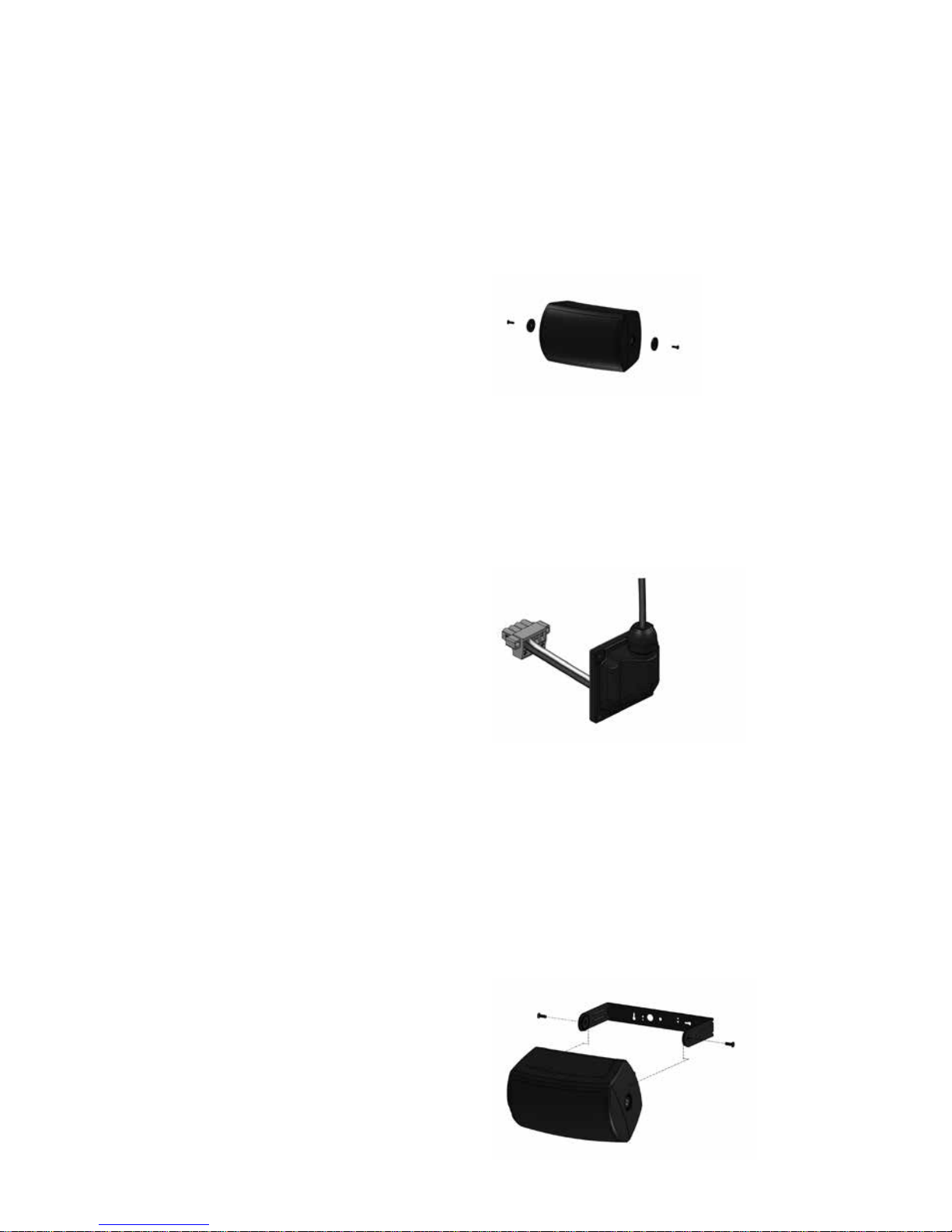
2. Remove the yoke trims from the product to
access the bracket xing points.
3. Remove the rubber grommet from the rear of
the speaker. (Note: The grommet is required only if
installing the product outdoors.
4. Feed the speaker cable through the grommet (if
required). Connect the euro-style plug to the wires,
observing correct polarity.
5. Use pins 1(+) and 2 (-) for connection of
the loudspeaker. Use pins 3 (-) and 4 (+) for
connection of additional loudspeakers in a
distributed line. Note: Tighten pins 3 and 4 even if
not used to prevent vibration of the screws.
6. Place the loudspeaker inside the yoke bracket.
Position buers between bracket and loudspeaker
as shown. Attach with supplied xings using a
5mm Allen key. Use the longer hex screws supplied
when mounting the yoke bracket.
Page 3

7. Connect the euro plug. If required, replace the
rubber grommet and t snugly for a watertight seal.
8. Connect a secondary support line to the safety
tab at the rear of the cabinet.
5 Setting transformer taps
1. The rotary transformer tapping switch is found
on the top of models with 5-inch drivers, and
on the bottom of models with 6-inch and 8-inch
drivers.
CAUTION: The loudspeaker is supplied with the
tap switch set in low impedance mode. Never
connect the loudspeaker to a 70/100V amplier
output while switched to low impedance mode.
2. Set the rotary switch to the appropriate position
for low impedance operation or for use in 70/100V
distributed systems. Models with 5-inch drivers are
tted with 30W transformers; models with 6-inch
and 8-inch drivers are tted with 60W transformers.
For more information on setting transformer taps
in distributed systems, please refer to the full AMS
Series Operation Manual.
6 Installation using the
optional accessory bracket
An optional accessory bracket is available that
allows exible re-orientation of the loudspeaker
on the horizontal and vertical axes. Instructions
for installation and adjustment are included with
the bracket, and also are included in the full AMS
Series Operation Manual. Following installation, set
the transformer taps according to Section 5.
Page 4

Tannoy operates a policy of continuous research and development. The introduction of new materials or
manufacturing methods will always equal or exceed the published specications. All specications are
subject to change without notice. Copyright (c) 2015 Tannoy Limited. All rights reserved.
6481 0678 / 120315
tannoypro.com
 Loading...