

Page 1
1
Page 2
2
Trademark
All trademarks are the property of their respecti ve owners.
Version
User’s Manual V1.1 for Tangent Mini V.
Symbol description
Caution: refers to important information t hat can help you properly use the Mini V,
and how to avoid problems.
Warning: indicates that a potential risk of hardware da mage or phy sical injury may
exist.
WEEE:
The use of this symbol indicates that this product may not be treated as ho usehold
waste. By ensuring this product is disposed of correctly, you will help prevent
potential negative consequences for the env ironment and human health. For more
detailed information about recycling of this product, please contact your local city
office, your household waste di sposal service or Tangent.
Page 3
3
Safety Notice
Before using this product please read the safety notices, below, carefully. This will help to extend
the product’s lifecycle, and ensure n ormal operation.
When Mini V is working, please make sure its ventilation system is working.
The power adapter is dissipating heat during normal use, please be sure not to cov er i t and
keep it away from your body to prevent discomfort or injury by heat exposure.
Please use the power adapter that comes with the product’s package; the wrong power
adapter may damage your device.
Make sure all the peripherals are properly connected before using the Mini V.
This product should only be used in an environment with ambient temperatures between 0ºC
and 40ºC.
Always shut down the computer before install ing or uninstalling any peripheral t hat does not
support hot plug.
Disconnect all peripherals before servici ng or disassembling this device.
Please do not disassemble this product by y ourself , any disassembly not approved by the
original manufacturer may result in malfunction, and void warranty.
Risk of explosion if battery is replaced by an i ncor rect type, please dispose of used batteries
according to the instructions.
Page 4
4
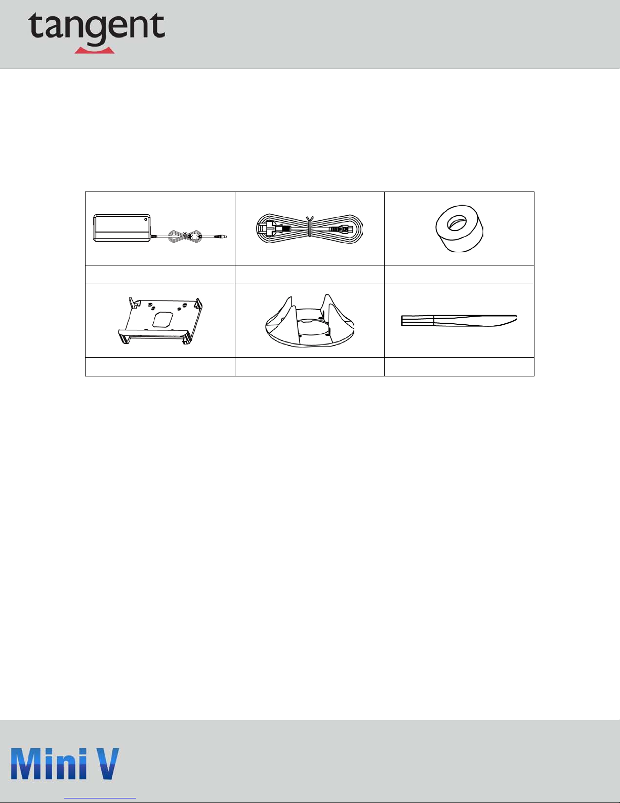
Accessory List
Thank you for choosing the Tangent Mini V. Please check the accessories listed below. If there is
anything broken or lost, please contact Tangent as soon as possible.
Power Adapter Power Cord Magnet Rubber Foot
Vesa Mount Seatbase Opening Tool
Page 5
5
Table of C ontents
CHAPTER 1 ...................................................................................................................... 6
INTRODUCTION OF MINI V .......................................................................................... 6
1.1 TOP VIEW ................................................................................................................... 6
1.2 FRONT SIDE VIEW ...................................................................................................... 7
1.3 BACK SIDE VIEW........................................................................................................ 8
1.4 BOTTOM VIEW ........................................................................................................... 9
CHAPTER 2 .................................................................................................................... 10
PLACEMENT AND CONNECTION OF MINI V .......................................................... 10
2.1 ON THE DESK ........................................................................................................... 10
2.2 ON THE BACK OF A MONITOR .................................................................................... 11
CONNECTION OF MINI V
2.3 CONNECT THE MONITOR .......................................................................................... 13
2.3.1 CONNECT THE USB DEVICES ................................................................................ 13
2.3.2 CONNECT THE NETWORK CABLE .......................................................................... 14
2.3.3 CONNECT THE POWER CORD ................................................................................. 14
Page 6

6
C hapter
1
Introducing Mini V
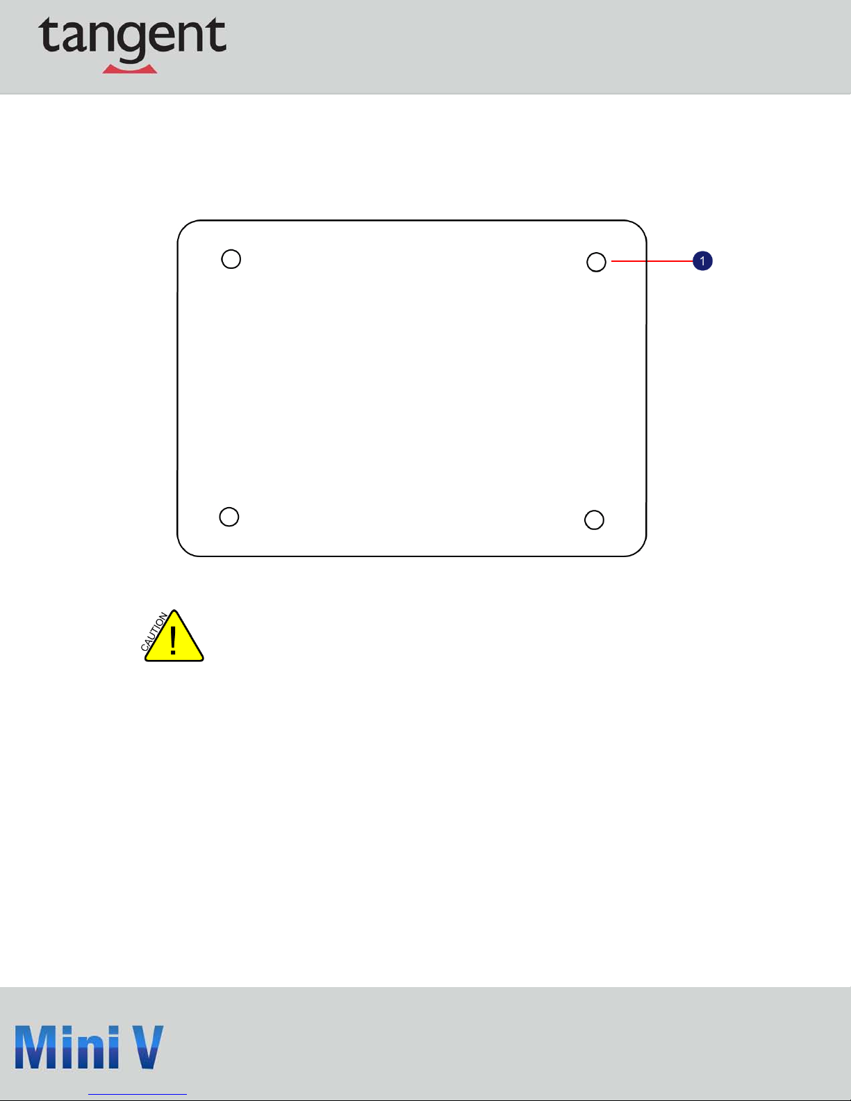
1.1 Top View
No. Name Description
1 Kensington Lock
Attach a Kensington security sy st em or a
compatible lock to secure your Mini V.
Page 7

7
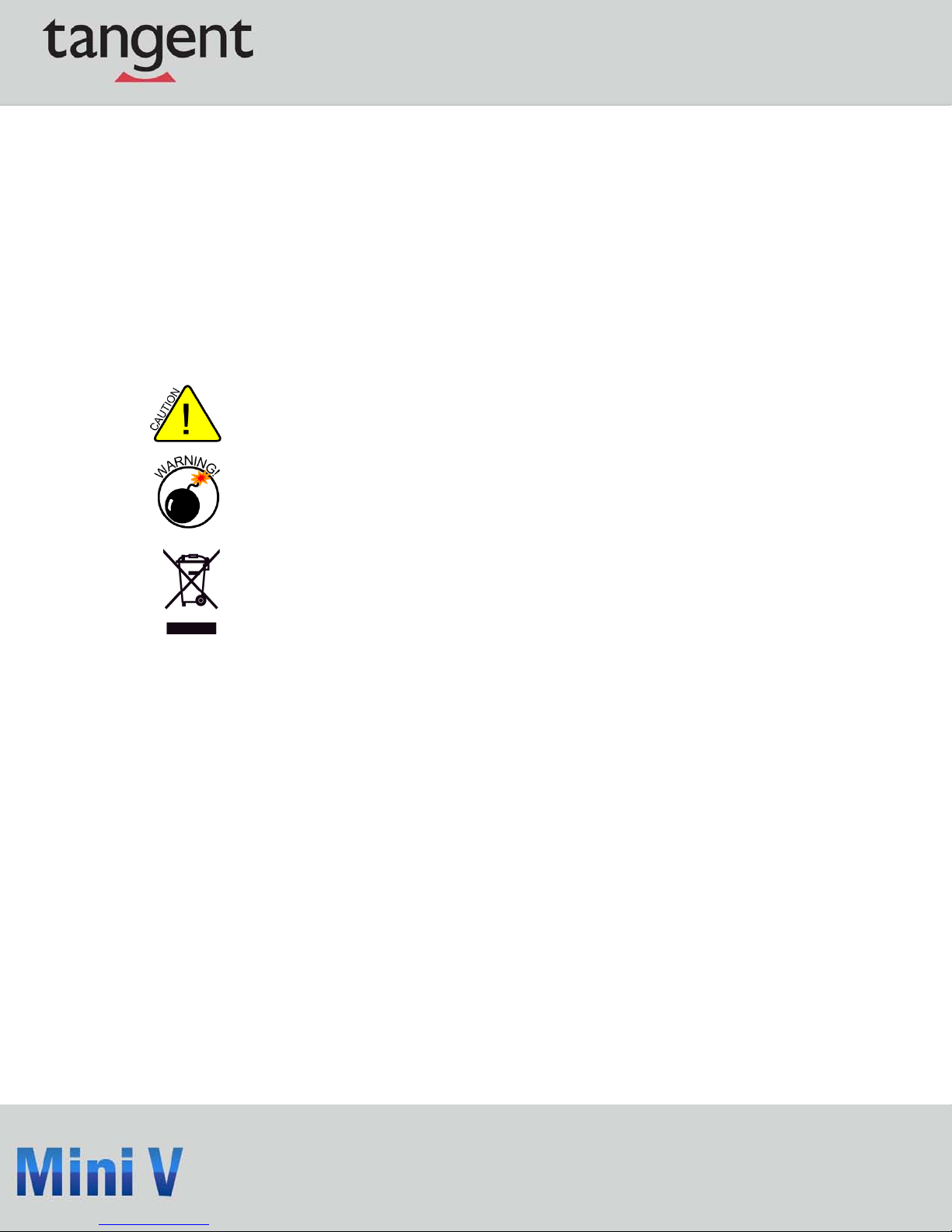
1.2 Front Side View
No. Name Description
1 Headphone Port Connects to a headphone
2 Microphone In and S/PDIF In Port
Connects to a microphone or playba ck
devices with optical connectors(3.5mm jack)
3 Multi-Function Card Reader
Support SD/SDHC/SDXC/MS/MS Pro/MMC
memory cards
4 USB 3.0 Ports
Connect to USB devices
Caution:Before using it, you need to install
the “ASMedia USB3.0 driver” in the Driver
CD.
5 Suspend Butt on Enter suspend mode in operating system
6
Power Button with Integrated LED
Indicator
Turning the power on/off, Indicates system
states
Page 8

8
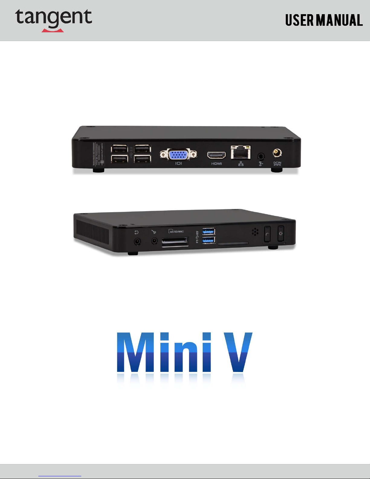
1. 3 B ack S ide View
No. Name Description
1 USB 2.0 Ports Connects to USB devices
2 Display Output Port (VGA) Connects to display devi ce
3 HDMI Port Connects to HDMI audio and video
4 Network Port St andard RJ-45 network port
5 Line Out and S/PDIF Out Port
Connects to powered analog speakers or
recording devices with optical
connectors(3.5mm jack)
6 Power Input Port Connects to the power adapter
Page 9
9
1. 4 B ottom V iew
There are four Magnet-Metal-Feet in the package. Just align them to the sheet
metal on the bottom. The feet can seat and protect the Mini V when it is placed on
a tabletop.
Page 10

10
C hapter
2
Placement of the Mini V
2.1 On a Desk
2.1.1. You can install your Mini V in the Seatbase, as shown below:
Page 11

11
2.1.2. If there is enough space on your desk, you can simply put your Mini V on
the tabletop as shown below.
2.2 On the Back of a Monitor
This is the best space-saving way.
2.2.1. Use four screws to fasten the VESA Mount onto the display back.
To install this VESA Mount, your display must follow VESA75/VESA100 standard. The
holes on your display have different spaces between them, and safely fasten the VESA
Mount onto your display. The VESA mounting plat e is designed to attach to either
75x75 or 100x100 VESA compliant monitors.
Page 12

12
2.2.2. Fit the Mini V into the VESA Mount with power button located at the top for
easy access.
Slide up the Mini V to take it out.
Page 13

13
2.3 Connecting the Mini V
2.3.1. Connect the Monitor
Connect a monitor to the Mini V through the VGA connector.
2.3.2. Connect the USB Devices
Connect USB devices to the USB ports of the Mini V, for example, mouse and key board.
Page 14

14
2.3.3. Connect the Network Cable
Connect LAN cable to the RJ-45 port, with t he other end connected to a hub or switch.
2.3.4. Connecting the Power Cord
Connect the power adapter to the power input port of the Mini V, and push the power button to
start it.
The power adapter dissipates heat during normal use; please make sure not to cover it
and keep it away from your body to prevent dis comfort or injury from heat exposure.
 Loading...