

Page 1

Medix 1700SF
Medical Grade Panel PC
USER’S MANUAL
Copyright ©2008. All rights reserved
All brand names are registered trademarks of their respective owners.
Page 2

Setup
Thank you for purchasing the Medix 1700SF. Designed with
durability and reliability in mind, the Medix 1700SF meets the
demands in medical environments. Please follow all instructions
to ensure maximum unit performance.
Unpacking
After opening the carton, there will be a Monitor display unit with
an accessory box. Examine the contents to see if there are
damages to the unit and if all accessories are present.
Setting Up
Please read this manual carefully and keep it for future reference.
Safety Instructions & Cleaning
The unit has undergone various tests in order to comply with
safety standards. Inappropriate use of the open frame unit may
be dangerous. Please follow all instructions to ensure your safety
during the installation and operating process.
Transporting & Placement of Unit
1. When moving the unit on a cart; be very cautious. Quick stops,
excessive forces and uneven surfaces may cause the cart to
overturn and risking the unit to fall.
2. If the Monitor display unit does fall on the ground, immediately
turn the power off and disconnect cords. Then contact a service
technician for repairs. Continual use of the unit may cause a fire
or electric shock. Also, do not attempt to repair the unit yourself.
2. Having two or more people transporting the display unit is
recommended. In addition, when installing the unit by
suspending it also requires two or more people.
3. Before suspending the unit, make sure the material used for
suspension is sturdy and stable. If not properly suspended, the
display unit may fall and cause serious injury to people standing
nearby as well as to the unit itself.
4. The display unit may be mounted – only use the mounting
hardware recommended by Tangent.
2
Medix 1700SF User’s Manual
Page 3

Electrical and Power Source
1. The Monitor display unit must operate on a power source as
shown on the specification label. If you are not sure what type of
power supply is used in the area, consult your dealer or local
power supplier.
2. The power cords must not be damaged. Applied pressure,
added heat, and tugging may damage the power cord.
3. The power cord must be routed properly during setup. This
precaution is needed to prevent people from stepping on the
cords or while the unit is suspended to prevent flying objects from
getting tangled with the unit.
4. Do not overload the AC outlets or extension cords. Electrical
shocks or fires may occur from overloading.
5. Do not touch the power source during a thunderstorm.
6. If your hands are wet, do not touch the plug.
7. Use your thumb and index finger, grip firmly on the power cord
to disconnect from the electrical socket. Pulling the power cord
may cause damage.
8. If the unit is not going to be in use for an extended period of
time, remember to disconnect the unit.
9. The Monitor display unit uses voltage between 90-264VAC.
Connect the unit to a power source with the same numerical
value. Please use only the power cord provided to ensure safety
and EMC compliance.
External Environment
1. Do not insert objects into the openings.
2. Do not allow liquids to seep into the internal areas of the
Monitor display unit.
3. Allowing liquids to seep in or inserting objects into the unit may
result in electric shocks and/or short circuit of the internal parts.
Medix 1700SF User’s manual
3
Page 4

4. Do not place the Monitor display unit in high moisture areas.
5. Do not install the Monitor display unit in a wet environment.
6. Do not place near unit near heat generating sources.
7. Do not place the unit in a location where it will come in contact
with fumes or steam.
8. Remember to keep the Monitor display unit away from the
presence of dust.
9. If water has flowed in or seeped in, immediately disconnect the
open frame unit. Then contact a service technician for repairs.
Ventilation Spacing
1. Do not cover or block the openings on the top and back sides of
the display unit. Inadequate ventilation may cause overheating
thus reducing the lifespan of the unit.
2. Unless proper ventilation is present, do not place unit in an
enclosed area; such as a built-in shelf. Keep a minimum distance
of 10 cm between the display unit and wall.
Cleaning the Unit
(1) Remember to turn off the power source and to unplug the
cord from the outlet before cleaning the unit.
(2) Carefully dismount the unit or bring the unit down from
suspension to clean.
(3) Moisten a soft cloth with diluted neutral detergent to clean the
unit.
(4) Take a dry cloth and wipe the unit dry. Remember to avoid
having liquids seep into the internal components and areas of the
Monitor display unit.
Servicing, Repairing, Maintenance & Safety Checks
4
Medix 1700SF User’s Manual
Page 5

1. If the unit is not functioning properly, observe the performance
level of the display closely to determine what type of service may
be needed.
2. Do not attempt to repair the Monitor display unit on your own.
Disassembling the cover exposes users to high voltages and
other dangerous conditions. Notify and request a qualified service
technician for servicing the unit.
3. If any of the following situations occur, turn the power source
off and unplug the unit. Then contact a qualified service
technician
(a) A liquid was spilled on the unit or objects have fallen into the
unit.
(b) The unit is soaked with liquids.
(c) The unit is dropped or damaged.
(d) Smoke or strange odor is flowing out of the operating unit.
(e) The power cord or plug is damaged.
(f) The unit has become dysfunctional.
4. When replacement parts are needed for the Monitor display
unit, make sure service technicians use replacement parts
specified by Tangent, or those with the same characteristics and
performance as the original parts. If unauthorized parts are used
it may result in starting a fire, electrical shock and/or other
dangers.
Medix 1700SF User’s manual
5
Page 6

Table of Contents
Introduction..........................................................7
Product Description .......................................... 7
Package list..................................................... 8
Features ..........................................................9
Specifications .................................................10
Dimension......................................................12
System View ..................................................13
BIOS Setup..........................................................16
Appendix.............................................................36
6
Medix 1700SF User’s Manual
Page 7

Introduction
Product Description
The Medix 1700SF Medical Panel PC is based on Intel Core 2 Duo
processor which delivers a performance improvement of more than 100
percent compared to systems running traditional single-core processors.
With two cores, or computing engines, Medix 1700SF can simultaneously
execute two computing tasks. It accommodates one 2.5” SATA hard disk
drive and up to 2GB DDR SODIM.
The high brightness LCD, low noise solution, integrated multimedia
functions and extensive expansion options make them the perfect
platform upon which to build computing applications.
The Medix 1700SF combines all the features of a powerful computer into
a slim and attractive chassis. The Medix 1700SF has a 17” 400 nits TFT
display with 1280 x 1024 resolution.
The Medix 1700SF is a compact, Giga LAN and selectable WLAN network
compatible PC with full safety and medical approval. Combining the
Medix 1700SF into your computing environment can result in cost
savings and efficient improvements.
Common applications include Surgical, Radiology, PACS (Picture
Archiving Communication Systems), LIS (Lab Information Systems) and
Electronic Medical Record. The Medix 1700SF is designed for the medical
environment.
Medix 1700SF User’s manual
7
Page 8

Package list
Before you begin installing your Medical Station, please make sure that
the following items have been shipped:
• The Medix 1700SF Medical Panel PC
• One CD containing user manual, Tangent drivers
• Power Cable x 1
• Power Adapter x 1
• Touch pen x 1
• Screw x 4 (VESA 75/100 use)
8
Medix 1700SF User’s Manual
Page 9

Features
Intel Core 2 Duo Mobile CPU Solution
17” 400 nits high brightness
High performance and low power system solution
Integrated Compact Flash card reader
Integrated PCMCIA type I/II slot support
Integrated TV tuner with capture card (optional)
Integrated 1.3M pixel Web-CAM (optional)
802.11 b/g wireless LAN Module (optional)
VESA 75/100 compliance Desktop Stand (optional)
VESA 75/100 compliance Wall Mount (optional)
Resistive touch screen (optional)
Plastic construction with medical outlook color
Medix 1700SF User’s manual
9
Page 10

Specifications
[
Hardware Specifications
Display
CPU Support
Disk Drive Space
Expansion
Button
I/O
17” 420 nits SXGA color TFT LCD
Medix 1700SF: Intel® Core 2 Duo T7500 2.2GHz
Medix 1700SF (fanless): Intel
2.5” Hard Disk Drive (SATA-150)
Compact Flash Card reader
One Mini PCI slot; One PCI expansion,
One CF card slot expansion (optional)
One PCMCIA type I/II slot expansion (optional)
Brightness: “+” / ”-“; Sound: “+” / ”-“; Power SW
3 RS-232 ports (1 RS-232/422/485 port)
8 USB 2.0 ports
1 DC-in w/ lock function
1 PS/2 keyboard and 1 PS/2 mouse
2 Gigabit LAN RJ-45 Connectors
Sound:
1 x Line-in
1 x line-out
1 x Mic-in
2 x 2W Speakers on back side
1 x PCI slot
LCD Specifications
Model Name
Display Type
Max. Resolution
Contrast Ratio
Pixel Pitch (mm)
Luminance (cd/m2)
Viewing Angle
Operating Temperature
Brightness Control
10
Medix 1700SF User’s Manual
®
Core 2 Duo Ultra Low
Voltage U75001.06GHz Processor
4 x internal for Web-CAM, touch screen (optional)
4 x on rear bracket
Medix 1700SF
17” color TFT LCD
1280 x 1024
500 : 1 (Typ)
0.264 (per one triad) x 0.264
420 (TYP)
140°(H)
130°(V)
0°C~ 40°C (32°F~104°F)
Yes
Page 11

Note:
All Tangent LCD products are manufactured with High precision
technology. However, ther e are a small numb er of d efective pixels in all
LCD panels that are not able to change color. This is a normal occurrence
for all LCD displays from all man ufacture rs and s hould not b e notice able
or objectionable under normal operation. LCD panels are qualified for
industry standard under the following conditions: total 7 dead pixels on
a screen or if there are 3 within 1 inch square area of each other on the
display.
Mechanical Specifications
Architecture
Front Bezel
Color
Mounting / Holder
Construction
Dimension (WxHxD)
Net Weight
Close-frame
Plastic bezel with resistive touch screen
Medical-white
VESA 75/100mm
3mm ABS + PC TYPE Plastic housing
16.5” x 14.2” x 3.2” (420mmx 360mm x 83 mm)
15.62 lb (7.0 kg)
Packing Filler
PE
Environmental Specifications
Operating Temperature
Storage Temperature
Storage Humidity
Vibration
Shock
Drop
EMI / Safety
IP
Noise
Input Power Rating
Power Consumption
0°C to 40°C (32°F ~104°F)
-20°C to 60°C (-4°F ~140°F)
5% to 95%@ 40°C, non-condensing
0.5G / 5 ~ 500Hz (Random) / operation
Operating: 15g/0.53 oz, 11 ms, half sine wave
Non-operating: 50g/1.76 oz, 11 ms, half sine wave
3 feet (1 Corner, 3 Edge, 6 Surface)
CE / FCC Class B/UL 60601-1/EN 60601-1
Front bezel, IP-65 Certified
Medix 1700SF: Under 35 db (full operation)
Medix 1700SF (fanless): less than 20 db
AC90~264 V, 47 ~ 63 Hz
Medix 1700SF:79.50W
Medix 1700SF (fanless):46.50W
Medix 1700SF User’s manual
11
Page 12

Dimensions
12
Medix 1700SF User’s Manual
Page 13
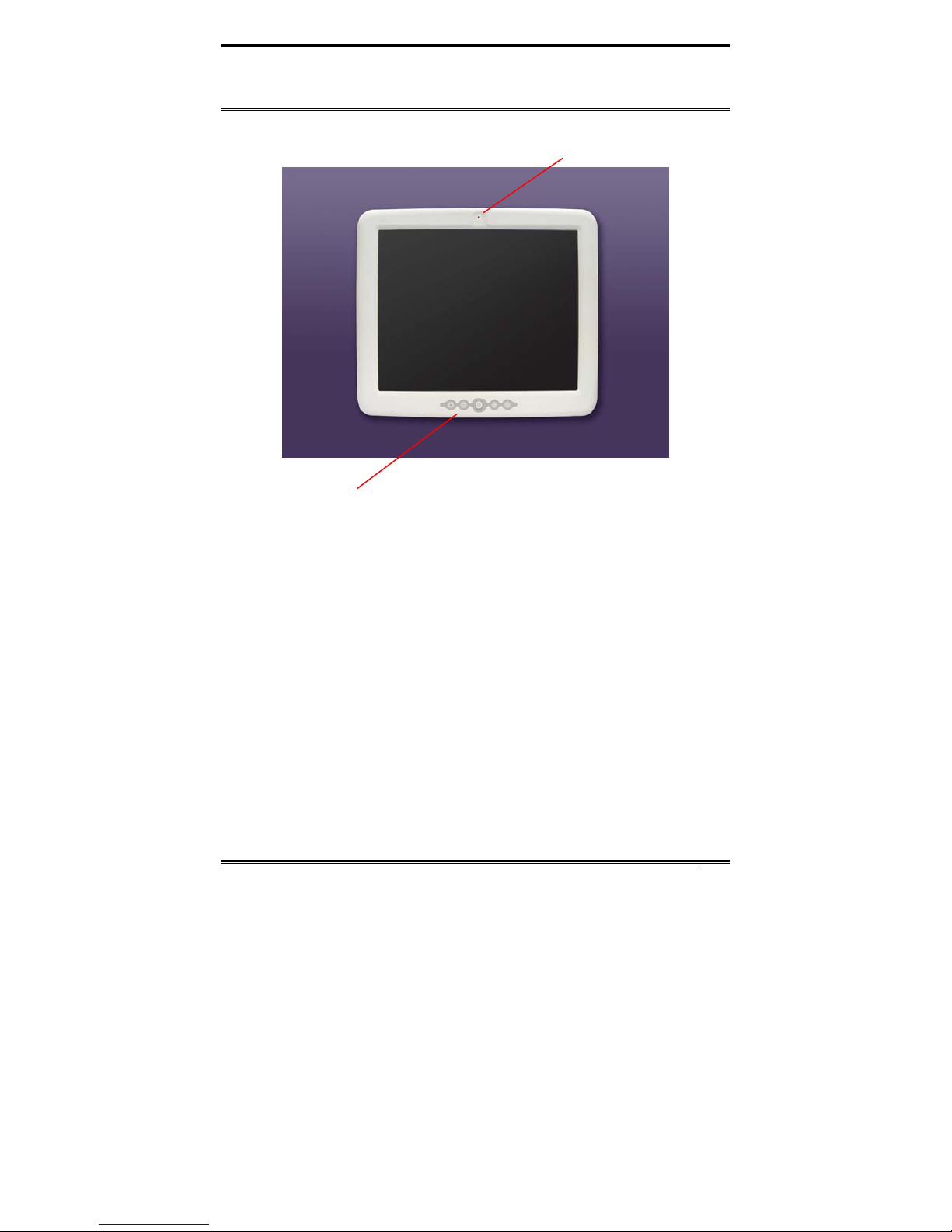
System View
Front View
Webcam (Optional)
Control button at front panel
From left to right
1. Brightness down
2. Brightness up
3. Power
4. Volume down
5. Volume up
Medix 1700SF User’s manual
13
Page 14
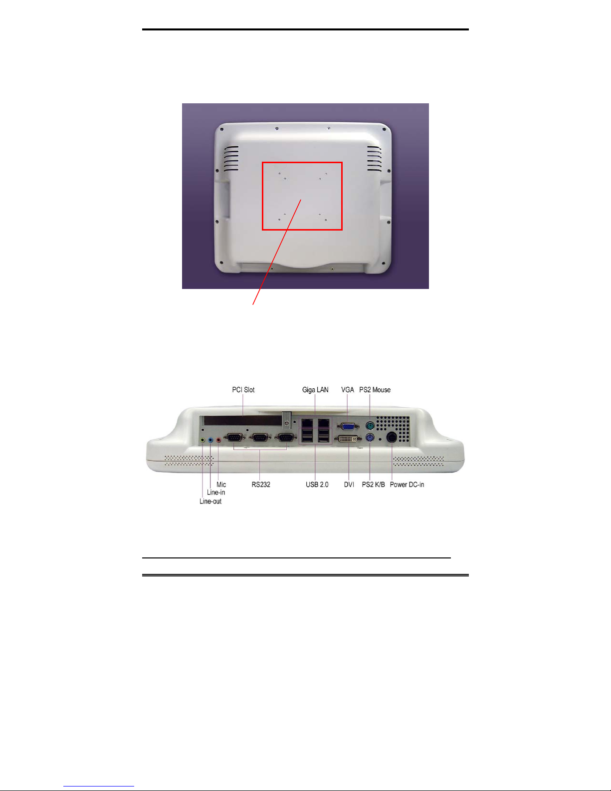
Rear View
VESA 75/100
I/O parts
14
Medix 1700SF User’s Manual
Page 15

Side view
Medix 1700SF User’s manual
15
Page 16

BIOS Setup
BIOS Introduction
The Award BIOS (Basic Input/Output System) installed in your
computer system’s ROM supports Intel processors. The BIOS
provides critical low-level support for a standard device such as
disk drives, serial ports and parallel ports. It also adds virus and
password protection as well as special support for detailed
fine-tuning of the chipset controlling the entire system.
Medix 1700SF BIOS Set up
The Award BIOS provides a Setup utility program for specifying
the system configurations and settings. The BIOS ROM of the
system stores the Setup utility. When you turn on the computer,
the Award BIOS is immediately activated. Pressing the <Del> key
immediately allows you to enter the Setup utility. If you are a
little bit late pressing the <Del> key, POST (Power On Self Test)
will continue with its test routines, thus preventing you from
invoking the Setup. If you still wish to ent er Setup, restart the
system by pressing the ”Reset” button or simultaneously
pressing the <Ctrl>, <Alt> and <Delete> keys. You can also
restart by turning the system Off and back On again. The
following message will appear on the screen:
Press <DEL> to Enter Setup
In general, you press the arrow keys to highlight items, <Enter>
to select, the <PgUp> and <PgDn> keys to change entries, <F1>
for help and <Esc> to quit.
When you enter the Setup utility, the Main Menu screen will
appear on the screen. The Main Menu allows you to select from
various setup functions and exit choices.
16
Medix 1700SF User’s Manual
Page 17

Phoenix - Award BIOS CMOS Setup Utility
Standard CMOS Features Frequency/Voltage Control
Advanced BIOS Features Load Fail-Safe Defaults
Advanced Chipset Features Load Optimized Defaults
Integrated Peripherals Set Supervisor Password
Power Management Setup Set User Password
PnP/PCI Configurations Save & Exit Setup
PC Health Status Exit Without Saving
ESC : Quit : Select Item
F10 : Save & Exit Setup
Time, Date, Hard Disk Type…
The section below the setup items of the Main Menu displays the
control keys for this menu. At the bottom of the Main Menu just
below the control keys section, there is another section, which
displays information on the currently highlighted item in the list.
Note: If the system cannot boot after making and
saving system changes with Setup, the Award
BIOS supports an override to the CMOS
settings that resets your system to its default.
Warning: It is strongly recommended that you avoid
making any changes to the chipset defaults.
These defaults have been carefully chosen by
both Award and your system manufacturer to
provide the absolute maximum performance
and reliability. Changing the defaults could
cause the system to become unstable and
crash in some cases.
Medix 1700SF User’s manual
17
Page 18

Standard CMOS Setup
“Standard CMOS Setup” choice allows you to record some basic
hardware configurations in your computer system and set the
system clock and error handling. If the motherboard is already
installed in a working system, you will not need to select this
option. You will need to run the Standard CMOS option, however,
if you change your system hardware configurations, the onboard
battery fails, or the configuration stored in the CMOS memory is
lost or damaged.
Date (mm:dd:yy) Wed, Apr 28, 2004 Item Help
Time (hh:mm:ss) 00 : 00 : 00 Menu Level >
IDE Channel 0 Master None
IDE Channel 0 Slave None
IDE Channel 1 Master None
IDE Channel 1 Slave None
Drive A 1.44M, 3.5 in.
Drive B None
Video EGA/VGA
Halt On All Errors
Base Memory 640K
Extended Memory 129024K
Total Memory 130048K
At the bottom of the menu are the control keys for use on this
menu. If you need any help in each item field, you can press the
<F1> key. It will display the relevant information to help you. The
memory display at the lower right-hand side of the menu is
read-only. It will adjust automatically according to the memory
changed. The following describes each item of this menu.
Date
The date format is:
Day : Sun to Sat
Month : 1 to 12
Date : 1 to 31
Year : 1999 to 2099
Phoenix - Award BIOS CMOS Setup Utility
Standard CMOS Features
Change the day, month,
Year and century
18
Medix 1700SF User’s Manual
Page 19

To set the date, highlight the “Date” field and use the PageUp/
PageDown or +/- keys to set the current time.
Time
The time format is:
Minute : 00 to 59
Second : 00 to 59
Hour : 00 to 23
To set the time, highlight the “Time” field and use the <PgUp>/
<PgDn> or +/- keys to set the current time.
IDE Channel Master/Slave
The onboard PCI IDE connector provides Primary and Secondary
channels for connecting up to two IDE hard disks or other IDE
devices.
Press <Enter> to configure the hard disk. The selections include
Auto, Manual, and None. Select ‘Manual’ to define the drive
information manually. You will be asked to enter th e following
items.
CYLS : Number of cylinders
HEAD : Number of read/write heads
PRECOMP : Write precompensation
LANDING ZONE : Landing zone
SECTOR : Number of sectors
The Access Mode selections are as follows:
CHS (HD < 528MB)
LBA (HD > 528MB and supports
Logical Block Addressing)
Large (for MS-DOS only)
Auto
Remarks: The main board supports two serial ATA ports and are
represented in this setting as IDE Channel 0.
Drive A / Drive B
These fields identify the types of floppy disk drive A or drive B that
has been installed in the computer. The available specificat ions
are:
360KB
5.25 in.
1.2MB
5.25 in.
720KB
3.5 in.
1.44MB
3.5 in.
2.88MB
3.5 in.
Medix 1700SF User’s manual
19
Page 20

Video
This field selects the type of video display card installed in your
system. You can choose the following video display cards:
EGA/VGA For EGA, VGA, SEGA, SVGA
or PGA monitor adapters. (default)
CGA 40 Power up in 40 column mode.
CGA 80 Power up in 80 column mode.
MONO For Hercules or MDA adapters.
Halt On
This field determines whether or not the system will halt if an
error is detected during power up.
No errors The system boot will not be halted for
any error that may be detected.
All errors Whenever the BIOS detects a
non-fatal error, the system will stop
and you will be prompted.
All, But Keyboard The system boot will not be halted for
a keyboard error; it will stop for all
other errors
All, But Diskette The system boot will not be halted for
a disk error; it will stop for all other
errors.
All, But Disk/Key The system boot will not be halted for
a key- board or disk error; it will stop
for all others.
20
Medix 1700SF User’s Manual
Page 21

Advanced BIOS Features
This section allows you to configure and improve your system and
allows you to set up some system features according to your
preference.
CPU Feature Press Enter ITEM HELP
Hard Disk Boot Priority Press Enter
Virus Warning Disabled
CPU L1 and L2 Cache Enabled
Quick Power On Self Test Enabled
First Boot Device Floppy
Second Boot Device Hard Disk
Third Boot Device CDROM
Boot Other Device Enabled
Swap Floppy Drive Disabled
Boot Up Floppy Seek Disabled
Boot Up NumLock Status On
Gate A20 Option Fast
Typematic Rate Setting Disabled
Typematic Rate (Chars/Sec) 6
Typematic Delay (Msec) 250
Security Option Setup
APIC Mode Enabled
MPS Version Control for OS 1.4
OS Select For DRAM>64MB Non-OS2
Report No FDD For WIN 95 Yes
Small Logo (EPA) Show Enabled
CPU Feature
Press Enter to configure the settings relevant to CPU Feature.
Hard Disk Boot Priority
With the field, there is the option to choose, aside from the hard disks
connected, “Bootable add-in Cards” which refers to other external
devices.
Virus Warning
If this option is enabled , an alarm message will be displayed when trying
to write on the boot sector or on the partition table on the disk, which is
typical of the virus.
CPU L1 and L2 Cache
Cache memory is additional memory that is much faster than
conventional DRAM (system memory). CPUs from 486-type on up
contain internal cache memory, and most, but not all, modern
PCs have additional (external) cache memory. When the CPU
requests data, the system transfers the requested data from the
Phoenix - Award BIOS CMOS Setup Utility
Advanced BIOS Features
Menu Level >
Medix 1700SF User’s manual
21
Page 22

main DRAM into cache memory, for even faster access by the
CPU. These items allow you to enable (speed up memory access)
or disable the cache function. By default, these items are
Enabled.
Quick Power On Self Test
When enabled, this field speeds up the Power On Self Test (POST)
after the system is turned on. If it is set to Enabled, BIOS will skip
some items.
First/Second/Third Boot Device
These fields determine the drive that the system searches first for
an operating system. The options available include Floppy,
LS120, Hard Disk, CDROM, ZIP100, USB-Floppy, USB-ZIP,
USB-CDROM, LAN and Disable.
Boot Other Device
These fields allow the system to search for an OS from other
devices other than the ones selected in the First/Second/Third
Boot Device.
Swap Floppy Drive
This item allows you to determine whether or not to enable Swap
Floppy Drive. When enabled, the BIOS swaps floppy drive
assignments so that Drive A becomes Drive B, and Drive B
becomes Drive A. By default, this field is set to Disabled.
Boot Up Floppy Seek
This feature controls whether the BIOS checks for a floppy drive
while booting up. If it cannot detect one (eith er due to improper
configuration or its absence), it will flash an error message.
Boot Up NumLock Status
This allows you to activate the NumLock function after you power
up the system.
Gate A20 Option
This field allows you to select how Gate A20 is worked. Gate A20
is a device used to address memory above 1 MB.
Typematic Rate Setting
When disabled, continually holding down a key on your keyboard
will generate only one instance. When enabled, you can set the
22
Medix 1700SF User’s Manual
Page 23

two typematic controls listed next. By default, this field is set to
Disabled.
Typematic Rate (Chars/Sec)
When the typematic rate is enabled, the system registers
repeated keystrokes speeds. Settings are from 6 to 30 characters
per second.
Typematic Delay (Msec)
When the typematic rate is enabled, this item allows you to set
the time interval for displaying the first and second characters. By
default, this item is set to 250msec.
Security Option
This field allows you to limit access to the System and Setup. The
default value is Setup. When you select System, the system
prompts for the User Password every time you boot up. When you
select Setup, the system always boots up and prompts for the
Supervisor Password only when the Setup utility is called up.
APIC Mode
APIC stands for Advanced Programmable Interrupt Controller.
The default setting is Enabled.
MPS Version Control for OS
This option specifies the MPS (Multiprocessor Specification)
version for your operating system. MPS version 1.4 added
extended configuration tables to improve support for multiple PCI
bus configurations and improve future expandability. The default
setting is 1.4.
OS Select for DRAM > 64MB
This option allows the system to access greater than 64MB of
DRAM memory when used with OS/2 that depends on certain
BIOS calls to access memory. The default setting is Non-OS/2.
Report No FDD For WIN 95
If you are using Windows 95/98 without a floppy disk drive, select
Enabled to release IRQ6. This is required to pass Windows
95/98's SCT test. You should also disable the Onboard FDC
Controller in the Integrated Peripherals screen when there's no
Medix 1700SF User’s manual
23
Page 24

floppy drive in the system. If you set this feature to Disabled, the
BIOS will not report the missing floppy drive to Win95/98.
Small Logo (EPA) Show
The EPA logo appears at the right side of the monitor screen when
the system is boot up. The default setting is Enabled.
Advanced Chipset Features
This Setup menu controls the configuration of the chipset.
DRAM Timing Selectable By SPD ITEM HELP
CAS Latency Time 4
DRAM RAS# to CAS# Delay 4
DRAM RAS# Precharge 4
Precharge delay (tRAS) 12
System Memory Frequency 533MHZ
SLP_S4# Assertion Width 1 to 2 Sec
System BIOS Cacheable Enabled
Video BIOS Cacheable Disabled
Memory Hole at 15M-16M Disabled
PCI Express Root Port Func Press Enter
** On-Chip VGA Setting **
PEG/On Chip VGA Control Auto
On-Chip Frame Buffer Size 8MB
DVMT Mode DVMT
DVMT/FIXED memory Size 128MB
Boot Display Auto
Panel Scaling Auto
Panel Number 1024x768 18 bit SC
Onboard PCI-E LAN Enable
LAN PXE Option ROM Disabled
DRAM Timing Selectable
This option refers to the method by which the DRAM timing is
selected. The default is By SPD.
CAS Latency Time
You can configure CAS latency time in HCLKs as 2 or 2.5 or 3. The
system board designer should set the values in this field,
depending on the DRAM installed. Do not change the values in
this field unless you change specifications of the installed DRAM
or the installed CPU.
DRAM RAS# to CAS# Delay
Phoenix - Award BIOS CMOS Setup Utility
Advanced Chipset Features
Menu Level >
24
Medix 1700SF User’s Manual
Page 25

This option allows you to insert a delay between the RAS (Row
Address Strobe) and CAS (Column Address Strobe) signals. This
delay occurs when the SDRAM is written to, read from or
refreshed. Reducing the delay improves the performance of the
SDRAM.
DRAM RAS# Precharge
This option sets the number of cycles required for the RAS to
accumulate its charge before the SDRAM refreshes. The default
setting for the Active to Precharge Delay is 4.
Precharge Delay (tRAS)
The default setting for the Precharge Delay is 12.
System Memory Frequency
The default setting is 533MHz.
SLP_S4# Assertion Width
The default setting is 1 to 2 Sec.
System BIOS Cacheable
The setting of Enabled allows caching of the system BIOS ROM at
F000h-FFFFFh, resulting in better system performance.
However, if any program writes to this memory area, a system
error may result.
Video BIOS Cacheable
The Setting Enabled allows caching of the video BIOS ROM at
C0000h-F7FFFh, resulting in better video performance.
However, if any program writes to this memory area, a system
error may result.
Memory Hole at 15M-16M
In order to improve performance, certain space in memory can be
reserved for ISA cards. This memory must be mapped into the
memory space below 16 MB. The choices are Enabled and
Disabled.
On-Chip VGA Setting
The fields under the On-Chip VGA Setting and their default
settings are:
PEG/On Chip VGA Control: Auto
On-Chip Frame Buffer Size: 8MB
Medix 1700SF User’s manual
25
Page 26

DVMT Mode: DVTM
DVMT/Fixed Memory Size: 128MB
Boot Display: Auto
Panel Scaling: Auto
Panel Number: 1024x768 18 bit SC
Panel Scaling
The default setting is Auto. The options available include On and
Off.
Panel Number
These fields allow you to select the LCD Panel type. The default
values for these ports are:
640x480 18bit SC
800x480 18bit SC
800x600 18bit SC
1024x768 18bit SC
1280x1024 18bit DC
1280x768 18bit SC
1400x1050 18bit DC
1600x1200 18bit DC
Onboard PCI-E LAN
By default, this setting is disabled.
LAN PXE Option ROM
By default, this setting is disabled.
26
Medix 1700SF User’s Manual
Page 27

Integrated Peripherals
This section sets configurations for your hard disk and other
integrated peripherals. The first screen shows three main items
for user to select. Once an item selected, a submenu appears.
Details follow.
Phoenix - Award BIOS CMOS Setup Utility
Integrated Peripherals
OnChip IDE Device
Onboard Device
SuperIO Device
Press Enter ITEM HELP
Press Enter Menu Level >
Press Enter
Phoenix - AwardBIOS CMOS Setup Utility
IDE HDD Block Mode
On-chip Primary PCI IDE
IDE Primary Master PIO
IDE Primary Slave PIO
IDE Primary Master UDMA
IDE Primary Slave UDMA
On-Chip Secondary PCI IDE
IDE Secondary Master PIO
IDE Secondary Slave PIO
IDE Secondary Master UDMA
IDE Secondary Slave UDMA
*** On-Chip Serial ATA Setting
***
On-Chip Serial ATA Auto
PATA IDE Mode Secondary
SATA port P0, P2 is Primary
Phoenix - AwardBIOS CMOS Setup Utility
USB Controller
USB 2.0 Controller
USB Keyboard Support
AC97 Audio Select Auto
Phoenix - AwardBIOS CMOS Setup Utility
POWER ON Function BUTTON ONLY
KB Power ON Password Enter
Hot Key power ON Ctrl-F1
Onboard FDC Controller Disabled
Onboard Serial Port 1 3F8/IRQ4
Onboard Serial Port 2 2F8/IRQ3
UART Mode Select Normal
Medix 1700SF User’s manual
OnChip IDE Device
Enabled ITEM HELP
Enabled
Auto
Menu Level >
Auto
Auto
Auto
Enabled
Auto
Auto
Auto
Auto
Onboard Device
Enabled ITEM HELP
Enabled
Menu Level >
Disabled
SuperIO Device
ITEM HELP
Menu Level >
27
Page 28

RxD , TxD Active Hi, Lo
IR Transmission Delay Disabled
UR2 Duplex Mode Half
Use IR Pins IR-Rx2Tx2
PWRON After PWR-Fail Off
IDE HDD Block Mode
This field allows your hard disk controller to use the fast block
mode to transfer data to and from your hard disk drive.
On-chip Primary PCI IDE Enabled
This field, by default, is enabled.
OnChip Primary/Secondary PCI IDE
The integrated peripheral controller contains an IDE interface
with support for two IDE channels. Select Enabled to activate
each channel separately.
IDE Primary/Secondary Master/Slave PIO
These fields allow your system hard disk controller to work faster.
Rather than have the BIOS issue a series of commands that
transfer to or from the disk drive, PIO (Programmed
Input/Output) allows the BIOS to communicate with the
controller and CPU directly.
The system supports five modes, numbered from 0 (default) to 4,
which primarily differ in timing. When Auto is selected, the BIOS
will select the best available mode.
IDE Primary/Secondary Master/Slave UDMA
These fields allow your system to improve disk I/O throughput to
33Mb/sec with the Ultra DMA/33 feature. The options are Auto
and Disabled.
On-Chip Serial ATA Setting
The fields under the SATA setting includes On-Chip Serial ATA
(Auto), PATA IDE Mode (Secondary) and SATA Port (PO, P2 is
Primary).
USB Controller
The options for this field are Enabled and Disabled. By default,
this field is set to Enabled.
28
Medix 1700SF User’s Manual
Page 29

USB 2.0 Controller
The options for this field are Enabled and Disabled. By default,
this field is set to Enabled. In order to use USB 2.0, necessary OS
drivers must be installed first. Please update your system to
Windows 2000 SP4 or Windows XP SP2.
USB Keyboard Support
The options for this field are Enabled and Disabled. By default,
this field is set to Enabled.
AC97 Audio Select
This field, by default, is set to Auto.
Power ON Function
This field is related to how the system is powered on – such as
with the use of conventional power button, keyboard or hot keys.
The default is BUTTON ONLY.
KB Power ON Password
This field allows users to set the password when keyboard power
on is the mode of the Power ON function.
Hot Key Power ON
This field sets certain keys, also known as hot keys, on the
keyboard that can be used as a ‘switch’ to power on the system.
Onboard FDC Controller
Select Enabled if your system has a floppy disk controller (FDC)
installed on the motherboard and you wish to use it. If you install
an add-in FDC or the system has no floppy drive, select Disabled
in this field. This option allows you to select the onboard FDD
port.
Onboard Serial Port
These fields allow you to select the onboard serial ports and their
addresses. The default values for these ports are:
Serial Port 1 3F8/IRQ4
Serial Port 2 2F8/IRQ3
UART Mode Select
This field determines the UART 2 mode in your computer. The
default value is Normal. Other options include IrDA and ASKIR.
Medix 1700SF User’s manual
29
Page 30

PWRON After PWR-Fail
This field sets the system power status whether on or off when
power returns to the system from a power failure situation.
Power Management Setup
ACPI Function
ACPI Suspend
RUN VGABIOS if S3 Resume
Power Management
Video Off Method
Video Off In Suspend
Suspend Type
Modem Use IRQ
Suspend Mode
HDD Power Down
Soft-Off by PWR-BTTN
Wake-Up by PCI Card
Power On by Ring
Resume by Alarm
Date (of Month) Alarm 0
Time (hh:mm:ss) Alarm 0 : 0 : 0
** Reload Global Timer Events
**
Primary IDE 0
Primary IDE 1
Secondary IDE 0
Secondary IDE 1
FDD, COM, LPT Port
PCI PIRQ[A-D] #
Phoenix - AwardBIOS CMOS Setup Utility
Power Management Setup
Enabled ITEM HELP
S1(POS)
Auto
User Define
DPMS
Yes
Stop Grant
3
Disabled
Disabled
Instant-Off
Disabled
Disabled
Disabled
Disabled
Disabled
Disabled
Disabled
Disabled
Disabled
Menu Level >
ACPI Function
Enable this function to support ACPI (Advance Configuration and
Power Interface).
ACPI Suspend
The default setting of the ACPI Suspend mode is S1(POS).
RUN VGABIOS if S3 Resume
The default setting of this field is Auto.
Power Management
This field allows you to select the type of power saving
management modes. There are four selections for Power
Management.
30
Medix 1700SF User’s Manual
Page 31

Min. Power Saving Minimum power management
Max. Power Saving Maximum power management.
User Define Each of the ranges is from 1
min. to 1hr. Except for HDD
Power Down which ranges from
1 min. to 15 min.
Video Off Method
This field defines the Video Off features. There are three options.
V/H SYNC + Blank Default setting, blank the screen and turn
off vertical and horizontal scanning.
DPMS Allows BIOS to control the video display.
Blank Screen Writes blanks to the video buffer.
Video Off In Suspend
When enabled, the video is off in suspend mode. The default
setting is Yes.
Suspend Type
The default setting for the Suspend Type field is Stop Grant.
Modem Use IRQ
This field sets the IRQ used by the Modem. By default, the setting
is 3.
Suspend Mode
When enabled, and after the set time of system inactivity, all
devices except the CPU will be shut off.
HDD Power Down
When enabled, and after the set time of system inactivity, the
hard disk drive will be powered down while all other devices
remain active.
Soft-Off by PWRBTN
This field defines the power-off mode when using an ATX power
supply. The Instant Off mode allows powering off immediately
upon pressing the power button. In the Delay 4 Sec mode, the
system powers off when the power button is pressed for more
than four seconds or enters the suspend mode when pressed for
less than 4 seconds.
Wake up by PCI Card
Medix 1700SF User’s manual
31
Page 32

By default, this field is disabled.
Power On by Ring
This field enables or disables the power on of the system through
the modem connected to the serial port or LAN.
Resume by Alarm
This field enables or disables the resumption of the system
operation. When enabled, the user is allowed to set the Date and
Time.
Reload Global Timer Events
The HDD, FDD, COM, LPT Ports, and PCI PIRQ are I/O events that
can prevent the system from entering a power saving mode or
can awaken the system from such a mode. When an I/O device
wants to gain the attention of the operating system, it signals this
by causing an IRQ to occur. When the operating system is ready
to respond to the request, it interrupts itself and performs the
service.
PNP/PCI Configurations
This option configures the PCI bus system. All PCI bus systems on
the system use INT#, thus all installed PCI cards must be set to
this value.
Init Display First
Reset Configuration Data
Resources Controlled By
IRQ Resources
PCI/VGA Palette Snoop
INT Pin 1 Assignment
INT Pin 2 Assignment
INT Pin 3 Assignment
INT Pin 4 Assignment
INT Pin 5 Assignment
INT Pin 6 Assignment
INT Pin 7 Assignment
INT Pin 8 Assignment
**PCI Express relative items **
Maximum Payload Size
Phoenix - AwardBIOS CMOS Setup Utility
PnP/PCI Configurations
PCI Slot ITEM HELP
Disabled
Auto (ESCD)
Press Enter
Disabled
Auto
Auto
Auto
Auto
Auto
Auto
Auto
Auto
4096
Menu Level
Select Yes if you are
using a Plug and Play
capable operating
system Select No if
you need the BIOS to
configure non-boot
devices
32
Medix 1700SF User’s Manual
Page 33

Init Display First
The default setting is PCI Card.
Reset Configuration Data
This field allows you to determine whether to reset the
configuration data or not. The default value is Disabled.
Resources Controlled by
This PnP BIOS can configure all of the boot and compatible
devices with the use of a PnP operating system such as Windows
95.
PCI/VGA Palette Snoop
Some non-standard VGA display cards may not show colors
properly. This field allows you to set whether or not MPEG
ISA/VESA VGA cards can work with PCI/VGA. When this field is
enabled, a PCI/VGA can work with an MPEG ISA/VESA VGA card.
When this field is disabled, a PCI/VGA cannot work with an MPEG
ISA/VESA card.
Maximum Payload Size
The default setting of the PCI Express Maximum Payload Size is
4096.
PC Health Status
This section shows the parameters in determining the PC Health
Status. These parameters include temperatures, fan speeds and
voltages.
Shutdown Temperature Disabled
CPU Warning Temperature Disabled
Current System Temp 45°C/113°F
Current CPU Temp 45°C/113°F
System FAN Speed 5400 RPM
CPU FAN Speed 5400 RPM
Vcore(V) 1.02 V
12 V 1.32 V
1.8V 1.8V
-5V -5.02V
+5V 5.25 V
-12V -12.59
3.3V 3.37V
VBAT (V) 3.21 V
5VSB(V) 5.67 V
Smart Fan2 Temperature Disabled
Phoenix - AwardBIOS CMOS Setup Utility
PC Health Status
Menu Level >
Medix 1700SF User’s manual
ITEM HELP
33
Page 34

Smart Fan2 Tolerance Value 5
CPU Warning Temperature
This field allows the user to set the temperature so that when the
temperature is reached, the system sounds a warning. This
function can help prevent damage to the system that is caused by
overheating.
Temperatures/Voltages
These fields are the parameters of the hardware monitoring
function feature of the motherboard. The values are read-only
values as monitored by the system and show the PC health
status.
Shutdown Temperature
This field allows the user to set the temperature by which the
system automatically shuts down once the threshold temperature
is reached. This function can help prevent damage to the system
that is caused by overheating.
Smart Fan2 Temperature
This field enables or disables the smart fan feature. At a certain
temperature, the fan starts turning. Once the temperature drops
to a certain level, it stops turning again.
Smart Fan Tolerance Value
The default value is 5.
Frequency/Voltage Control
This section shows the user how to configure the processor
frequency.
Auto Detect PCI Clk
Spread Spectrum Modulated
Auto Detect PCI Clk
This field enables or disables the auto detection of the PCI clock.
Spread Spectrum Modulated
This field sets the value of the spread spectrum. The default
setting is Disabled. This field is for CE testing use only
Phoenix - AwardBIOS CMOS Setup Utility
Frequency/Voltage Control
Disabled ITEM HELP
Disabled Menu Level >
.
34
Medix 1700SF User’s Manual
Page 35

Load Fail-Safe Defaults
This option allows you to load the troubleshooting default values
permanently stored in the BIOS ROM. These default settings are
non-optimal and disable all high-performance features.
Load Optimized Defaults
This option allows you to load the default values to your system
configuration. These default settings are optimal an d enable all
high performance features.
Set Supervisor Password
These two options set the system password. Supervisor Password
sets a password that will be used to protect the system and Setup
utility. User Password sets a password that will be used
exclusively on the system. To specify a password, highlight the
type you want and press <Enter>. The Enter Password: message
prompts on the screen. Type the password, up to eight characters
in length, and press <Enter>. The system confirms your
password by asking you to type it again. After setting a password,
the screen automatically returns to the main screen.
To disable a password, just press the <Enter> key when you are
prompted to enter the password. A message will confirm the
password to be disabled. Once the password is disabled, the
system will boot and you can enter Setup freely.
Save & Exit Setup
This option allows you to determine whether or not to accept the
modifications. If you type “Y”, you will quit the setup utility and
save all changes into the CMOS memory. If you type “N”, you will
return to Setup utility.
Exit Without Saving
Select this option to exit the Setup utility without saving the
changes you have made in this session. Typing “Y” will qu it the
Setup utility without saving the modifications. Typing “N” will
return you to Setup utility.
Medix 1700SF User’s manual
35
Page 36

APPENDIX
Appendix
A. I/O Port Address Map
Each peripheral device in the system is assigned a set of I/O port
addresses which also becomes the identity of the device. The
following table lists the I/O port addresses used.
Address Device Description
000h - 01Fh DMA Controller #1
020h - 03Fh Interrupt Controller #1
040h - 05Fh Timer
060h - 06Fh Keyboard Controller
070h - 07Fh Real Time Clock, NMI
080h - 09Fh DMA Page Register
0A0h - 0BFh Interrupt Controller #2
0C0h - 0DFh DMA Controller #2
0F0h Clear Math Coprocessor Busy Signal
0F1h Reset Math Coprocessor
1F0h - 1F7h IDE Interface
278 - 27F Parallel Port #2(LPT2)
2F8h - 2FFh Serial Port #2(COM2)
2B0 - 2DF Graphics adapter Controller
378h - 3FFh Parallel Port #1(LPT1)
360 - 36F Network Ports
3B0 - 3BF Monochrome & Printer adapter
3C0 - 3CF EGA adapter
3D0 - 3DF CGA adapter
3F0h - 3F7h Floppy Disk Controller
3F8h - 3FFh Serial Port #1(COM1)
36
Medix 1700SF User’s Manual
Page 37

APPENDIX
B. Interrupt Request Lines (IRQ)
Peripheral devices use interrupt request lines to notify CPU for the
service required. The following table shows the IRQ used by the
devices on board.
Level Function
(ISA) IRQ0 System Timer Output
(ISA) IRQ1 Keyboard
(ISA) IRQ2 Interrupt Cascade
(ISA) IRQ3 Serial Port #2
(ISA) IRQ4 Serial Port #1
(ISA) IRQ5 Reserved
(ISA) IRQ6 Floppy Disk Controller
(ISA) IRQ7 Parallel Port #1
(ISA) IRQ8 Real Time Clock
(ISA) IRQ9 Reserved
(ISA) IRQ10 Reserved
(ISA) IRQ11 Reserved
(ISA) IRQ12 PS/2 Mouse
(ISA) IRQ13 80287
(ISA) IRQ14 Primary IDE
(ISA) IRQ15 Secondary IDE
(PCI) IRQ11 Intel(R) 82801FB/FBM SMBus
Controller – 266A
(PCI) IRQ16 Intel(R) 82801FB/FBM PCI Express
Root Port– 2660
(PCI) IRQ16 Intel(R) 82801FB/FBM USB Universal
Host Controller– 265B
(PCI) IRQ16 Marvell Yukon 88E8053 PCI-E Gigabit
Ethernet Controller
(PCI) IRQ16 Mobile Intel(R) 915GM/GMS,910GML
Express Chipset Family
(PCI) IRQ17 Realtek AC97 audio
(PCI) IRQ18 Intel(R) 82801FB/FBM USB Universal
Host Controller– 265A
(PCI) IRQ19 Intel(R) 82801FB/FBM USB Universal
Host Controller– 2659
Medix 1700SF User’s manual
37
Page 38

APPENDIX
(PCI) IRQ19 Texas Instruments OHCI Compliant
(PCI) IRQ20 Intel(R) RPO/100 VE Network
(PCI) IRQ23 Intel(R) 82801FB/FBM USB Universal
(PCI) IRQ23 Intel(R) 82801FB/FBM USB2 Enhanced
IEEE 1394 Host Controller
Connection
Host Controller– 2658
Host Controller– 265C
38
Medix 1700SF User’s Manual
Page 39

APPENDIX
C. Watchdog Timer Configuration
The WDT is used to generate a variety of output signals after a
user programmable count. The WDT is suitable for use in the
prevention of system lock-up, such as when software becomes
trapped in a deadlock. Under these sorts of circumstances, the
timer will count to zero and the selected outputs will be driven.
Under normal circumstance, the user will restart the WDT at
regular intervals before the timer counts to zero.
SAMPLE CODE:
//================================================================
===========
//
// THIS CODE AND INFORMATION IS PROVIDED "AS IS" WITHOUT WARRANTY OF ANY
// KIND, EITHER EXPRESSED OR IMPLIED, INCLUDING BUT NOT LIMITED TO THE
// IMPLIED WARRANTIES OF MERCHANTABILITY AND/OR FITNESS FOR A PARTICULAR
// PURPOSE.
//
//================================================================
===========
#include <stdio.h>
#include <stdlib.h>
#include "W627EHF.H"
//================================================================
===========
int main (int argc, char *argv[]);
void copyright(void);
void EnableWDT(int);
void DisableWDT(void);
//================================================================
===========
int main (int argc, char *argv[])
{
unsigned char bBuf;
unsigned char bTime;
char **endptr;
copyright();
if (argc != 2)
{
printf(" Parameter incorrect!!\n");
return 1;
}
if (Init_W627EHF() == 0)
{
printf(" Winbond 83627HF is not detected, program abort.\n");
return 1;
}
bTime = strtol (argv[1], endptr, 10);
printf("System will reset after %d seconds\n", bTime);
EnableWDT(bTime);
return 0;
}
Medix 1700SF User’s manual
39
Page 40

APPENDIX
//================================================================
===========
void copyright(void)
{
printf("\n======== Winbond 83627EHF Watch Timer Tester (AUTO DETECT) ========\n"\
" Usage : W627E_WD reset_time\n"\
" Ex : W627E_WD 3 => reset system after 3 second\n"\
" W627E_WD 0 => disable watch dog timer\n");
}
//================================================================
===========
void EnableWDT(int interval)
{
unsigned char bBuf;
bBuf = Get_W627EHF_Reg( 0x2D);
bBuf &= (!0x01);
Set_W627EHF_Reg( 0x2D, bBuf); //Enable WDTO
Set_W627EHF_LD( 0x08); //switch to logic device 8
Set_W627EHF_Reg( 0x30, 0x01); //enable timer
bBuf = Get_W627EHF_Reg( 0xF5);
bBuf &= (!0x08);
Set_W627EHF_Reg( 0xF5, bBuf); //count mode is second
Set_W627EHF_Reg( 0xF6, interval); //set timer
}
//================================================================
===========
void DisableWDT(void)
{
Set_W627EHF_LD(0x08); //switch to logic device 8
Set_W627EHF_Reg(0xF6, 0x00); //clear watchdog timer
Set_W627EHF_Reg(0x30, 0x00); //watchdog disabled
}
//================================================================
===========
//================================================================
===========
//
// THIS CODE AND INFORMATION IS PROVIDED "AS IS" WITHOUT WARRANTY OF ANY
// KIND, EITHER EXPRESSED OR IMPLIED, INCLUDING BUT NOT LIMITED TO THE
// IMPLIED WARRANTIES OF MERCHANTABILITY AND/OR FITNESS FOR A PARTICULAR
// PURPOSE.
//
//================================================================
===========
#include "W627EHF.H"
#include <dos.h>
//================================================================
===========
unsigned int W627EHF_BASE;
void Unlock_W627EHF (void);
void Lock_W627EHF (void);
//================================================================
===========
unsigned int Init_W627EHF (void)
{
unsigned int result;
unsigned char ucDid;
W627EHF_BASE = 0x2E;
result = W627EHF_BASE;
40
Medix 1700SF User’s Manual
Page 41

APPENDIX
ucDid = Get_W627EHF_Reg(0x20);
if (ucDid == 0x88)
{ goto Init_Finish; }
W627EHF_BASE = 0x4E;
result = W627EHF_BASE;
ucDid = Get_W627EHF_Reg(0x20);
if (ucDid == 0x88)
{ goto Init_Finish; }
W627EHF_BASE = 0x00;
result = W627EHF_BASE;
Init_Finish:
return (result);
}
//================================================================
===========
void Unlock_W627EHF (void)
{
outportb(W627EHF_INDEX_PORT, W627EHF_UNLOCK);
outportb(W627EHF_INDEX_PORT, W627EHF_UNLOCK);
}
//================================================================
===========
void Lock_W627EHF (void)
{
outportb(W627EHF_INDEX_PORT, W627EHF_LOCK);
}
//================================================================
===========
void Set_W627EHF_LD( unsigned char LD)
{
Unlock_W627EHF();
outportb(W627EHF_INDEX_PORT, W627EHF_REG_LD);
outportb(W627EHF_DATA_PORT, LD);
Lock_W627EHF();
}
//================================================================
===========
void Set_W627EHF_Reg( unsigned char REG, unsigned char DATA)
{
Unlock_W627EHF();
outportb(W627EHF_INDEX_PORT, REG);
outportb(W627EHF_DATA_PORT, DATA);
Lock_W627EHF();
}
//================================================================
===========
unsigned char Get_W627EHF_Reg(unsigned char REG)
{
unsigned char Result;
Unlock_W627EHF();
outportb(W627EHF_INDEX_PORT, REG);
Result = inportb(W627EHF_DATA_PORT);
Lock_W627EHF();
return Result;
}
//================================================================
===========
//================================================================
===========
//
// THIS CODE AND INFORMATION IS PROVIDED "AS IS" WITHOUT WARRANTY OF ANY
// KIND, EITHER EXPRESSED OR IMPLIED, INCLUDING BUT NOT LIMITED TO THE
Medix 1700SF User’s manual
41
Page 42

APPENDIX
// IMPLIED WARRANTIES OF MERCHANTABILITY AND/OR FITNESS FOR A PARTICULAR
// PURPOSE.
//
//================================================================
===========
#ifndef __W627EHF_H
#define __W627EHF_H 1
//================================================================
===========
#define W627EHF_INDEX_PORT (W627EHF_BASE)
#define W627EHF_DATA_PORT (W627EHF_BASE+1)
//================================================================
===========
#define W627EHF_REG_LD 0x07
//================================================================
===========
#define W627EHF_UNLOCK 0x87
#define W627EHF_LOCK 0xAA
//================================================================
===========
unsigned int Init_W627EHF (void);
void Set_W627EHF_LD( unsigned char);
void Set_W627EHF_Reg( unsigned char, unsigned char);
unsigned char Get_W627EHF_Reg( unsigned char);
//================================================================
===========
#endif //__W627EHF_H
42
Medix 1700SF User’s Manual
Page 43

APPENDIX
Medix 1700SF User’s manual
43
 Loading...