

Page 1

1
Instruction manual
Page 2

2
The objective of every Tangent product
is that fundamentally correct
design can produce a product
capable of achieving excellent
performance and affordability.
www.tangent-audio.com
This operation manual supplies all the information that you need to have about your Tangent MCS-650.
Please read this operation manual carefully before you start using the unit!
Page 3

3
Content
SAFETY PRECAUTIONS 4
IMPORTANT SAFETY INSTRUCTIONS 5
IMPORTANT SAFETY INSTRUCTIONS 6
IMPORTANT INFORMATION 7
CONNECTION 8
Connection to the mains 8
FRONT PANEL BUTTONS AND CONNECTIONS 9
REAR PANEL CONNECTIONS AND BUTTONS 11
REMOTE CONTROL 13
USING THE REMOTE 16
Installation of batteries 16
Using the remote control 16
CONNECTION AF SPEAKERS 17
CONNECTION TO TV SET AND DIGITAL OUTPUTS 18
REAR PANEL INPUTS 20
FRONT PANEL INPUTS 21
THE SETUP MENU 22
Video Setup 22
TV Display 22
TV Type 22
Video Out 23
Angle Mark 23
OSD Language 24
Screen Saver 24
HDMI Resolution 24
HDMI Audio 25
Audio Setup 25
SPDIF Output 25
LPCM Out 26
Preference Setup 26
Audio 26
Subtitle 27
Disc Menu 27
Parental 28
Password 28
Default 29
DivX VOD 29
USING THE RADIO 29
Connecting an antenna 29
Tuning in channels 30
RDS (Radio Data System) 30
TROUBLESHOOTING 32
SPECIFICATIONS 33
Page 4

4
SAFETY PRECAUTIONS
A triangle with a lightning symbol draws the user's attention to "dangerous voltage" without insulation in the
cabinet which may be high enough to entail a risk of electric shock.
A triangle with an exclamation mark draws the user's attention to important instructions for use and
maintenance in the enclosed manual, which should be studied.
A symbol for CLASS II (double insulation)
WARNING:
TO MINIMISE THE RISK OF FIRE OR ELECTRICAL SHOCK, DO NOT EXPOSE THE UNIT TO RAIN OR
MOISTURE. DO NOT OPEN THE CABINET AS IT CONTAINS DANGEROUS VOLTAGE. ONLY QUALIFIED
TECHNICIANS ARE ALLOWED TO CARRY OUT REPAIR AND SERVICE.
CAUTION:
If the plug of the power cord needs to be replaced, it is important that the replacement is identical to the plug to
be replaced, or that the new plug has been recommended by the manufacturer
TO AVOID ELECTRICAL SHOCK, IT IS IMPORTANT TO INSERT THE PLUG CORRECTLY INTO THE
SOCKET.
Page 5

5
IMPORTANT SAFETY INSTRUCTIONS
WARNING: IT IS IMPORTANT THAT YOU READ AND OBSERVE BOTH THE INSTRUCTIONS IN THIS
MANUAL AND THE INSTRUCTIONS ON THE UNIT. KEEP THIS MANUAL FOR FUTURE REFERENCE.
This unit was designed and manufactured with a view to providing maximum safety for the user. Incorrect use
of the unit may cause electrical shock or fire. The protection devices built into this unit will protect the user if
the procedures below are observed in connection with installation, use and repair. This unit is fully electronic
and contains no parts that can be repaired by the user.
DO NOT REMOVE THE CABINET. RISK OF DANGEROUS VOLTAGE. ONLY QUALIFIED TECHNICIANS
ARE ALLOWED TO REPAIR THE UNIT.
Read the manual
Upon unpacking the unit, please read the manual carefully and observe all the instructions given.
Power supply
Only the power supply indicated on the rating plate must be used for this unit. If you are not sure which power
supply you have, please contact the distributor or the local electricity supplier.
Earthing or polarization
If the plug cannot be inserted properly into the socket, or if the plug does not fit, the unit must not be used in
your country.
Ventilation
The cabinet is provided with slots and openings to ensure ventilation and reliable operation and to protect the
unit against overheating. Do not block or cover these openings. The openings must never be blocked, for
instance by placing the unit on a bed, a sofa, a carpet or similar surface.
Heat
Do not place the unit near sources of heat such as radiators, heat registers, ovens or other units that produce
heat.
Water and moisture
The unit must not be placed close to water, such as bathtub, wash basin, kitchen sink or laundry tub, in a
damp cellar or close to a swimming pool, etc.
Cleaning
Unplug the unit before cleaning. Do not use liquid detergents and aerosol cleaning agents. Use a dry cloth.
Power cords
Wiring must be organized to prevent people from stepping on the cables and to avoid pinching by objects
placed on or beside them. Take special care around sockets and plug boxes and where the power cords leave
the unit.
Overloading
Make sure that wall sockets, extension cords and plug boxes are not overloaded as this may lead to fire or
electrical shock.
Page 6

6
IMPORTANT SAFETY INSTRUCTIONS
Lightning
Unplug the unit for additional protection during thunder or when the unit is not used for prolonged periods. This
will prevent damage to the unit from lightning and power surges.
Penetration of objects and liquid
Never push any foreign objects through the openings into the unit, as they may touch dangerous voltage
points or short-circuit parts and thus cause fire or electric shock. Do not spill liquid on the unit.
Accessories
Do not place the unit on unstable surfaces such as a trolley, stand, tripod, shelf or table. The unit may fall and
injure children or adults or be seriously damaged. Use only trolley, stand, tripod, shelf or table that is very
stable or provided with the unit. The unit must be installed in accordance with the manufacturer's instructions
and by means of installation equipment recommended by the manufacturer. If the unit is placed on a trolley,
the trolley must be moved very carefully. Sudden stops, unnecessary force and uneven surfaces may cause
the trolley to turn over.
Loads
Do not place heavy loads on the unit and do not step on it. The load may fall and cause serious injury to
persons or damage to the unit.
Damage
Unplug the unit and contact qualified technicians in the following cases:
A) If the power cord or the plug is damaged.
B) If liquid has been spilled on the unit or objects have fallen into the unit.
C) If the unit has been exposed to rain or water.
D) If the unit does not work properly after adhering to the instructions in the operation manual. Only the
settings described in the operation manual must be made as incorrect setting may result in damage and
often will make it difficult for a qualified technician to make the unit work properly again.
E) If the unit has been dropped or damaged in any other way.
F) When the operation of the unit changes drastically, the unit requires service.
Service
Do not attempt to carry out any service work yourself. By opening or removing the cabinet, you will be exposed
to dangerous voltage or other hazards. Any service work should be carried out by qualified technicians.
Spare parts
If spare parts are required, make sure that the service technician uses spare parts specified by the
manufacturer or spare parts with the same characteristics as the original. Unauthorized spare parts may cause
fire, electrical shock, etc.
Safety check
After service or repairs on the unit, ask the service technician to carry out a safety check to ensure that the unit
is ready for use.
Page 7

7
IMPORTANT INFORMATION
Handling instructions
- The top and back panel of the unit may become warm after prolonged use. This is not due to a defect.
- Turn off the power when the unit is not used.
Protect the power cord
- Follow the instructions below to prevent abnormal operation, electrical shock, fire or personal injury:
- Hold the plug firmly when inserting it into the socket.
- Avoid heat-producing devices.
- Do not place objects on the power cord.
- Do not carry out service work on or change the power cord.
Positioning
Do not place the unit in any of the fol. places:
- In sunlight, close to heat-producing devices or in an enclosed rack.
- In places with high temperatures (40C or more) or high relative humidity (90% or more).
- In dirty places as some internal parts may be damaged.
Do not put your fingers or any other objects into the unit
- Touching the internal parts is dangerous and may cause injury or damage. Do not open the cabinet.
- Do not place any foreign matter in the unit.
Interference
Placing the unit near a television set, radio or video player may cause poor picture and sound quality. In that
case, move the unit further away from the television set, radio or video player.
Condensation
Condensation may occur in the following cases:
- When the unit is moved directly from a cold to a warm place.
- When the unit is used in a room where the radiator has just been switched on or a place where the cold
air from the air-conditioning system is directed at the unit.
- If the unit is used in the summer in a warm and humid room just after it has been moved from an air-
conditioned room.
- If there is steam or a high level of humidity in the room.
In case of condensation, the unit will not work properly. Turn off the unit. Unplug the unit and leave it for 2-3
hours. The unit will then have adapted to the environment and any condensation will have disappeared.
Page 8

8
CONNECTION
Connection to the mains
Check that all other connections have been made correctly before inserting the mains plug into the wall
socket. Then insert the plug into a suitable socket.
Note: If the unit is to be used abroad, you may need an adapter.
CAUTION:
Do not turn on the power before all connections have been made correctly. You might break your new unit.
Check that all connections have been made correctly before turning on the power.
Check that the mains voltage is 220-240V AC50~60Hz before turning on the power.
Page 9

9
FRONT PANEL BUTTONS AND CONNECTIONS
The points below contains a brief description of the front panel buttons, inputs and outputs. For more detailed
descriptions of the functions and connections, please see the following pages of the manual.
1. Standby LED
The standby LED indicates whether the unit is on or in standby. When the receiver is on, the standby
LED will glow green. When the receiver is in standby, the standby LED will glow red.
2. Display.
Shows information of the selected input source, adjustments and system state.
3. Master volume.
Turn this button clockwise and counterclockwise to adjust the master volume. Turn the knob clockwise
to increase the volume and counter clockwise to decrease the volume.
4. USB input
Use this input for connection of USB sources, like a MP3 player, memory stick, cell phones, etc.
Note: This input is not compatible with iPods.
5. AV3 input.
Front input for easy connection of game machines, digital still cameras, camcorders etc. The AV3
contains CVBS and analog stereo input.
6. Card reader
Card reader for SD, MMC and MS cards
7. EJECT/STOP
Press this button to stop playback. Press it once more to eject the disc in the loader.
8. PLAY/PAUSE
Press this button to start playback. Press it once more to temporarily stop playback.
9. NEXT (>>I)
Press this button to choose the next track or chapter on the disc loaded in the unit.
Page 10

10
10. PREVIOUS (I<<)
Press this button to choose the previous track or chapter on the disc loaded in the unit.
11. CARD/USB
Press this button to select the USB or card reader.
12. SOURCE
Press this button to change between input sources.
(DVD, USB, Card, AV1, AV2, FM, AM, AUX, TV, AV3)
13. STATION
Press this button to change between radio presets.
14. Disc tray
15. Headphones.
Use this output to connect headphones. Please notice that if the receiver is playing multi channel
surround sound, the sound in the headphones will be downmixed stereo. When the headphones are
connected, the speaker outputs will turn off. Make sure that the headphones you wish to use, have a
standard 6,3mm jack connecter. If not, you can use an adapter to match the 6,3mm jack.
Note: Please be aware of that high volume levels can damage your hearing!
16. Tuning + and –
Press and hold these buttons for two seconds to search for radio channels.
17. Power.
Press the power button to set the receiver into standby. The standby LED will turn red. Press the power
button once again, to turn on the receiver on again. The standby LED will turn green.
Page 11

11
REAR PANEL CONNECTIONS AND BUTTONS
The points below contains a brief description of the rear panel buttons, inputs and outputs. For more detailed
descriptions of the functions and connections, please see the following pages of the manual.
1. Mains power switch.
Mains power ON/OFF switch. This is not a standby function. This is the mains power switch. When this
switch is set to OFF, the receiver will not use any power at all. Please notice that the stored radio
presets and sound adjustments will be erased from the receiver when it is turned off on the power switch
for a period longer than one week.
2. Speaker output terminals.
For connecting the speakers of the system. Note that the impedance of the connected speaker must be
between 4 and 8 ohm. Please make sure that the power is disconnected from the receiver while making
any speaker connection.
3. Optical and coaxial outputs.
Optical and coaxial outputs for connection to a external sound processor, CD recorder, surround
receiver, etc.
4. S-Video output and inputs.
S-Video output for connection to a TV set or monitor.
S-Video inputs for the AV1 and AV2 inputs
5. FM and AM antenna input.
For connection of FM and AM antennas.
FM antenna input. Connect the included FM antenna whip to this input or an external FM antenna.
Make sure the cable used for this is a 75 ohms coaxial antenna cable.
AM antenna input. Connect the included AM loop antenna to this input or an external AM antenna.
Page 12

12
6. HDMI output
HDMI output for connection to a Monitor or TV set.
7. CVBS output and inputs
Video output for connection to a TV set or monitor.
Video inputs for the AV1 and AV2 inputs
8. AUX, AV1 and AV2 analog stereo inputs.
Analog inputs for an auxiliary stereo source and a analog tape recorder.
9. Component video input and output
Component Video (YPbPr/YCbCr) output for connection to a TV set or monitor.
Component Video (YPbPr/YCbCr) inputs for the AV1 and AV2 inputs
10. Analog record output
Analog output for an auxiliary stereo tape recorder or another source.
11. Subwoofer output
Pre output signal for connection of an active subwoofer.
12. Scart input and output
Scart output for connection to a TV set.
Note: Press the AV2/TV button on the remote twice to get the sound from your TV set through the
speakers connected to the MCS-650.
13. Mains power input.
Connect the AC power cord to this jack when the installation is complete. To ensure safe operation, use
only the power cord supplied with the receiver. If a replacement is required it must be of the same type
and capacity.
Page 13

13
REMOTE CONTROL
1. Power
Sets the unit into standby and turns it on.
2. 0-9 digits
Selects the station saved or the track at the current number. If pressed in combination with the +10
button numbers larger than 9 can be selected. If the buttons are pressed for more than two seconds, a
station will be saved at the current number.
3. Auto
Enables and disables auto and manual search
4. Mem
Use this button in combination with the 0-9 button to store a radio channel to a preset.
Press MEM, press the preferred number and press MEM again to store.
5. AUX
Press this button to select the auxiliary input on the rear panel.
Page 14

14
6. DVD
Press this button to select the built in DVD player as source.
7. AV1
Press this button to select the AV1 input on the rear panel.
8. AV2/TV
Press this button to select the AV2 input on the rear panel. Press it once more to get the sound from
your TV set out through the connected speakers.
Note: The TV set must be connected with a Scart cable to get the sound out through the connected
speakers.
9. Menu
Press this button to enter the Disc menu on a DVD disc.
10. Arrows/Tuning
Use the arrow buttons to navigate in the disc menus, the setup menu, etc.
In tuner mode use the left and right arrow button to manually search for channels, and the up and down
buttons to scroll up and down in presets.
11. Enter
Use this button to confirm choices in menus etc.
12. Return
Use this button to cancel or return from special menus
13. Bass
Press this button to enter the bass adjustment menu. Press the volume + and – buttons to adjust.
14. Treble
Press this button to enter the treble adjustment menu. Press the volume + and – buttons to adjust.
15. Subtitle
Press this button to change between the subtitles available on a DVD disc.
16. Audio
Press this button to change between the audio tracks available on a DVD disc.
17. Stop
Press this button to stop disc playback
18. Play
Press this button to start disc playback
19. Fast reverse (<<)
Press this button to search backwards on a disc. Press the play button to resume normal playback
20. Previous (I<<)
Press this button to select the previous track or chapter.
21. Pbc
Press this button when playing VCD 2.0 to turn PBC on and off.
22. Slow
Press this button to enable slow playback. Press play to return to normal playback
23. Goto
Press this button in combination with the 0-9 digit buttons to go directly to a track or chapter on the disc.
Ex.: if you would like to play track number 62, press GOTO, 0, 6 and 2
24. P. Scan
Press this button to change between progressive scan and interlace scan when YUV is chosen as video
output.
25. Eject
Press this button to open and close the disc tray.
Page 15

15
26. Display
Press this button to change between information shown in the display and on the screen.
27. PTY search
Use this button to search for genre when listening to radio. Please notice that this function requires RDS
which is only available on FM and not on all stations.
28. APS (Auto Program Scan)
Press this button to automatically search and store all available stations in tuner mode. This function
works in FM and AM mode.
29. St/Mo
Press this button to set stereo on and off in FM mode.
30. Tuner
Press this button to select tuner mode. Press it again to change between FM and AM mode.
31. USB/Card
This button changes between and selects USB and card reader input mode.
32. AV3
Selects the AV3 input on the front panel.
33. Title
Selects the title menu if available during DVD playback.
34. Setup
Enters and exits the setup menu.
35. Balance
Press this button to enter the balance adjustment menu. Press the volume + an – buttons to adjust.
Note: It is possible to adjust the level of the subwoofer output here.
36. Volume + and -
Adjusts the master volume up and down.
Note: This button is also used to adjust if used in combination with the Bass, Treble or Balance buttons.
37. Repeat
Press this button to repeat a single track, chapter, title, folder or disc repeatedly.
38. Pause
Stop playback temporarily. Press play to return to return to normal playback
39. Fast forward(>>)
Press this button to search forward on a disc. Press the play button to resume normal playback
40. Next (>>I)
Press this button to select the next track or chapter.
41. Step
Press this button to step one frame at the time during disc playback
42. Angle
Changes angle during DVD playback if the disc loaded supports multiple angles.
43. Mute
Mutes the sound. Press the button again to reactivate the sound.
44. Zoom
enables you to zoom on the picture during DVD playback
Page 16
16
USING THE REMOTE
Installation of batteries
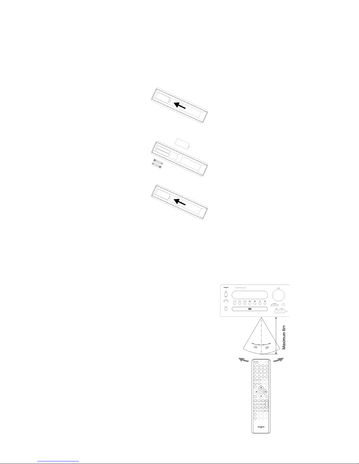
1 Remove the battery cover as illustrated.
2 Position two batteries of the type AAA/R03/UM4 in the battery compartment. Make sure that the
orientation of the batteries is correct (see drawing at bottom).
3 Replace the battery cover.
- Do not mix new and old batteries and do not use different types of batteries.
- If the remote control is not used for prolonged periods, remove the batteries from the remote control to
avoid corrosion.
Using the remote control
Direct the remote control at the sensor on the front panel of the unit. When the remote control signal is
received, the unit reacts accordingly. The remote control works within a range of 6 meters.
- Sometimes the remote control does not work well in strong
light. You may have to move the unit if it is a problem.
- Malfunction may occur if other remote controls are used
near the unit.
- Do not place any objects on the remote control, as the
batteries may become flat if a key is depressed constantly.
- Make sure that there are no obstacles between remote
control and unit.
- Do not position the unit behind tinted glass as it may reduce
the maximum range of the remote control.
Page 17
17
CONNECTION AF SPEAKERS
Before Connection
Before connection turn off the power of all the equipment.
Read instructions of each component you intend to connect to this unit.
- Be sure to insert each plug securely. To prevent hum and noise, do not bundle the interconnection leads
with power cord or speaker leads.
Speaker Connections
To avoid damaging the speakers with a sudden high-level signal, be sure to switch the power off before
connecting the speakers.
- Check the impedance of your speakers.
Connect speaker with an impedance between 8 and 4 ohms. The amplifier's colored speaker terminals
are the + (positive) terminals and the black terminals are the (negative) terminals.
- The + side of the speaker cable is marked to make it distinguishable from the side of the cable. Connect
this marked side to the colored + terminals and the unmarked side is the black terminal.
- Prepare the speaker cords for connection by stripping off approximately 10 mm or less (no more as this
could cause a short-circuit) of the outer insulation. Twist the wires tightly together so that they are not
straggly.
How to connect
Colored: positive (+)
Black: negative (-)
1. Unscrew the knob
2. Insert the speaker cable.
3. Tighten the knob and secure the cable.
Page 18
18
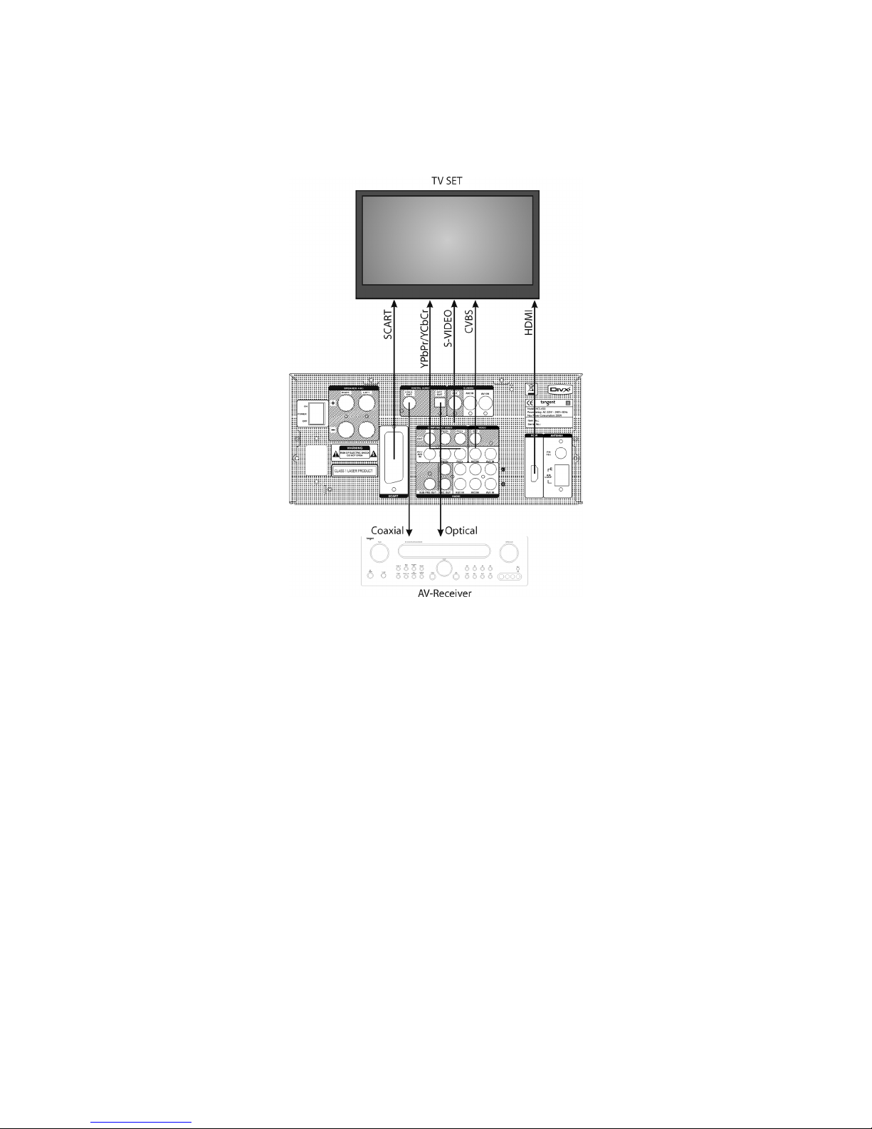
CONNECTION TO TV SET AND DIGITAL OUTPUTS
It is possible to connect the MCS-650 to the TV set in several different ways, depending on what kind of video
input connections your TV set features.
Scart (Sound and picture)
Only one cable is needed to connect to the TV set. This connection enables you to get CVBS and RGB picture
to you TV set. To get RGB picture through the Scart cable, you must set the Video output to RGB in the setup
menu.
Please notice that the sound output in the Scart connecter is volume regulated.
Component video (YPbPr/YCbCr) (Only picture, no sound)
To use the component video output, you must connect all three cables (Y,Cb,Cr/Y,Pb,Pr) in the correct order.
To get component video picture to your TV set, you must set the Video output to YUV in the setup menu. It is
active as standard. When using the component video connection you have the ability of using progressive
scan. To activate progressive scan press the P.SCAN button on the remote. If your picture distorts or
disappears when running progressive scan, press the P.SCAN button once again, to change back to
Interlaced scan.
Note: Progressive scan is only available on component video.
S-Video (Only picture, no sound)
Connect this output to your TV set through a S-Video cable. No adjustments in the setup menu is needed.
Page 19

19
Composite video (CVBS) (Only picture, no sound)
Connect this output to your TV set through a RCA Video cable. No adjustments in the setup menu is needed.
HDMI (Digital sound and picture)
Connect this output to your TV set for the best picture available from your MCS-650 through a HDMI cable.
The HDMI output features the following picture resolution: 480p (60Hz), 720p (60Hz), 1080i (60Hz), 576p
(50Hz), 720p (50Hz), 1080i (50Hz). The picture resolution can be adjusted in the setup menu. The digital
sound through the HDMI can be set to either SPDIF or PCM, depending on your TV set. The audio output in
the HDMI connection can be adjusted in the setup menu.
Please notice that not all TV sets features all of these connections. Make sure your TV set is compatible with
the connection type you have chosen.
Optical and Coaxial outputs
It is possible to connect the MCS-650 to a digital surround receiver or processor. This will give you the ability
to upgrade the sound experience from your MCS-650. The unit has both an optical and a coaxial digital output.
These output must be turned on tin the setup menu in order to work. Please see the description of SPDIF
setup for reference.
Page 20
20
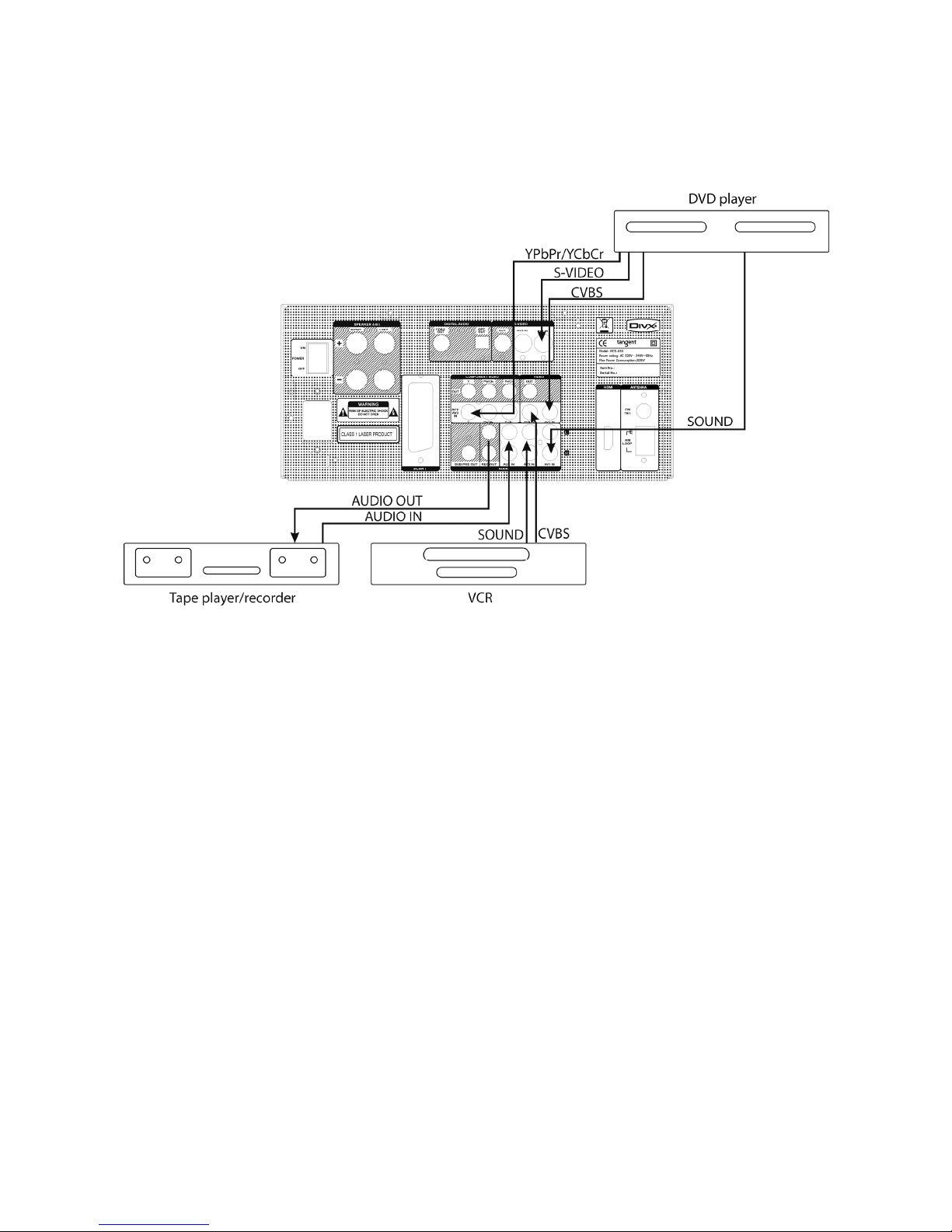
Rear panel inputs
The rear panel has one analog stereo auxiliary input/output (AUX) and two AV inputs.
- The AUX connection contains an analog stereo line input and an analog stereo line output (REC OUT)
Use this input to connect a tape recorder or similar products. Connect to source equipment using phono
cables (stereo 2RCA-2RCA). Choose the AUX input by pressing the AUX button on the remote.
- The AV1 and AV2 inputs both contains an analog stereo input, a composite video input (CVBS), a S-
video input and a component video input.
Choose the AV1 or AV2 inputs by pressing the AV1 or AV2/TV button on the remote. Please notice that
if the AV2/TV button is pressed twice, the sound and picture from the TV set will be played instead of the
sound and picture from the AV2 input.
Note: The AV1 and AV2 inputs share the component video input. That means only one source can be
connected to the MCS-650 through component video in. Also please notice that if you connect the AV1
or AV2 through the component video input, you must connect your TV set via the component video
output.
Note: Do not plug in the mains power lead or turn on the unit before all connections have been made.
Page 21
21
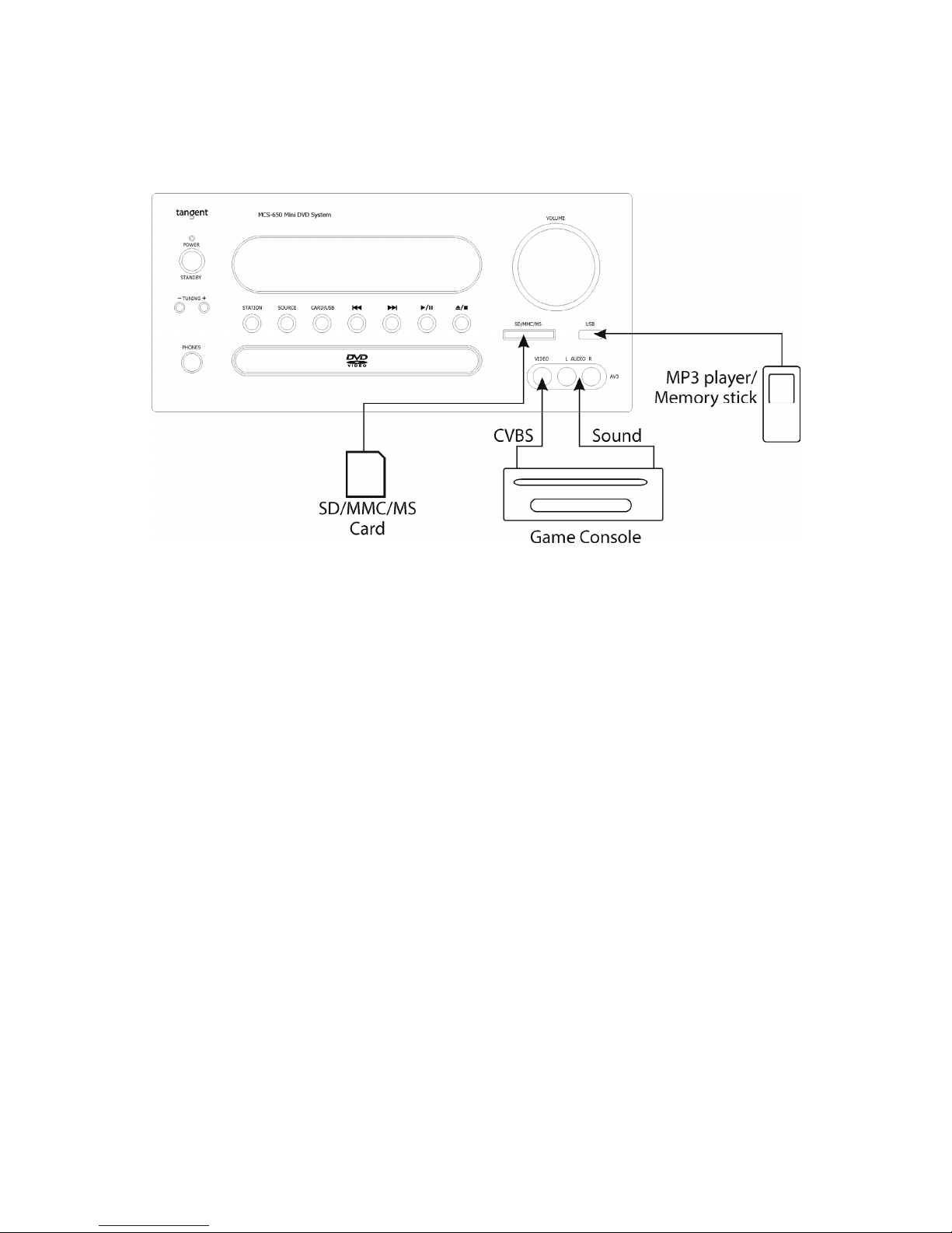
FRONT PANEL INPUTS
The front panel has three inputs: A card reader, a USB input an a AV input. These inputs are intended for
temporary and easy connections.
- The card reader enables you to insert your memory card from you camera or cell phone, to play music
or see pictures. You can browse the files of the connected source vi the TV set you have connected the
MCS-650 through. Please notice that the card reader is compatible with SD, MMC and MS card.
- The USB input enables you to connect your MP3 player or Memory stick to the unit, to play music or see
pictures. You can browse the files of the connected source vi the TV set you have connected the MCS-
650 through. Please notice that the USB input on the front panel is not iPod compatible.
- The AV3 input on the front panel contains an analog stereo input and a CVBS video input. This enables
to connect a gaming console or camcorder very easily. The AV3 input is a standard 3 RCA input, that
should be connected the same way as the inputs on the rear panel.
Choose the wanted input source by pressing the button on the remote that fits the wanted input.
Note: Do not plug in the mains power lead or turn on the unit before all connections have been made.
Page 22
22
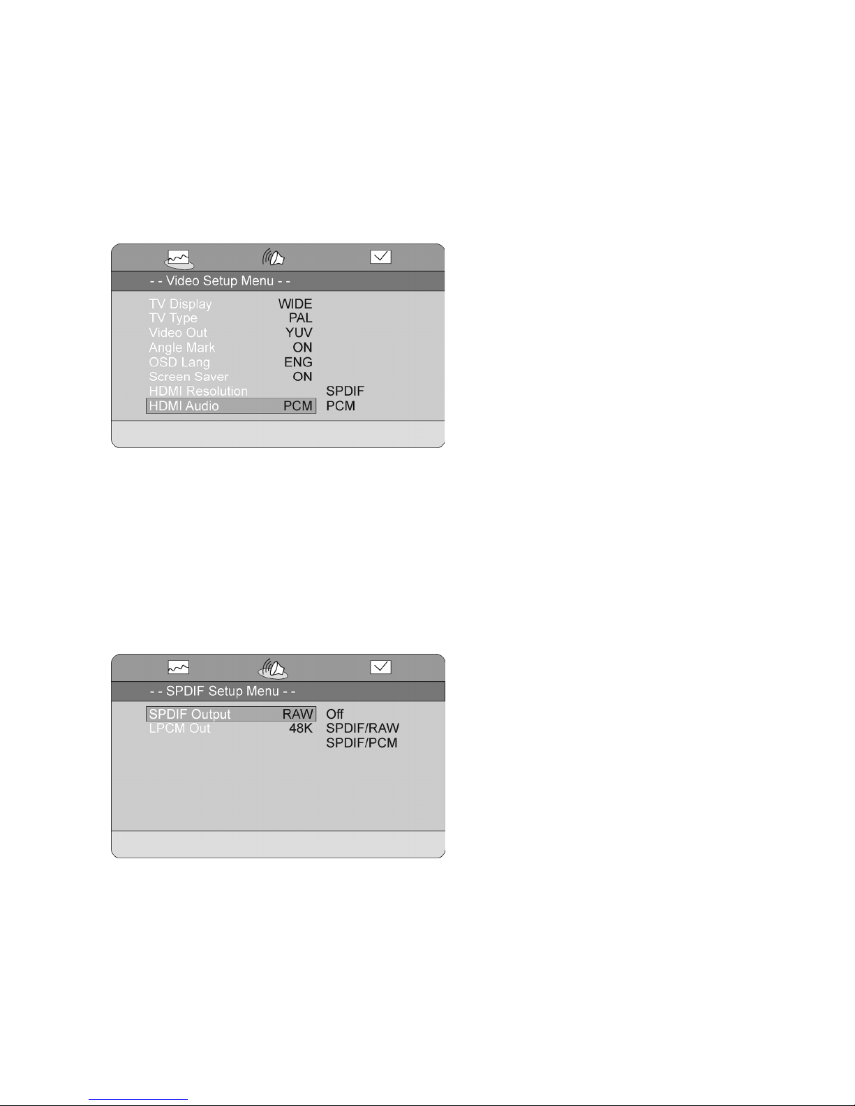
THE SETUP MENU
This unit features an On Screen Displayed setup menu.
Here you can make adjustments in the different setting this unit features.
Video Setup
The video setup enables you to make adjustments regarding the video appearance.
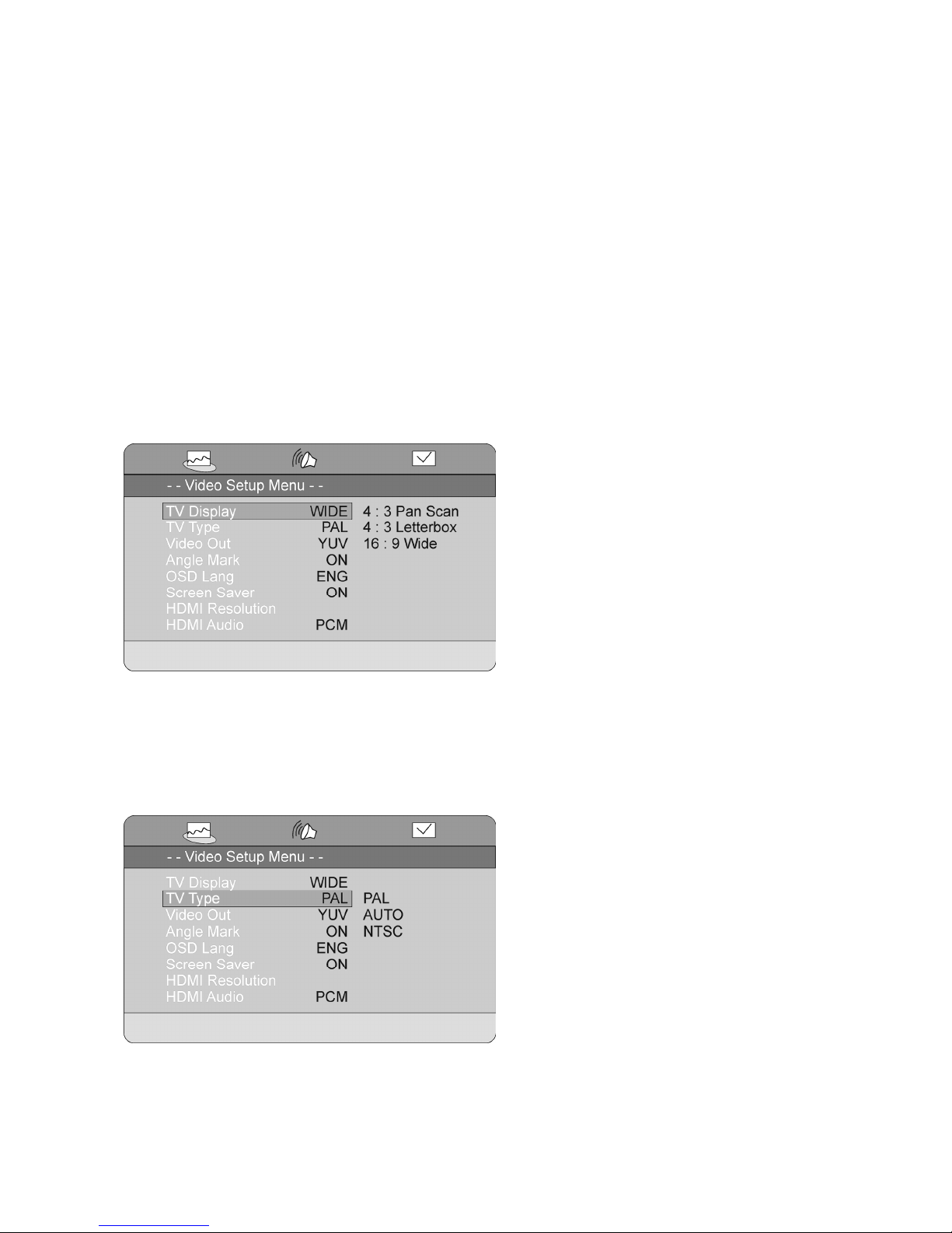
TV Display
Here you can set the perspective of your TV set.
4:3 Pan Scan: This setting will make sure every picture fits your 4:3 TV set. It will cut the picture to make it fit
your screen perfectly.
4:3 Letterbox: This setting will show 4:3 pictures on your screen normally and make a black bar in the top and
bottom of the screen when showing 16:9 pictures.
16:9 Wide: This setting will fit the pictures to match your widescreen TV.
TV Type
Here you can adjust the TV system to match your setup.
PAL: Standard European setup
AUTO: This setting should make sure the picture is displayed on most TV sets.
NTSC: Standard American TV system
Note: This setting is disabled when the HDMI output is activated.
Page 23
23
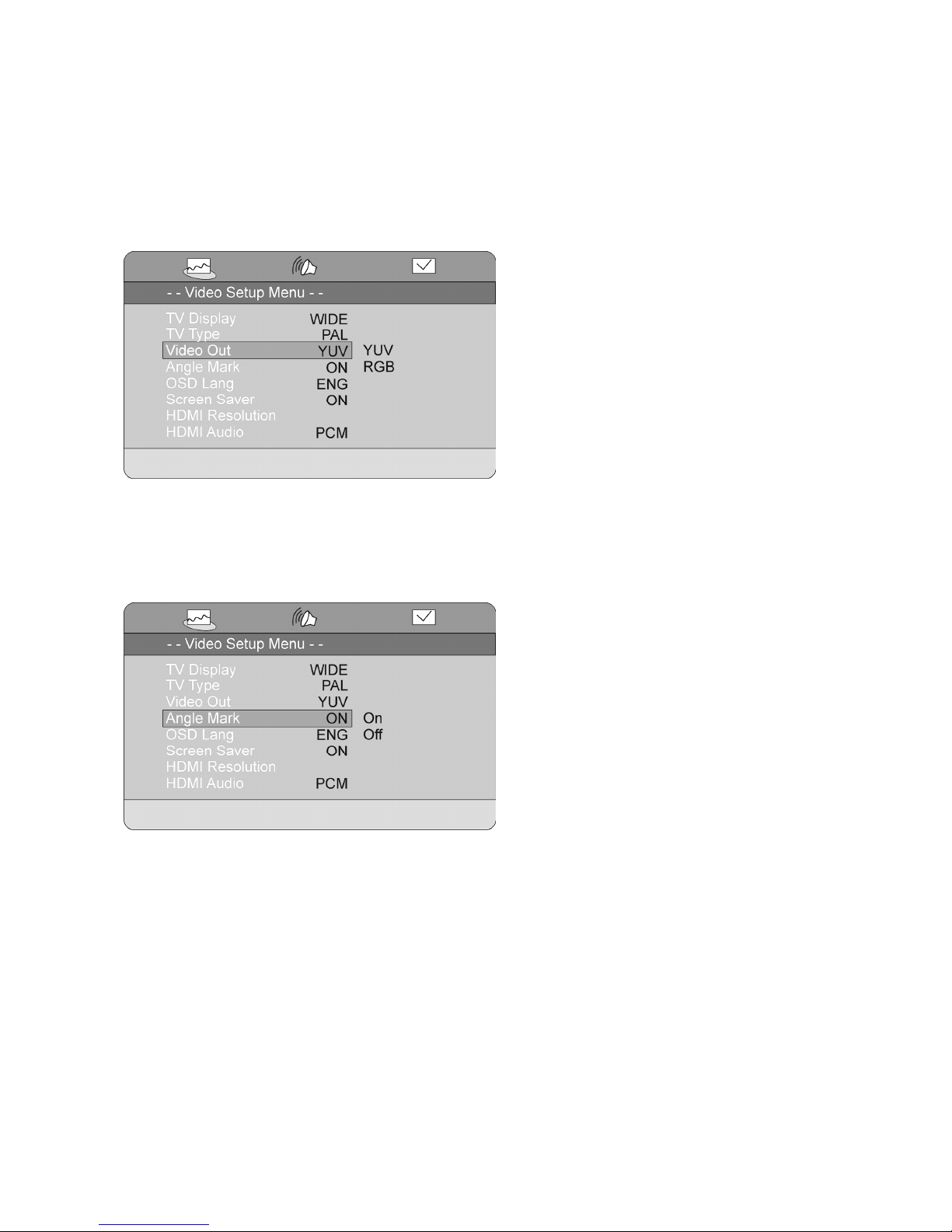
Video Out
Here you can adjust the video output settings to match your setup.
YUV: Activates the component video output. You can change between progressive scan and interlaced scan
by pressing the P.SCAN button on the remote.
RGB: Activates the RGB video output in the Scart connecter.
Note: This setting is disabled when the HDMI output is activated.
Angle Mark
Some DVD movies are recorded in multiple angles.
The Angle Mark feature enables the MCS-650 to tell you if more than one angle is available. When the Angle
Mark is set to ON, a small icon in the shape of a camcorder is shown on the screen. When Angle Mark is set
to OFF, this icon will not be shown.
Page 24
24
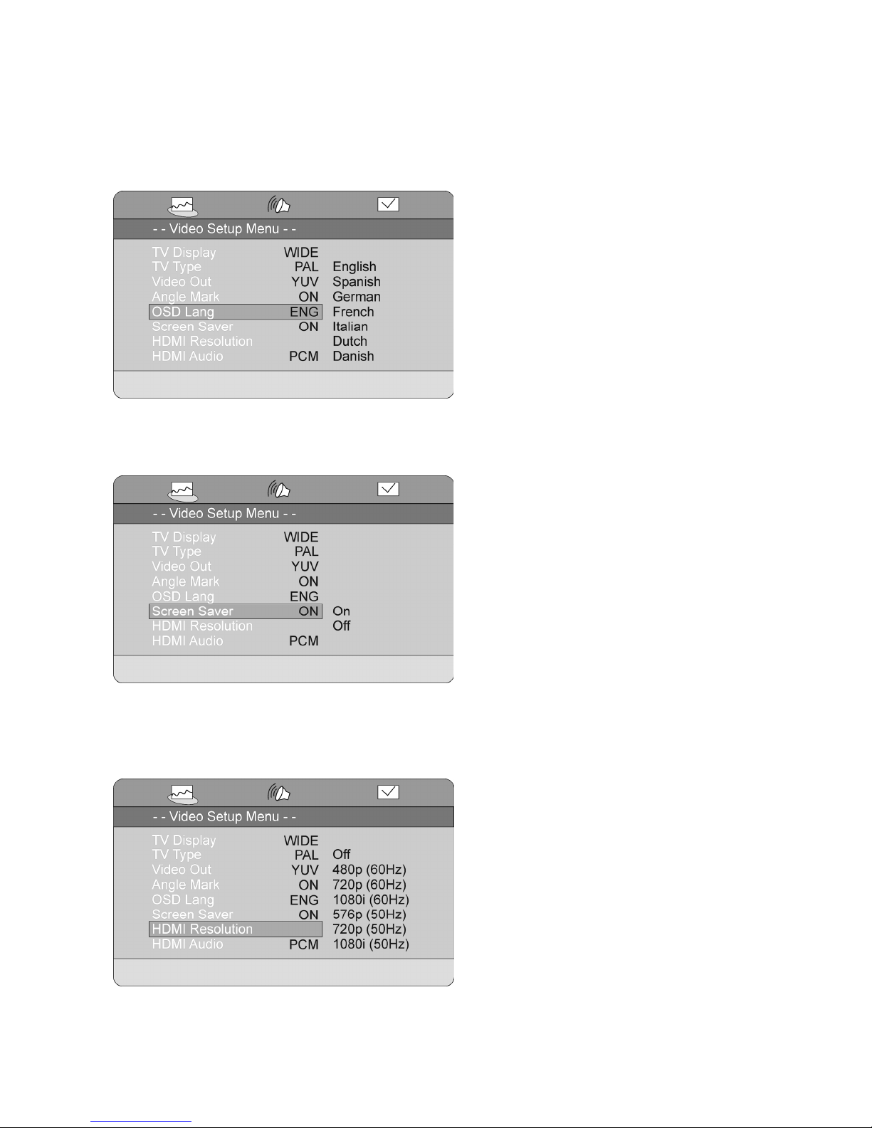
OSD Language
Here you can change the language of the setup menu and other messages shown on the screen.
Note: The languages available in this menu can vary.
Screen Saver
This function will start a screen saver similar to the one known from a computer after approximately
60seconds. You can choose between ON and OFF.
HDMI Resolution
Here you can set the resolution of the HDMI output. Choose between:
Off, 480p(60Hz), 720p(60Hz), 1080i(60Hz), 576p(50Hz), 720p(50Hz), 1080i(50Hz).
Note: Please make sure the HDMI output setting matches the specifications of your screen.
Page 25
25
HDMI Audio
Here you set the digital audio output in the HDMI connecter. You can choose between SPDIF and PCM.
Please notice that this setting must match the specifications of your system.
PCM: The standard setting is PCM which matches most TV sets. The PCM setting only enables stereo sound
in the HDMI connecter.
SPDIF: The SPDIF setting enables multi channel sound in the HDMI connecter. This feature is used if you are
connecting the HDMI output of the MCS-650 to a surround receiver or surround processor.
Audio Setup
The Audio setup enables you to make adjustments on the two digital audio outputs (Optical and Coaxial) on
the rear panel of the MCS-650.
SPDIF Output
Here you can adjust the digital outputs on the rear panel.
Off: Turns off the digital outputs
SPDIF/RAW: This setting makes sure the data in the digital outputs are exactly the same as the data on the
source playing.
SPDIF/PCM: This setting limits the sampling rate of the digital output to PCM (Stereo)
Page 26

26
LPCM Out
This setting is only available when the SPDIF output is set to PCM. (See the description above)
Here you can set the limitation of the digital output.
48KHz: Sets the down sampling to 48KHz
96KHz: Sets the down sampling to 96KHz
Note: When this feature is active, some audio track are not reproduced correctly.
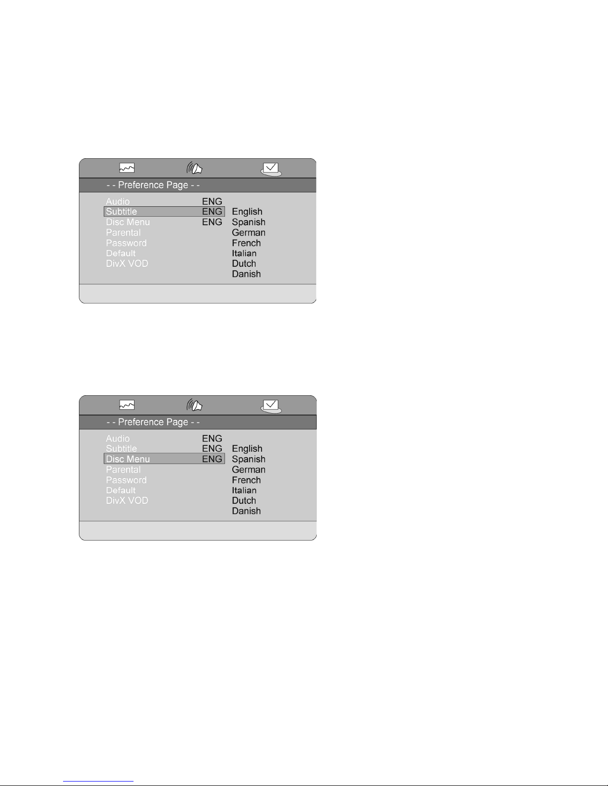
Preference Setup
In this menu you can make the most basic settings of the units DVD and DivX functions
Audio
This setting makes you able to set a preferred Audio language for playback of a DVD disc.
If the setting is set to e.g. German, the German audio track of a DVD disc will be selected automatically if
available.
Note: This feature is not available on all DVD discs.
Page 27
27
Subtitle
This setting makes you able to set a preferred subtitle language displayed during playback of a DVD disc.
If the setting is set to eg. German, the German subtitles of a DVD disc will be selected automatically if
available.
Note: This feature is not available on all DVD discs.
Disc Menu
This setting makes you able to set a preferred disc menu language for playback of a DVD disc.
If the setting is set to eg. German, the German disc menu of a DVD disc will be selected automatically if
available.
Note: This feature is not available on all DVD discs.
Page 28

28
Parental
This feature allows you to restrict the viewing of certain materials that may not be suitable for younger
members of the house. Please notice that in order to make adjustments in this menu, you are required to type
the password. See the next paragraph for further explanation to this.
The system is based on the rating information encoded on a DVD that classifies materials into 8 levels roughly
corresponding to the Motion Picture Association of America voluntary ratings system.
Note: Not all DVDs contains this information and will therefore not be affected by this setting.
Password
Here you can change the password required for making changes in the Parental settings.
Note: The default password is 1234
Page 29

29
Default
Here you can reset all the setting of the MCS-650 to the factory defaults.
Note: All video, audio, tuner, etc. settings will be lost if a reset is performed.
DivX VOD
Here you can require an 8 digit code for rental of DivX files on the internet etc.
Please visit www.DivX.com for further instructions.
USING THE RADIO
Connecting an antenna
Before you can start listening to radio stations, you must connect an antenna to the MCS-650.
The receiver is able to receive both FM and AM radio. It is therefore possible to connect both an AM and a FM
antenna to the receiver.
1. FM antenna input. Connect the included FM antenna whip to this input. Adjust the position of the
antenna whip until optimum reception is achieved. If an satisfying signal cannot be received with the
included antenna whip, an external FM antenna must be connected instead. Make sure the cable used
for this is 75 ohms coaxial antenna cable. The input can also be used for connection to an antenna
cable network if available.
Page 30

30
2. AM antenna input. Connect the included AM loop antenna to this input. Move the antenna until optimum
reception is achieved.
Note:
It is strongly recommended to use outdoor external antenna to achieve the optimum antenna signal.
Tuning in channels
To tune in channels on the MCS-650, you have three options:
- APS (Auto Program Scan)
- Automatic frequency search
- Manual frequency search
APS (Auto Program Scan)
Press the APS button on the remote. The receiver will automatically search the entire band for channels,
and store them as they come. This is the easiest way to tune in radio channels. The downside to this is
that the channels will be stored in the order they have been found in.
Automatic frequency search
Press the AUTO button on the remote. The display will show AUTO ON. Press and hold the TUNING +
or TUNING - button on the remote for 1 second. The unit will automatically scan the frequency up or
down, until a radio station is found. You can also turn the TUNING knob on the front panel of the
receiver to scan up or down in frequency.
Manual frequency search
To search manually in the frequencies, press the the AUTO button on the remote. Make sure the display
shows AUTO OFF. Then press the TUNING +/- button on the remote to step up or down in frequency. If
you press and hold the TUNING +/- button on the remote, the receiver will keep stepping up or down in
frequency, until you let go of the button. You can also turn the TUNING button on the front panel of the
receiver to manually tune up or down in frequency.
To store a frequency to a preset after automatic or manual searching, press the MEM button on the remote
once. A number will start to flash in the display. Then press the preferred preset number you whish to store the
frequency to. The frequency has now been stored to a preset after your choice.
Use the Arrow Up and Arrow Down buttons on the remote to change between the stored stations.
If your antenna signal is too weak, you might experience some noise when listening to radio in stereo. You can
some times remove this noise by switching to mono. This is done by pressing the ST/MO button on the
remote.
RDS (Radio Data System)
RDS is a method for the transmission of additional information from Radio Stations. It is only available in FM
mode. For example, the name of the radio station, the name of the program or the type of program can be
shown on the display. It functions only when the broadcasting station has the RDS transmission and the signal
is strong enough.
Press “DISPLAY” on remote control to display the RDS information. RDS contains the following information:
Page 31

31
PS (Program Service name)
PTY (Program TYpe)
CT (Clock Time)
RT (Radio Text)
A) PS (Program Service Name)
Press the DISPLAY button on the remote until PS appears. The current stations name will be shown.
Note: NO PS will be shown if the signal from the radio station is not strong enough or no such service is
available.
B) PTY (Program Type)
Press the DISPLAY button on the remote until PTY appears. The current type of the program will be
shown.
Note: NO PTY will be shown if the signal from the radio station is not strong enough or no such service is
available.
C) CT (Clock - Time)
Press the DISPLAY button on the remote until WAITING CT will appear. The current time from the radio
Station will be shown, e.g. 15:30
Note:
1. The Clock - Time will be only transmitted from the radio stations once a minute, so you need to wait
for less than 1 minute to see the time.
2. NO CT will be shown if the signal from the radio station is not strong enough or no such service is
available.
D) RT (Radiotext)
Press the DISPLAY button on the remote until RT appears. The text message will start to scroll across the
display.
Note: NO RT will be shown if the signal from the radio station is not strong enough or no such service is
available.
PTY SEARCH (Program Type Search)
1. Press the PTY SEARCH button on the remote, PTY SEL will flash on the display.
2. Press the TUNING + /- on the remote to choose the program type, for example, NEWS, SPORT, etc.
3. Press the PTY SEARCH button again to choose the program type shown in the display. PTY SRH will be
shown on the display when a search is going on.
4. When the type of program is tuned in, it will stop searching, otherwise, NO FOUND will appear in the
display.
Page 32

32
Troubleshooting
If you have a problem with DVD player, check this list for a possible solution before calling for service. Some
simple or minor problems can be solved by yourself. If the unit works abnormally continuously or the unit has
been physically damaged, turn off the power and disconnect the AC power plug, consult qualified person such
as dealer for service.
Symptom / Remedy
No sound or Distorted sound
- Confirm the power cord plug is well connected.
- Make sure the setting of TV or other AV equipment is proper.
- Make sure the TV or the amplifier is under normal operation.
- As you use the headphones, make sure the headphone is well connected with the jack and the volume
switch (phone level) is turned to proper level
- No sound is heard during still picture (pause) or slow motion play.
No picture
- Make sure the equipment is well connected.
- Make sure the input setting for the TV is “Video” or “AV”
- Make sure the specifications of the TV is according to the settings of the unit.
- Make sure TV is under normal operation.
- Make sure the color system is set at the proper mode (NTSC/PAL)
Picture breakdown
- Make sure there is no significant damage on the disc
- The disc may be dirty, clean it and re-start again
Does not play
- Make sure the disc is well installed with the label facing at the top.
- The disc may be dirty and require cleaning
- The player will be affected by moist disc or by condensation, keep the disc dry and wait about 1 or 2
hours to allow the player to dry out.
No operation can be performed with the remote control
- Check the batteries are installed with the correct polarities (+ & -)
- Make sure the batteries are in good condition and not depleted. If yes, replace the new ones.
- Make sure the remote is pointing at the sensor
- Remove the obstacles between the player and the remote
No surround sound
- Choose the correct setup of the speaker setting which matches with your stereo system
- Check speaker connections
- Check the sources materials—if mono, sound may only come out of the centre output.
- If 2-channel DVD model, you will require a Pro Logic decoder or Dolby Digital decoder to reproduce the
surround output.
No 4:3 (16:9) picture
- Choose the correct setup “TV SCREEN” item that matches with your TV type.
Remark: Abnormal functioning of this unit may be caused by static electricity or other external interference. To
restore normal operation, unplug the AC cord and then plug it in again or switch off and on the player again.
Page 33

33
Specifications
Audio Section
Rated Power Output: 2 x 40 W 8 ohm
2 x 60 W 4 ohm
Total Harmonic Distortion: Less than 0.2% rated power output
Line Input
Input Sensitivity/Impedance: 200 mV /47kohm
Frequency Response: 20 Hz - 20 kHz +0.5 / -3 dB
Tone Control Range:
BASS: ±10dB
TREBLE: ±10dB
Signal-to-noise Ratio: 70 dB CCIR/ARM
Subwoofer Output
Rated Output/Impedance: 2 V / 2.2Kohm
Frequency Response: 10 Hz - 120 Hz ± 3 dB
FM Tuner Section
Frequency Range: 87.5-108 MHz
Sensitivity: 14dB (5uV)
Antenna Terminal: 75 ohm (unbalanced)
MW Tuner Section
Frequency Range: 522 - 1629 kHz (Europe) 9 kHz step
Sensitivity: 60 dB / M
Single-to-noise Ratio: 50 dB
Antenna: Loop Antenna
Video Section
Inputs: CVBS, S-Video and Component video
Outputs: HDMI, CVBS, S-Video, Component video and RGB (Scart)
Level/Impedance: 1 Vp-p / 75ohm
HDMI Resolutions 480p, 720p, 1080i (60Hz)
576p, 720p, 1080i (50Hz)
Progressive scan Via Component video
Compatible discs:
DVD Video, DVD+ r/rw, DVD- r/rw
CD, CD-r/rw.
VCD, S-VCD
MP3 disc, WMA disc, JPEG
DivX 3.xx, 4.xx, 5.xx
Compatible digital sources USB input for audio and video
Card reader for SD, MMC, MS
Digital audio outputs: Optical, Coaxial
General
Power Requirements:
Power Supply: AC220V –240V~ 50/60Hz
Power Consumption: 200 Watts
Dimensions: 275(W) x 135(H) x 350(D) mm
Net Weight: 5.8Kg
*Design and specifications are subject to change without notice.
Page 34

34
Page 35

35
Page 36

36
Service hotline +45 9641 1599
For further information, please visit our website:
Item No.: 40597
 Loading...