


T40

Installation and User Guide

ii
Copyright
©
2006 Tandberg Data ASA
The information contained in this document is subject to change without notice.
This document contains proprietary information which is protected by copyright. All rights are
reserved. No part of
this document may be reproduced, modified, distributed, or translated to another language without prior written
consent of Tandberg Data.
Tandberg Data ASA
Kjelsåsveien 161
P.O. Box 134 Kjelsås
N-
0411 Oslo, Norway
Tel: +47 22 18 90 90
Fax: +47 22 18 95 50
www.tandbergdata.com
This document may describe designs for which patents are pending, or have been granted. By publishing this
information, Tandberg Data conveys no license under any pate
nt or any other right.
Tandberg Data shall not be liable for errors contained herein or for incidental or consequential damages
(including lost profits) in connection with the furnishing, performance or use of this material whether based on
warranty, cont
ract, or other legal theory. Tandberg Data makes no representation or warranty with respect to the
contents of this document and specifically disclaims any implied warranties of merchantability or fitness for any
particular purpose. Further, Tandberg Data
reserves the right to revise or change this document without
obligation on the part of Tandberg Data to notify any person or organization of such revision or change.
Every effort has been made to acknowledge trademarks and their owners. All trademarks wit
hin this document
are the property of their respective owners. Trademarked names are used solely for identification or exemplary
purposes,
and
any omissions are unintentional.
Published:
January 2007
Part No.: 433599
-
02

StorageLibrary Installation and User Guide
iii
Table of Contents
1 About This Guide
1
Waste Electrical and Electronic Equipment Directive
..............................................................................
1
Product Model Number
.............................................................................................................................
1
Explanation of Symbols and Notes
..........................................................................................................
1
Other Documents You Might Need
..........................................................................................................
2
Getting More Information or Help
.............................................................................................................
2
2 Product Overview
3
Product Descri
ption
..................................................................................................................................
3
Tape Drive Support
............................................................................................................................
3
Data Transfer Rates
...........................................................................................................................
4
Magazines
..........................................................................................................................................
4
Front Panel
.........................................................................................................................................
4
Rear Panel
.........................................................................................................................................
5
Library Features
.......................................................................................................................................
6
Operator Interfaces
............................................................................................................................
6
ADI Bridging and LUN
........................................................................................................................
6
Partitions
............................................................................................................................................
7
Control Path
.......................................................................................................................................
7
I/E Station
...........................................................................................................................................
7
Simple Network Management Protocol (SNMP)
................................................................................
7
Capacity on Demand (COD)
..............................................................................................................
7
Browser Requirements
......................................................................................................................
8
3 Unpacking the St
orageLibrary
9
Finding a Location for the StorageLibrary
................................................................................................
9
Unpack
.....................................................................................................................................................
9
4 Installing the Library
11
Remove the Transport Locking Screws
................................................................................................
.
11
Mounting the StorageLibrary in a Rack
..................................................................................................
12
Mounting the Rack mount Ears
.......................................................................................................
13
Installing the Rails in a Rack
............................................................................................................
14
Instal
ling the Left Rail Assembly
......................................................................................................
14
Installing the Right Rail Assembly
...................................................................................................
14
Mounting the StorageLibrary to the Rack
........................................................................................
15
Installing the Library
...............................................................................................................................
16
Connecting Library Cables (SCSI)
...................................................................................................
16
Connecting Li
brary Cables (Fibre Channel)
....................................................................................
17

iv
Contents
System Power
-
on
.............................................................................................................................
18
Labeling Cartridges for the Barcode Reader
...................................................................................
19
5 Information about the Operator Interfaces
21
Front Panel Interface (FPI)
.....................................................................................................................
21
Scroll Funct
ion
................................................................................................................................
.
21
Remote Management Interface
..............................................................................................................
22
Menu Trees
............................................................................................................................................
22
Home Scre
en
..........................................................................................................................................
28
Operator Privileges
................................................................................................................................
.
29
Words Commonly Used on the FPI and RMI
.........................................................................................
30
6 Configuring the Library
33
About the Setup Wizard
..........................................................................................................................
33
Using the Default Administrative User Account (Administrator)
......................................................
33
Using the Setup Wizard
...................................................................................................................
34
Setup Wizard Tasks
.........................................................................................................................
34
Configuri
ng Network Settings
.................................................................................................................
35
Remote Access
................................................................................................................................
36
Applying a License Key
..........................................................................................................................
36
Configuring I/E Slots
...............................................................................................................................
37
Configuring Cleaning Slots
.....................................................................................................................
37
Configuring Partitions
.............................................................................................................................
38
Creating Partitions
...........................................................................................................................
38
Reconfigure Partitions
......................................................................................................................
39
Changing Partition Modes
................................................................................................................
39
Setting Drive ID
......................................................................................................................................
40
Modifying the Control Path
.....................................................................................................................
40
Configuring Autoclean
............................................................................................................................
41
Configuring FPI Password
......................................................................................................................
41
Configuring RMI Password
.....................................................................................................................
42
Configuring Men
u Timeout
.....................................................................................................................
42
Setting Date and Time
............................................................................................................................
42
Configuring Barcode Scan
.....................................................................................................................
42
Configuring Audible Alarm
......................................................................................................................
43
Configuring SNMP
..................................................................................................................................
43
Configuring E
-
mail Notification
...............................................................................................................
43
7 Running the Library
45
Logging In
...............................................................................................................................................
45
Logging Out
............................................................................................................................................
45
Importing Cartridges
...............................................................................................................................
45
Importing Cartridges via I/E Slot
......................................................................................................
46
Import Cartridges via Bulk Loading of Magazi
nes
...........................................................................
47
Exporting Cartridges
...............................................................................................................................
47
Loading to Tape Drives
..........................................................................................................................
47
Unlo
ading from Tape Drives
...................................................................................................................
47
Cleaning Tape Drives
.............................................................................................................................
48
Importing Cleaning Media
................................................................................................................
48
Cleaning Media Handling
.................................................................................................................
48
Exporting Cleaning Media
................................................................................................................
48
Autoclean
.........................................................................................................................................
48
Manual Clean
...................................................................................................................................
49
Taking the Library Online/Offline
............................................................................................................
49
Taking a Library Online
....................................................................................................................
49
Taking a Library Offline
....................................................................................................................
49

StorageLibrary Installation and User Guide
v
Magazine Handling
................................................................................................................................
.
49
Standby Functionality
.............................................................................................................................
52
8 Getting Status and Information
53
Viewing Library Settings
.........................................................................................................................
53
Viewin
g Partitions/Drive Settings
...........................................................................................................
53
Viewing Network Settings
.......................................................................................................................
54
Viewing Statistics
....................................................................................................................................
54
Viewing Log
............................................................................................................................................
55
9 Adding, Removing and Replacing
57
Power Supply Unit
..................................................................................................................................
57
Removing and Replacing a Power Supply
......................................................................................
57
Tape Drive Unit
.......................................................................................................................................
58
Adding a Tape Drive
........................................................................................................................
58
Permanently Removing a Tape Drive
..............................................................................................
59
Removing and Replacing a Tape Drive
...........................................................................................
59
10 Updating Firmware
61
Updating Library Firmware
.....................................................................................................................
61
Updating Drive Firmware
........................................................................................................................
62
11 Working With Cartridges and Barcodes
65
Handling Cartridges Properly
.................................................................................................................
65
Write
-
Protecting Cartridges
....................................................................................................................
66
Barcode Requirements
...........................................................................................................................
66
Installing Barcode Labels
.......................................................................................................................
66
12 Tro
ubleshooting
67
About RAS Tickets
................................................................................................................................
.
67
Viewing RAS Tickets
........................................................................................................................
67
C
losing RAS Tickets
........................................................................................................................
68
Supported RAS Tickets
....................................................................................................................
68
Interpreting LEDs
....................................................................................................................................
70
The Maintenance Menus
.................................................................................................................
71
The Diagnostics Menu
.....................................................................................................................
71
Verifying Hardware
................................................................................................................................
.
71
Software Checking
................................................................................................................................
.
72
Verifying Recent Changes
......................................................................................................................
72
Troubleshooting Matrix
...........................................................................................................................
72
13 Shipping or Transporting StorageLibrary
79
Reinserting the Transport Locking Screws
.............................................................................................
79
Packi
ng the StorageLibrary
....................................................................................................................
80
14 Specifications
81
Library Dimensions
................................................................................................................................
.
82
Library Component Weights
...................................................................................................................
82
Power Requirements
..............................................................................................................................
83

vi
Contents
Climatic Specifications
............................................................................................................................
83
15 Safety and Regulatory Information
85
Safety Approvals
....................................................................................................................................
85
EMC Approvals
.......................................................................................................................................
85
Europe
..............................................................................................................................................
85
USA
..................................................................................................................................................
85
Japan
...............................................................................................................................................
86
Canada
.............................................................................................................................................
86
Conformity Declarations
.........................................................................................................................
86
Europe
..............................................................................................................................................
86
Australia
/New Zealand
.....................................................................................................................
86
16 Approved Drive Types
87

StorageLibrary Installation and User Guide
vii
Figures
Figure 1. Front Panel of the StorageLibrary
.............................................................................................
4
Figure 2. Rear Panel of the StorageLibrary with 1 Full
-
Height SCSI Drive Installed
...............................
5
Figure 3. Transport Locking Screws Marked
with Red Plastic Tabs
......................................................
11
Figure 4. Recommended Storage of Transport Locking Screws
...........................................................
12
Figure 5. Rackmounting Kit with Rackmoun
t Ears (Right figure)
...........................................................
13
Figure 6. Mounting the Rackmount Ears
................................................................................................
13
Figure 7. Rackmount Rail
.......................................................................................................................
14
Figure 9. StorageLibrary Mounted in a Rack, Front View
......................................................................
15
Figure 10. StorageLibrary Mounted in a Rack, Rear View
.....................................................................
16
Figure 11. StorageLibrary Cabling (SCSI)
..............................................................................................
16
Figure 12. StorageLibrary Cabling (Fibre Channel)
...............................................................................
18
Figure
13. Positioning of Barcode Label for LTO Cartridges
................................................................
.
19
Figure 14 Front Panel Interface Menu Tree
...........................................................................................
23
Figure 15 Remote Manageme
nt Interface Top Level Menu Tree
..........................................................
26
Figure 16. RMI Home Screen
.................................................................................................................
29
Figure 17. Map Menu
.............................................................................................................................
31
Figure 18. Removing the Magazine from the Library
.............................................................................
50
Figure 19. Gently Push the Cartridge into the Magazine Slot
................................................................
50
Figure 20. Push the Release Knob towards the Cartridge to Eject the Cartridge from the Slot
............
51
Figure 21. Push Magazine until it Clicks into Place
...............................................................................
51
Figure 22. The Release Tool Inserted into the Correct Hole on the Left Lower Magazine
....................
52
Figure 23. Replacing a Power Supply
....................................................................................................
58
Figure 24. Adding, Removing or Replacing a Tape Drive
......................................................................
60

viii
Contents
Tables
Table 1. Data Transfer Rates
...................................................................................................................
4
Table 2. Front Panel Interface Menu Structure
......................................................................................
24
Table 3. Remote Management Interface Menu Structure
......................................................................
27
Table 4. Commonly Used Words on FPI and RMI
.................................................................................
30
Table 5. Cartridge Present Symbols on FPI During Inventory and in the Maps Menu
..........................
30
Table 6. Supported RAS Tickets
Parameters and Priority
..................................................................
68
Table 7. Maintenance Menus
-
Item Name and Description
..................................................................
71
Table 8. Diagnostics Menu
-
Item Name and Description
......................................................................
71
Table 9. Troubleshooting Matrix
Power with Solution
.........................................................................
73
Table 10. Troubleshooting Matrix
Cartridge Movement with Solution
................................................
74
Table 11. Troubleshooting Matrix
Media with Solution
.......................................................................
75
Table 12. Troubleshooting Matrix
SCSI with Solution
.........................................................................
75
Table 13. Troubleshooting Matrix
Library Performance with Solution
................................................
76
Table 14. Troubleshooting Matrix
Cleaning with Solution
...................................................................
76
Table 15. Troubleshooting Matrix Write or Read Issues with Solution
...............................................
77
Table 16. Troubleshooting Matrix LED Error Messages with Solution
...................................................
77
Table 17. Troubleshooting Matrix Errors Displayed on Front Panel with Solution
..............................
77
Table 18. Troubleshooting Matrix
Remote Management with Solution
..............................................
78
Table 19. Troubleshooting Matrix
Forgot Password with Solution
......................................................
78
Table 20. Library Specification Summary
...............................................................................................
81
Table 21. Library Dimensions
.................................................................................................................
82
Table 22. Library Component Weight
.....................................................................................................
82
Table 23. Power Requirements
..............................................................................................................
83
Table 24. Temperature Range
...............................................................................................................
83
Table 25. Humidity Range
......................................................................................................................
83
Table 26. Altitude Range
........................................................................................................................
83

StorageLibrary Installation and User Guide
1
1 About This Guide
This guide contains information and instructions necessary for the normal operation and management
of the StorageLibrary T40. This guide is intended for anyone interested in learning about or anyone
that needs to know how to install, configure, and opera
te the StorageLibrary T40. Be aware that
Administrator level privileges are required to configure many of the features described in this guide.
Note
Be sure to read all operating instructions in this manual before operating this
product.
Waste Electrical and Electronic Equipment Directive
This product contains materials that are recyclable under the Waste Electrical and Electronic
Equipment (WEEE) directive of the European Union. This product should not be disposed of as
unsorted municipal waste.
Produ
ct Model Number
The Tandberg StorageLibrary T40 model number is as follows
: 1040
.
Explanation of Symbols and Notes
The following symbols appear throughout this document to highlight important information.
Caution
Indicates a situation that may cause pos
sible damage to equipment, loss of data,
or interference with other equipment.
Warning
Indicates a potentially hazardous situation which, if not avoided, could result in
death or bodily injury.
Note
Indicates information that helps you make better
use of your system.

2
About This G
uid
e
Other Documents You Might Need
The following documents are also available for this product. These documents can be found at
www.tandbergdata.com
:
SCSI
Functional Specification
,
StorageLibra
ry T40 (433489) provides the SCSI interface
specification for the Tandberg Data StorageLibrary T40.
Quick Installation Guide, StorageLibrary T40 (433559) gives you an overview of how to install the
library.
Customer Replaceable Unit (CRU) Tape Drive Inst
ruction:, StorageLibrary T40 (433601)
Customer Replaceable Unit (CRU) Power Supply Instruction:, StorageLibrary T40 (433602)
Getting More Information or Help
For further assistance please
visit our web at
www.tan
dbergdata.com
or contact these regional
locations:
International Headquarter
Tandberg Data ASA, Kjelsåsveien 161
P.O. Box 134 Kjelsås, N
-
0411 Oslo, Norway
e-
mail:
support@tandbergdata.com
Tel: +47 22 18 9
0 90, Fax: +47 22 18 95 50
Other locations
:
Europe
:
Tel.: 00800 826 323 74
-
(00800 TANDBERG)
e-
mail:
support
-
de@tandbergdata.com
Asia Pacific
:
Tel.: +65 6396 0786
email:
support@tandbergdata.com.sg
Americas
:
Toll Free: +1
800
392 2983
Tel.: +1
303 442 4333
e-
mail:
support
-
us@tandbergdata.com

StorageLibrary Installation and User Guide
3
2 Product Overview
Ta
ndberg
StorageLibrary
T40
is a compact tape cartridge library designed for secure, reliable,
unattended system backup. The library can be mounted in a 19 rack or used as a tabletop unit.
The
height of the
rack mount
version
is 4U.
The drive types supported by the
StorageL
ibrary are given in chapter
16
Approved Drive Type
s.
The
library has 40 ph
ysical tape
slots
installed.
The
StorageLibrary
has several features designed to increase the products ease of use and utility,
such as:
Four removable magazines allow easy management of data sets or archival storage. There are no
hidden
slots
.
A menu
-
dri
ven operator control panel interface with backlit LCD provides easy control for
configur
ation and diagnostic activities
.
Remote management to the library vi
a a remote management interface
.
Menu Wizards for simplified library configuration
.
Integrated
barco
de reader
.
Support for both SCSI/LVD and Fiber Channel Tape Drives
.
On
-
board Diagnostics for diagnostics and fault analysis
.
Standby functionality for power savings
.
Customer replaceable tape drives and powe
r supply
.
Customer upgradeable by adding tape dri
ves and cartridge
slot
s.
Caution
Review the C
aution at the beginning of
Unpacking
the
StorageLibrary
before you
power up the unit for the first time.
Product Description
Tape
D
ri
ve
S
upport
For additional specification information for this model,
see
Specifications
.
The drive types supported
by the StorageLibrary are given in chapter
16
Approved Drive Type
s.
The library supports 1
-
2 full
-
height drives
,
1-
4
half
-
height drives
and a combination of these
. The library s
upports both Fibre
4
Product Overview
Channel and SCSI tape drive interfaces within the same library. LTO Fibre Channel tape drives can
be directly attached to hosts or the SAN. LTO SCSI tape drives are attached directly to the host.
Tape drives are installed into tape drive
bay
s in the rear of the library. If a tape drive
bay
is empty, a
cover plate
covers the empty tape drive
bay
to prevent
dust
from entering the library.
Tape drives can
be installed in any available tape drive bay.
Data Transfer Rates
Table
1.
Data Transfer Rates
StorageLibrary
Model
Maximum Sustained Rate,
Native
Maximum Sustained Rate, Compressed
LTO
-
3 SCSI
80MB/s
160MB/s
LTO
-
3 FC
80MB/s
160MB/s
LTO
-
4 SCSI
120
MB
/s
240
MB
/s
LTO
-
4 FC
120MB/s 240MB/s
Magazines
The li
brary is equipped with four removable magazines
,
all accessible from the f
ront of the unit. The
lower
magazines hold 12 cartr
idges each and the two upper
magazines hold 8 cartridges each. There
are no hidden
slots
. To cool the library
,
there are air inlet
holes on the bezels. For easy removal of the
magazines, use handles on the sides of the bezels. For details on magazine handling, see the
section
Magazine Handling.
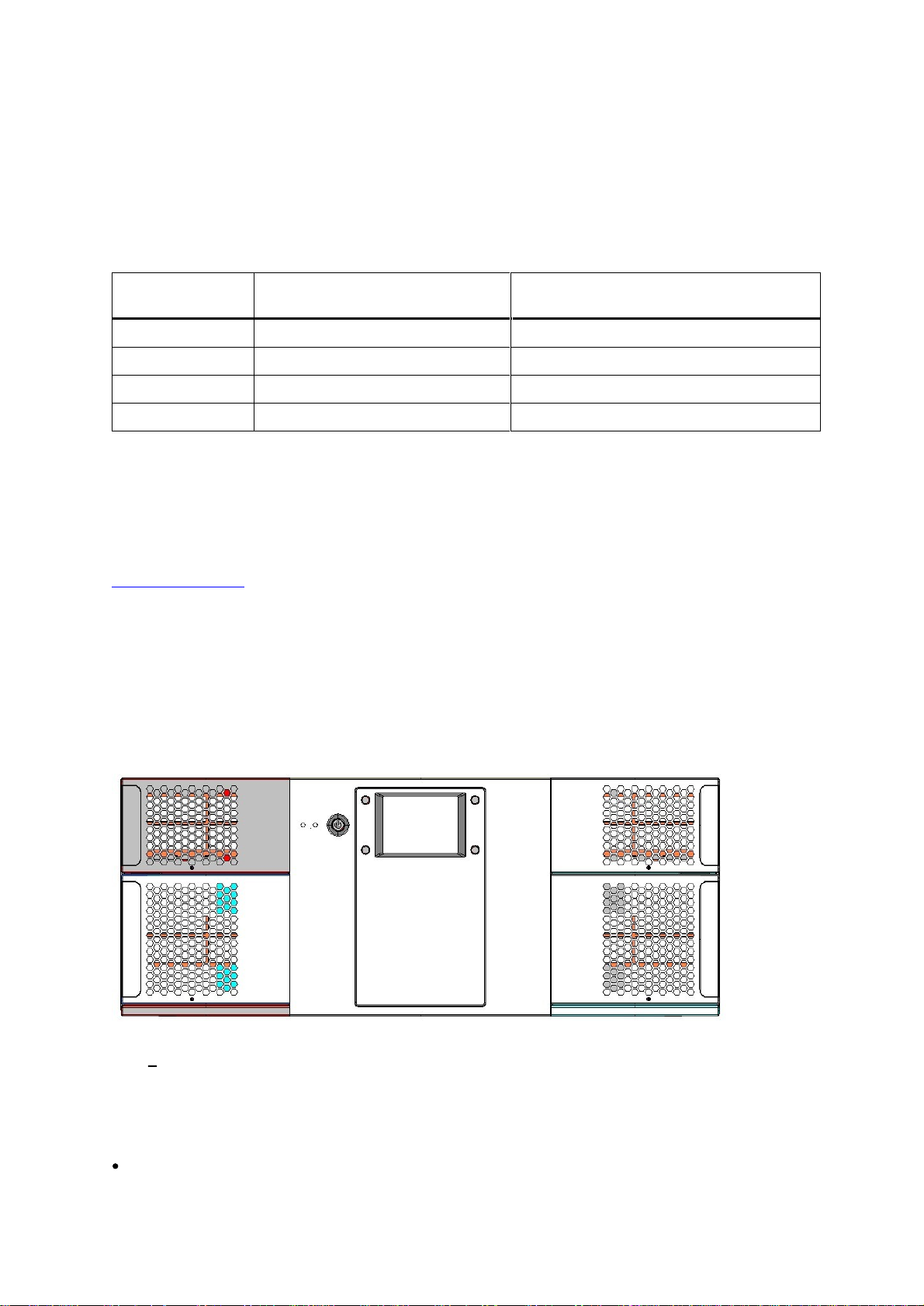
Front Panel
The Front Panel
includes the
Operator
control panel with LCD display, four control buttons, two LED
indicators and a standby switch. The bezels of the four magazines are also visible from the front.
Figure
1.
Front
Panel of t
he
StorageLibrary
LCD
L
iquid
C
rystal
D
isplay
The display is a backlit 12
8
x
68
, dot
-
matrix graphical display that can show 8 lines of 20 characters.
In various modes of operation, the display panel screens and control buttons allow you to do the
following:
Enter settin
gs
for
StorageLibrary
configuration
.
StorageLibrary Installation and User Guide
5
Issue operational commands
.
View
StorageLibrary
status and information
.
Test
StorageLibrary
functionality
.
Control Buttons
The labels for the four control buttons are displayed in the corners of the LCD. All buttons have
soft
function for different modes of operation, i.e. the functions of the buttons change during different
activities. The actual function for each button is always visible on the display.
LED Indicators
The two LED indicators are green and amber. They ind
icate the
StorageLibrary
activity as follows:
Green LED on: The
StorageLibrary
is either
running or ready for operation
.
Green LED blinking: Short blinks followed by long intervals indicate that the library is in low power
standby mode
.
Amber LED on: Faul
t LED; the
StorageLibrary has encountered an e
lectrical or mechanical
failure
.
Standby Switch
A switch on the front panel provides a Library Standby
mode
. If the switch is pushed when the library
is active, the library completes the current operation and t
hen goes offline and enters standby mode.
See
Standby
Functionality
f
or more details.
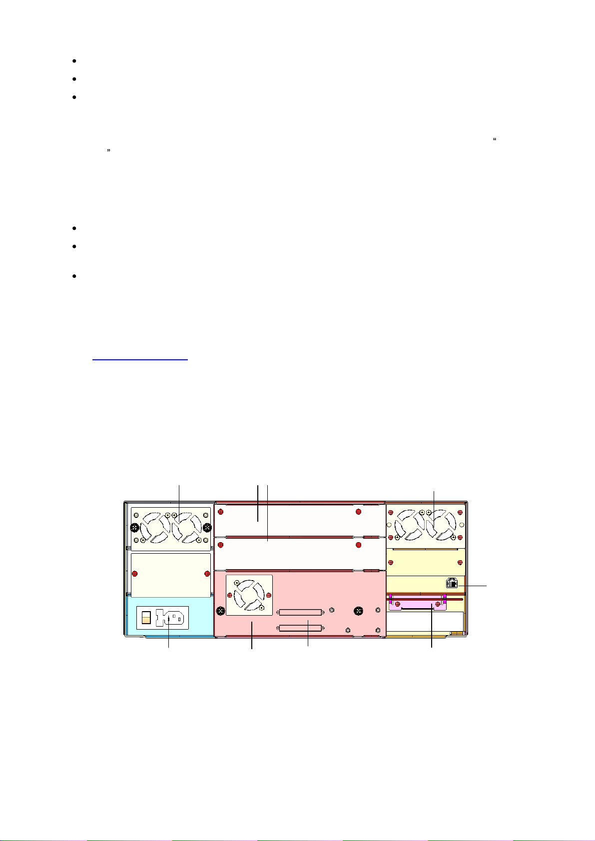
Rear Panel
The figure below shows the rear panel of the
StorageLibrary
.
Figure
2.
Rea
r
Panel of the
StorageLibrary
with 1
Full
-
Height
SCSI
Drive
Installed
Cooling Fans
Forced
-
air cooling fans are integrated in both the power
supply
, the
tape drive,
and behind the
library
control board
. The fans draw air inward throug
h holes in the front bezels and expel it out the back.
The fans start whenever the drive is operating or when the internal temperature in the
StorageLibrary
gets too high.
Main power switch,
power outlet
and fuse
Back panel
cover plate
s
SCSI
connector
s
Emergency eject tool
.
(RTC
battery and
drive
power
extension
cable
behind cover.)
Ethernet
connector
Tape drive
with fan
Power supply
with fans
Cooling fans

6
Product Overview
Main Power Switch/ Fuse/Power
C
ord
C
onnection
The main power switch
is located
at
t
he rear of the library on the power supply bracket. The power
switch, the fuse holder (with a 250V 2A
f
use) and the AC power cord connection are combined in one
common unit.
SCSI and Fiber Channel Interface Connectors
The library supports both SCSI and FC
drives. The SCSI
tape drive
has two shielded 68
-
pin HD SCSI
connectors on the rear panel and the FC
tape drive
has
one
FC connector. The connectors are used
for connecting the tape drive and the
StorageLibrary
to the host. These connectors can link to the
following:
A shielded male HD68 SCSI cable
A shielded male HD68 SCSI terminator
FC port
cable
Ethernet Port
This port is for
networking in support of the Web Client.
It allows
you to connect the StorageLibrary
to
a 10
BaseT
compatible
Ethernet network.
Ba
ttery Holder
The battery for the real time clock is
located
behind a plate at the rear of the library.
A drive power
extension cable is found in the same location.
Back Panel Cover plate
If a drive
bay
is empty
,
a
cover plate
covers the opening to prevent
dust from entering the library.
Library Features
This section describes several features of the
StorageLibrary
.
Operator
Interfaces
The front panel is located on the front of the library and allows
users
to work locally on the library via
the
Operator
inte
rface
(Front Panel Interface, FPI)
. The
Web Client is a
remote management interface
that
allows
users
to view and perform library functions from remote sites and is accessible through a
browser. The front panel
interface and
the Web Client
contain a simila
r
Operator
interface and
functionality. For more information about the front panel and the
Web Client
interface,
see
Information
about
the
Operator
Interfaces
.
ADI Bridging and LUN
The
StorageLibrary
implements
Automation Drive Interface
(
ADI
)
bridging with
Logical Unit
Numbering (LUN
)
addressing. This means that the library controller does not have its own host
interface, but SCSI commands to the library control
ler are sent via one of the installed tape drives.
The tape drive and the library controller will have a common SCSI ID but different LUN numbers. The
SCSI commands to/from the library controller are sent via the tape drives ADI port.
The purpose of the L
UN interface is to eliminate the requirement for a host interface on the library
controller boa
rd
.

StorageLibrary Installation and User Guide
7
Partitions
Partitions are virtual sections within a library that present the appearance of multiple, separate
libraries for purposes of file management, acce
ss by multiple
Operator
s, or dedication to one or more
host applications.
Organizing the library into partitions divides the resources into virtual sections. If one of the resources
is not available due to a failure or other cause, the other partitions and
their assigned components are
still available.
The
StorageLibrary
can be divided into a maximum of four partitions. At least one tape drive and one
magazine must be assigned to each partition. The robot, the import/export
slots
and the cleaning s
lots
are
common resources to all partitions. For more information on partitions
, see
Configuring
Partitions
.
Control Path
The control path tape drive is used to connect a partition to a host applica
tion. Only one tape drive
can be selected as the control path at one time. By default, the first tape drive assigned to a partition
is designated the control path. In the event that the control path connection to the host application
fails, you can select
a new control path for the partition.
I/E Station
I/E station enables importing and exporting cartridges without interrupting normal library operations.
I/E station
slots
are located in
either the lower left or the upper left
magazine. The number of I/E
sl
ots
for the 40
slot
library is
user
settable to 0 (none), 3 or 8. The number of
I/E
slots
for the 24
slot
library
is
user
settable to 0 (none) or 3.
The I/E
slots
are shared among all partitions. When a
cartridge in a
n I/E
slot
is assigned to a partition,
only that partition can access that
I/E
slot
.
Access to the I/E
slot
is managed through the front panel interface only.
Simple Network Management Protocol (SNMP)
The
StorageLibrary
supports system monitoring via SNMP and SNMP Notifications.
Capacity on Dem
and (COD)
In
StorageLibrar
y
, LTO storage
slots
are licensed for use. At any time, Capacity on Demand (COD)
allows you to enable the unused storage
slots
within a library via a
firmware license key. The
StorageLibrary
comes with 24
slots (two lower magazine
s)
and supports licensing of additional 16
slots (two upper magazines)
.
Details about the COD license key
:
The license key does
not expire
.
Once a license key is installed it cannot be removed
.
Contact Technical Support or open a service request to order a
COD License Key. For contact
information,
see
Getting
More
Information
or
Help
.
To see your librarys current configuration and
slot
availability, open
the
home screen
of t
he remote
management interface.
An instruction sheet that describes how to use the license key is provided in the accessory kit.
Once
you receive the license key, enter
it
via the front panel of the library. When the license key is entered,
the total number of avail
able
slots
in the library increases.

8
Product Overview
Browser Requirements
The supported browsers include:
Firefox version 1.0.6
and above
Internet Explorer version 6.0
and above

StorageLibrary Installation and User Guide
9
3 Unpacking the StorageLibrary
This chapter provides detailed information for preparing the library location.
Caution
After the library is unpacke
d it needs to acclimate for 8 hours before the power is
turned on.
Finding a
L
ocation for the
StorageLibrary
The
StorageLibrary
must be positioned in a stable location
.
The
StorageLibrary
is designed to operate in a horizontal position. Do not attempt to
operate the
StorageLibrary
in any ot
her position than horizontally
.
Make sur
e a power source is available
.
Route any cable to avoid walking on them or pinching them with items placed on or against them.
Pay particular attention to the cord at the wall re
ceptacle, and the point where th
e cord exits from
the
StorageLibrary
.
Make sure that object will not fall and liquids will not spill into th
e chassis openings
of the
StorageLibrary
.
Make sure t
he airflow around the front and back of the
StorageLibrary
is n
ot obstructed
.
Make sure t
here is a minimum of 60cm free space in front of the unit to allow the operator
to
safely remove the magazines
.
Make sure t
he display and operator controls can easily be accessed
.
Make sure t
he
StorageLibrary
is away from the floo
r and in a clean environment with
temperatures within specifications. See
Specifications
.
Unpack
Caution
You must remove the
transport locking screws
when powering up the unit for the
first time o
r it will not operate. See the procedure in
section
Remove
the
T
ransport
L
oc
king
Screws
.

10
Unpacking the
StorageLibrary
To unpack the
StorageLibrary
, follow the instructions below.
1.
Carefully unpack the unit
from the shipping container. Save the container and packing materials in
case you need to transport the
StorageLibrary
in the future. The packaging is specifically
designed for the library to ensure it is no
t damaged during transportation.
2.
The
StorageLibra
ry
could be lifted by one person if drives, power supply, and magazines are
removed. However, for absolute safety, it is recommended that two people lift the
StorageLibrary
.
Full library weight = 38 kg / 84 lbs (2 FH drives). Empty library weight = 23.6 kg
/ 52 lbs (does not
include drives, magazines or power supply).
3.
Review the contents of the shipping container to be sure that all parts were included in the
shipment and no parts are damaged. A standard package for the
StorageLibrary
consists of the
follow
ing items:
A factory-
assembled
StorageLibrary
unit conta
ining four cartridge magazines
A
standard accessory kit
containing:
Printed copy of the Quick
Start
Guide
1
Warranty/Registration Information
Rack mounting
kit
including rack mount
ears
2
p
ower
cords
:
one for USA/Japan and one for European power outlets
1 Ethernet cable
Media barcode label kit (contains media labels and cleaning cartridge labels)
There
will be variations of this list.
Depending on the number of drives in your library and whether
or not
your library is equipped with SCSI or FC drives, the accessory kit may contain a terminator
and SCSI cable.
The
StorageLibrary
accessory kit contains no cartridges.
4.
Complete product registration online at
http:/
/www.tandbergdata.com
, Support, Register Your
Product.

StorageLibrary Installation and User Guide
11
4 Installing the Library
This chapter provides detailed information for installing the library hardware. For basic library cabling
instructions, refer to the
Quick
Installation
Guide
.
Remove the
T
ransport
L
oc
king Screws
To protect the library during transport
,
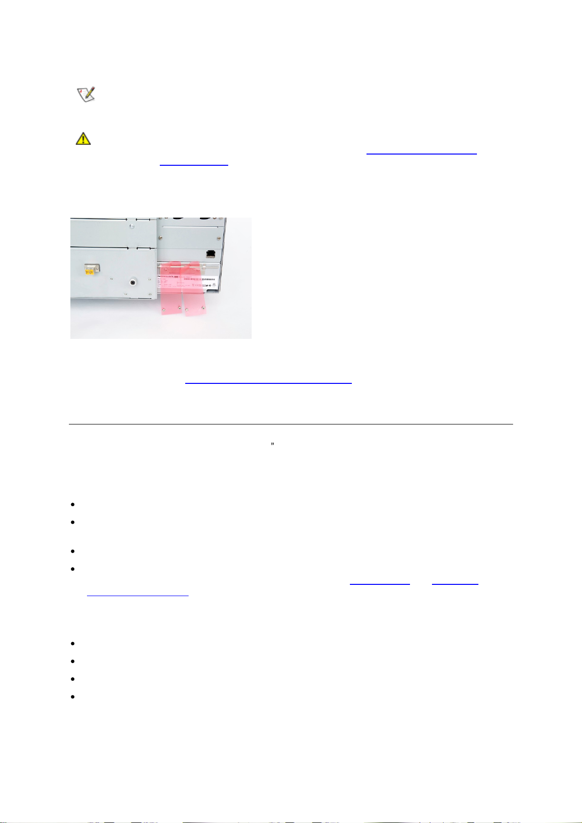
four
transport locking screws
hold the robotics in a locked
position. The screws are marked
with red plastic tabs protruding between the magazines and the front
panel.
Caution
The
transport locking screws
must be removed before the
StorageLibrary
can
operate normally.
Figure
3.
Transport
Lock
ing Screws
Marked with R
ed Plastic Tab
s
The
transport
locking screws will be detected when the
StorageLibrary
is powered on. To remove the
screws
follow the instructions below
:
1
Connect the power cord to the power c
onnector on
the
rear of the library
.
2
Turn on the power sw
itch o
n the rear of the library
.
3
The library detects that the transport
locking
screws are present. Follow the instructions on the
front panel display to remove the magazines to get access to the screws. Remove the sc
rews and
reinsert the magazines
.
12
Installing the Library
The library
will now continue its power
-
on sequence.
Note
Keep the
transport
locking screws i
n a safe place. You will need them
to lock the
robotics
if you need to return your
StorageLibrary
for service or repair.
Caution
The warranty does not cover
damage to t
he library if transported
without the
transport locking screws properly installed. See
Reinserting
the
Transport
Lock
ing
S
crews
for instructions on how to reinstall the
transport lock
ing screws
.
Figure
4.
Recommended
Storage of Transport Locking Screws
If the library is to be mounted in a rack, this is the time you should mount the
rack mount
ears to the
library. See instructions
in
Mounting
the
StorageLibrary
in
a R
ack
.
Mounting the
StorageLibrary
in a
R
ack
The
StorageLibrary
is designed for use in a 19 rack system using 4U of rack space. The length of the
power c
ord and the primary interface cables
restrict the placement.
The
StorageLibrary
is designed to operate in a horizontal position. Do not attempt to operate the
StorageLibrary
in any other position than horizontally. Also make sure that:
The airflow around
the front and back of
the
StorageLibrary
is not obstructed
.
There is a minimum of 60cm free space in front of the unit to allow the operator
to safely remove
the magazines
.
The display and operator
controls can easily be accessed
.
The
StorageLibrary
is awa
y from the floor and in a clean environment with temperatures within
specifications.
For specifications and safety information, see
Specifications
and
Safety
and
Regulatory
Information
.
The
Rack mounting
Kit includes the following items:
Rack mount
Ears (2 ears and 8 screws M
3x4
)
Left Rail
Assembly
Right
Rail
Assembly
Screw M6x12 (6 pieces)
StorageLibrary Installation and User Guide
13
Recommended mounting tools
:
Folding rule or tape measure
Screwdriver
7 mm open
-
end wrench
Figure
5.
Rack mounting
Kit with
Rack mount
Ears (
Right
f
igure)
Mounting the
Rack mount
E
ars
To mount the
rack mount
ears
,
the four magazines must be removed. To r
emove the magazines
,
follow the instructions below:
1
Connect the power cord to the power c
onnector on rear of the library
.
2
Turn on the power sw
itch on the rear of the library
.
3
Wait
until
the library
completes its
power
-
on sequence
.
4
Use the front panel inter
face to remove the magazines (
Menu > Operations
> Eject Magazine
).
5
Physically remove
the magazines from the library
, see
Magazine Handling.
6
If your library supports 24 magazine slots
only
, you
need to use the emergency eject tool to
remove the two upper magazines. The emergency eject tool is located at the rear of the library.
See
Manual/Emergency
Release
of
Magazines
7
Mount the ears to the chassis of the library, see
Figure
6.
Mounting
the
Rack
mount
Ears
.
8
Gently reinsert
the magazines into the library
.
Figure
6.
Mounting
the
Rack mount
Ears
14
Installing the Library
Installing the
Rails
in a Rack
Determine the proper position of the rails in the rack.
Warning
Consider rack stability when deciding where to place the
StorageLibrary
.
Hazardous conditions can result from un
even mechanical loading of a rack.
The
StorageLibrary
uses 4U of vertical rack space. The rails must be installed in a full U position. The
bottom of the rails must be a
ligned with the bottom of a U.
Figure
7.
Rack mount Rail
I
nstalling the Left Rail Assembly
1
Measure the length between the rear
rack mount
rails and the front
rack mount
rails. If the
measurement is shorter than the
StorageLibrary
,
adjust
the two sets of screws M4x12, washers
,
and nuts shown in
Figure
8.
Mounting
the
Rack
mounting
Kit
to
a
Rack
.
2
Adjust the Left Rail Assembly
to fit the measurement in step 1.
3
Use a
7-
mm open
-
end wrench together with the screwdriver to tighten the
two M4x12 screws to
fix the rail length. Using more than two screws increases the stability of the
Rack mounting
Kit.
4
Place the Left Rail Assembly
on the left side of the rack, between the rear
rack mount
rail and the
front
rack mount
rail.
5
Mount the Left
Rail Assembly
at the desired height using one M6x12 screw in front (upper hole in
rail only) and two M6x12 screws at the backside.
Installing the Right Rail Assembly
Follow the instruction for left s
ide, only using the Right Rail Assembly
on the right si
de of the rack.
StorageLibrary Installation and User Guide
15
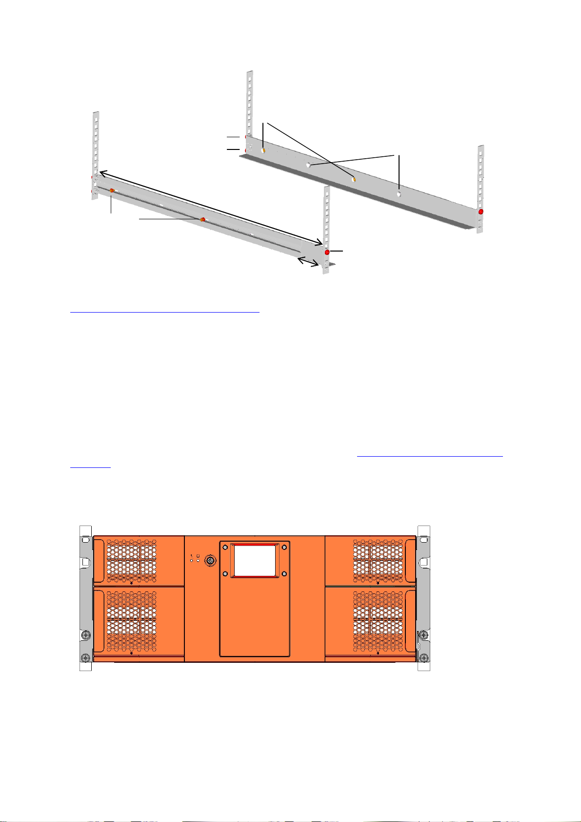
Figure
8.
Mounting
the
Rack mounting
Kit to a Rack
Figure
9.
StorageLibrary
Mounted
in
a
Rack
shows the r
ails
mounted in
a
rack with one screw M6x12
in upper hole on both left and right side. On the rear side, two screws must be used on both left and
right side. A total of six screws are used to install the
rails
to the rack.
Mounting the
StorageLibrary
to the Rack
Make sur
e
that the screws connecting the rails to the rack
are tightened properly before installing the
StorageLibrary
in the rack.
Slide the
StorageLibrary
on the rails from the front of the rack
.
Fix the
StorageLibrary
using
two
M6x12 screw
s
in front of the rac
k
, one
on both left and right side.
T
he lower screw on each side connects the library to the rack, whereas the upper screw on each side
connects the left and right rail assemblies
to the rack
, as shown in
Figure
9.
StorageLibrary
Mounted
in
a
Rack
.
Figure
9.
StorageLibrary
Mounted in a
Rack
, Front View
Rear Rack Mount Rail
Step 5
(Screw M6x12)
Step 3
(Screw M4x12,
nut and washer)
Step 2
Step 5
(Screw M6x12)
Front Rack Mount Rail
Step 1
Holes to be used if rack
depth is shorter than the
StorageLibrary T40
Use these holes if
rack depth is equal
or longer than the
StorageLibrary T40
Step 1

16
Installing the Library
Figure
10
.
StorageLibrary
Mounted in a Rack, Rear View
The f
igure above gives a rear
-
end
view of the
StorageLibrary
mounted in a rack. The
two screws on
each side connect
the
left and right rail assemblies to
the rack.
Installing the
L
ibrary
After mounting, you must
connect the
cable
s
to
the library. Two sets of ca
bling instructions are
available:
For
libraries with SCSI tape drives
For libraries
with Fibre Channel tape drives
For instructions on cabling a library with SCSI tape drives,
see
Connecting
Library
Cables
(SCSI).
For instructions on cabling a library with Fibre Channel tape drives,
see
Connecting
Library
Cables
(Fibre
Channel)
.
If your library
includes both SCSI and Fibre Channel tape drives, cable the tape drive following the
appropriate instructions for that tape drive type
.
Connecting Library Cables (SCSI)
Use this procedure if you are installing a library that includes SCSI tape drives.
F
igure
11
.
StorageLibrary
C
abling (SCSI)

StorageLibrary Installation and User Guide
17
Guidelines for
C
onnecting the SCSI
C
ables
1
Before the SCSI bus cable is connected to the
StorageLibrary
, make sure the
StorageLibrary
power switch is off.
2
Make sure your host system is in a s
tate where a new SCSI device can be safely connected to the
SCSI bus.
3
Do not exceed SCSI bus length restrictions.
a.
Add the length of all external and internal SCSI cables on the bus
.
b.
Add
26.4 cm (10.
4 inch) for the internal cable length in the
StorageLibr
ary
.
c.
The maximum allowed length of an LVD SCSI bus is 12 m (39 ft) if the number of
SCSI devices exceeds two.
4
Before the
StorageLibrary
is powered on and the system is restarted, make sure the SCSI bus is
properly terminated.
Connecting the
C
ables
1.
Instal
l the library in a rack
or
install
the tabletop
kit
.
2.
Connect the SCSI cables to the
tape drive
.
a.
On the bottom tape drive, connect a jumper cable to the top SCSI connector and then to the
bottom SCSI connector on the tape drive above it. Repeat this step fo
r all tape drives on the
SCSI bus. Secure the cable with the t
h
umbscrews on the connectors.
a.
Terminate the last device on the SCSI bus with the appropriate SCSI terminator.
b.
Connect a cable between the last tape drive on the SCSI bus and the host. Note that
there are limitations to the length of the SCSI cable.
3.
Connect your
Ethernet
cable to the
Ethernet
port on the rear of the library
.
This will give
remote
access to the library via the remote management interface. Push the cable
until
it snaps into
place. C
onnect the other end to a normal 10/100 BaseT Ethernet outlet.
4.
Connect a power cord to the outlet on the power supply on the rear of the library.
5.
Power on the library by t
urning on the rear power switch.
6.
Power up the host system.
7.
Verify communication with
all devices on the bus.
8.
Configure your library using the commands on the front panel. For configuration information, refer
to
Configuring
the
Library
.
Warning
Make sure the AC outle
t that you connect the
StorageLibrary power
cable into is
reliably earthed.
Adding the StorageLibrary
to an existing rack installation can cause a leaking
current fault condition because of the summation of the leaking currents.
For security, a 250V 2A fus
e is located near the power switch
.
Note
Tandberg
recommends that all external SCSI devices, including the
StorageLibrary
, are powered on before the computer system is re
-
started (Steps
5 and 6 above).
Connecting Library Cables (Fibre Channel)
Use th
is procedure if you are installing a library that includes Fibre Channel tape drives.

18
Installing the Library
Figure
12
.
StorageLibrary Cabling (Fibre Channel)
1.
Install the library in a rack or
install
the tabletop
kit
.
2.
Connect the fibre cables to the
t
ape drive
.
a.
Attach one end of the fibre cable to the fibre port on each
tape drive
.
a.
Attach the other
end of the cable to the host, switch
or hub
.
Note
The fibre cable can be connected from the tape drive to a switch rather than a
host.
3.
Connect your
Et
hernet
cable to the
Ethernet
port on the rear of the library for remote access to the
library via the remote management interface. Push the cable into it snaps into place. Connect the
other end to a normal 10/100 BaseT Ethernet outlet.
4.
Connect a power cord
to the outlet on the power supply on the rear of the library.
5.
Power on the library by t
urning on the rear power switch.
6.
Power up the host system.
7.
Verify communication with all devices on the bus.
8.
Configure your library using the commands on the front pan
el. For configuration information, refer
to
Configuring
the
Library
.
System Power
-on
At power
-
on, for the first few seconds the unit performs a sequence of diagnostic tests called Power
-
On Self Tests (POST). POST also includes a loop
-
back test of the robot
ics
cabling.
After the POST sequence completes successfully, the library will respond to SCSI selections. Then
the system starts a series of initialization functions, a process that co
nsists of robot calibration
operation and cartridge inventory of magazines and drive.
The
barcode labels on the cartridges will be
read when running inventory.
During these operations
,
the library continuously shows the map status on the screen. The status
of
all magazine
slots
and the drives are initially unknown, and a
question mark (?)
is displayed for each
slot
. As the robot searches the magazine
slots
for cartridges during inventory, the display is updated.
Note
The t
ape drive needs up to 60
seconds
after
power
-
on until
it is
active on the
SCSI bus. You should turn on the power at least
60
seconds before the computer
system is started.

StorageLibrary Installation and User Guide
19
Note
If the self
-
diagnostics and the inventory sequence are successfully completed,
the green LED illuminates an
d the display returns to the home screen. The library
is now ready for further configuration and operation.
If a problem occurs during the power
-
on sequence, the
StorageLibrary
displays an error message on
the display. Refer to
Troubleshooting
to learn the procedures for resolving the problem.
Labeling Cartridges for the Barcode Reader
Y
ou must attach b
arcode labels to the cartridges if you want to use the barcode reader functionality in
the libr
ary.
Caution
You must use
StorageLibrary
-
specific barcode labels to ensure reliable
functionality of the barcode reader.
Cartridge labels must be oriented on the cartridges as shown in the figure below with the locking
mechanism to the left.
Figure
13
.
Positioning of B
arcode
Label for LTO C
artridges


StorageLibrary Installation and User Guide
21
5 Information about the Operator Interfaces
The
StorageLibrary
has two
Operator
interfaces: the Front Panel Interface (FPI) and the Remote
Management
Interface (RMI). Operations on the
StorageLibrary
can be performed locally on the
library using the FPI or remotely on your computer using the remote management interface (RMI).
Similar functionality with common elements is used for both formats.
Note
Both
Front Panel Interface and the R
emote Management Interface are required
to
access all options for operating
the library. Some functionality is only available
through the remote management interface, and some functionality is only
available through the
front panel interface. However, it is recommended that you
use the remote management interface rather than the front panel to perform
library operations whenever possible.
Front Panel Interface (FPI)
The front panel is physically attached to the front of
the library.
The
Operator
interface appears on the
LCD display of the front panel for executing basic library management functions.
The functions of the four control buttons are displayed in the corners of the LCD. The functions of the
buttons change durin
g different activities, and the actual function for each button is always visible on
the display.
The Front Panel includes the
Operator
control panel with LCD display, four control buttons, two LED
indicators and a standby switch.
Scroll Function
The front
panel display is able to
display
20
characters in a line. Some
functionality requires more
than 20
characters.
To access
all
characters a scroll function is implemented.
The buttons on the front
panel are used
to scroll
the text
left or right (a left arro
w appears on the left button and a right arrow
appears on the right button to indicate the scroll function).
T
he number of lines on the display is limited. If the text to be displayed contains more than 8
lines
,
a
similar scroll function as described above
is used.
For line scrolling,
the arrows on the buttons indicate
scroll up or down function.
 Loading...