

Page 1

TANDBERG SLR
Tandberg SLR7, SLR50,
SLR60, SLR75, SLR100, SLR140
SCSI INTERFACE
FUNCTIONAL SPECIFICATION
TANDBERG DATA ASA
P.O. Box 134 Kjelsås
N-0411 OSLO, NORWAY
Phone + 47 22 18 90 90
Telefax + 47 22 18 95 50
© Tandberg Data ASA
Part No. 43 07 43 – 13
October 2003
Page 2

Related publications available from Tandberg Data ASA:
Part No. Title
43 04 44 - 11 Tandberg SLR7, SLR50, SLR60, SLR75, SLR100,
SLR140 Reference Manual
This publication may describe designs for which patents are granted or pending. By publishing this information, Tandberg Data ASA conveys no license
under any patent or any other rights.
Every effort has been made to avoid errors in text and diagrams. However,
Tandberg Data ASA assumes no responsibility for any errors, which may appear in this publication.
It is the policy of Tandberg Data ASA to improve products as new techniques
and components become available. Tandberg Data ASA therefore reserves
the right to change specifications at any time.
We would appreciate any comments on this publication.
Page 3

i Tandberg SLR Product Line SCSI Functional Specifications
Table Of Contents
1. Introduction .....................................................................1
1.1. General .............................................................................................. 1
1.2. Overview............................................................................................ 2
1.3. Glossary............................................................................................. 3
1.4. Additional Reference Documentation................................................ 5
2. About Tape Streamers ....................................................1
2.1. Physical Elements ............................................................................. 1
2.2. Data Storage Characteristics............................................................. 1
2.3. Partitions Within a Volume ................................................................ 3
2.3.1. Partitioning a Volume................................................................. 4
2.3.2. Selecting a Partition ................................................................... 6
2.3.3. Using Initiator Defined Partitions ............................................... 8
2.3.4. Quick File Access .................................................................... 11
2.4. Logical Elements Within a Partition................................................. 14
2.5. Overwrite ......................................................................................... 15
2.6. Using Fixed and Variable Length Blocks......................................... 17
2.6.1. Variable and Fixed Length Blocks ........................................... 17
2.6.2. Writing...................................................................................... 17
2.6.3. Reading.................................................................................... 18
2.6.4. Illegal Length Conditions when Reading ................................. 18
2.7. Data Buffering.................................................................................. 19
2.7.1. Introduction .............................................................................. 19
2.7.2. Data Formatting ....................................................................... 21
2.7.3. Buffered Mode ......................................................................... 23
2.7.4. Read-Ahead............................................................................. 25
2.7.5. Underrun/Overrun .................................................................... 25
2.7.6. Buffer Thresholds..................................................................... 26
2.7.7. Disconnect/Re-connect............................................................ 27
2.7.8. Data Re-transfer ...................................................................... 28
2.7.9. Buffer Parity Errors .................................................................. 28
2.8. Data Compression........................................................................... 29
2.8.1. Background.............................................................................. 29
2.8.2. Controlling Data Compression................................................. 30
2.9. Optimizing Streaming Operation ..................................................... 33
2.9.1. Forced Streaming .................................................................... 33
2.9.2. AVC (Automatic Velocity Control)............................................ 33
2.9.3. Using both Forced Streaming and AVC................................... 34
2.9.4. Recommended Settings .......................................................... 35
2.10. Recorded Objects............................................................................ 35
2.11. TapeAlert ......................................................................................... 36
3. Logical Characteristics...................................................1
3.1. SCSI-bus Phases .............................................................................. 1
3.1.1. Bus Management Phases.......................................................... 1
3.1.2. Information Transfer Phases ..................................................... 2
3.2. SCSI-bus Phase Sequences ............................................................. 3
3.2.1. Legal Phase Sequences............................................................ 4
3.3. SCSI Pointers .................................................................................... 9
3.4. Unit Attention ................................................................................... 11
3.5. SCSI-bus Conditions ....................................................................... 12
3.5.1. Attention (ATN) ........................................................................ 12
3.5.2. Reset........................................................................................ 13
Page 4

Tandberg Data Table of Contents
ii Tandberg SLR Product Line SCSI Functional Specifications
4. Commands.......................................................................1
4.1. The Command Descriptor Block........................................................ 1
4.2. Command Control Byte ..................................................................... 2
4.3. Reserved Fields................................................................................. 3
4.4. Command Set Summary ................................................................... 4
4.5. Command Sequencing...................................................................... 6
4.5.1. Normal Modes............................................................................ 6
4.6. Multiple Connections ......................................................................... 9
4.6.1. Background................................................................................ 9
4.6.2. Commands Received Serially, LUN Is 0.................................. 10
4.6.3. Commands Received Serially, LUN Not 0............................... 11
4.6.4. Concurrent Command, Same Initiator, LUN Is 0 ..................... 11
4.6.5. Concurrent Command, Any Initiator, LUN Not 0 ..................... 11
4.6.6. Concurrent Command, Different Initiator, LUN Is 0................. 11
5. Status Bytes.....................................................................1
6. Message System .............................................................1
6.1. Message In ........................................................................................ 2
6.2. Message Out ..................................................................................... 3
6.3. Extended Message............................................................................ 5
6.3.1. Wide Data Transfer Request ..................................................... 6
6.3.2. Synchronous Data Transfer Request Message......................... 8
6.4. Message Reject Message Handling................................................ 11
6.4.1. Message-In Phase ................................................................... 11
6.4.2. Message-Out Phase ................................................................ 11
6.5. Abort Message Handling ................................................................. 12
6.6. Unexpected Bus Free...................................................................... 14
7. General Exception Handling...........................................1
7.1. Error Codes ....................................................................................... 1
7.2. Error Conditions for All Commands................................................... 5
7.3. Deferred Errors.................................................................................. 6
7.4. Error Conditions for Media Access Commands ................................ 7
7.5. Power On Selftest (POST) Error Handling ........................................ 8
7.5.1. Commands Executed After POST Error .................................... 8
7.5.2. Commands Terminated After POST Error................................. 9
7.6. Bus Parity Error Handling .................................................................. 9
7.6.1. Errors Detected by the Drive ................................................... 10
7.6.2. Errors Detected by the Initiator ................................................ 11
7.7. Buffer Parity Error Handling............................................................. 11
7.8. Error Priority..................................................................................... 12
7.9. Suggested Error Recovery Action ................................................... 13
8. Erase ................................................................................1
8.1. Command Description....................................................................... 1
8.2. Command Descriptor Block............................................................... 1
8.3. Exception Handling............................................................................ 2
8.4. Phase Sequencing ............................................................................ 2
9. Inquiry ..............................................................................1
9.1. Command Description....................................................................... 1
9.2. Command Descriptor Block............................................................... 1
9.3. Parameter Lists ................................................................................. 3
9.3.1. Standard Inquiry Data................................................................ 3
Page 5

Tandberg Data Table of Contents
iii Tandberg SLR Product Line SCSI Functional Specifications
9.3.2. Vital Product Data ...................................................................... 6
9.4. Exception Handling.......................................................................... 16
9.5. Phase Sequencing .......................................................................... 16
10. Load/Unload.....................................................................1
10.1. Command Description ....................................................................... 1
10.2. Command Descriptor Block............................................................... 2
10.3. Exception Handling............................................................................ 3
10.4. Phase Sequencing ............................................................................ 3
11. Locate...............................................................................1
11.1. Command Description ....................................................................... 1
11.2. Command Descriptor Block............................................................... 2
11.3. Exception Handling............................................................................ 3
11.4. Phase Sequencing ............................................................................ 3
12. Log Select ........................................................................1
12.1. Command Description ....................................................................... 1
12.2. Command Descriptor Block............................................................... 1
12.3. Parameter List ................................................................................... 3
12.3.1. General Parameter Description ................................................. 3
12.3.2. Log Page Headers ..................................................................... 3
12.3.3. Log Parameter Headers ............................................................ 3
12.3.4. Modifiable Parameter Values..................................................... 6
12.3.5. The TapeAlert Information Page................................................ 6
12.4. Exception Handling............................................................................ 7
12.5. Phase Sequencing ............................................................................ 7
13. Log Sense ........................................................................1
13.1. Command Description ....................................................................... 1
13.2. Command Descriptor Block............................................................... 1
13.3. Parameter List ................................................................................... 3
13.3.1. Supported Log Pages ................................................................ 3
13.3.2. Buffer Overrun/Underrun Counters Page .................................. 4
13.3.3. Write Error Counter Page .......................................................... 7
13.3.4. Read Error Counter Page ........................................................ 14
13.3.5. TapeAlert Page ........................................................................ 22
13.3.6. Data Block Counters Page ...................................................... 25
13.3.7. Remaining Capacity Page ....................................................... 29
13.3.8. Tape Mark Counters Page....................................................... 36
13.3.9. Head Cleaning Page................................................................ 39
13.3.10. Drive Page ............................................................................... 43
13.3.11. Servo Page ............................................................................. 46
13.3.12. Track Number Page................................................................. 53
13.3.13. Cartridge Usage Page ............................................................. 54
13.3.14. Compression Ratio Page ......................................................... 62
13.4. Exception Handling.......................................................................... 70
13.5. Phase Sequencing .......................................................................... 70
14. Mode Select .....................................................................1
14.1. Command Description ....................................................................... 1
14.2. Command Descriptor Block............................................................... 1
14.3. Parameter List ................................................................................... 2
14.3.1. Header List................................................................................. 3
14.3.2. Block Descriptor List .................................................................. 6
14.3.3. Read-Write Error Recovery Page ............................................ 11
Page 6

Tandberg Data Table of Contents
iv Tandberg SLR Product Line SCSI Functional Specifications
14.3.4. Disconnect/Reconnect Page ................................................... 13
14.3.5. Control Mode Page .................................................................. 16
14.3.6. Data Compression Page.......................................................... 18
14.3.7. Device Configuration Page ...................................................... 20
14.3.8. Medium Partition Page (1) ....................................................... 23
14.3.9. Informational Exceptions Control Page ................................... 27
14.3.10. Miscellaneous Parameters Page ............................................. 29
14.3.11. User Page 0 ............................................................................. 35
14.3.12. User Page 1 ............................................................................. 36
14.3.13. Cartridge Manufacturer Page .................................................. 37
14.4. Exception Handling.......................................................................... 38
14.5. Phase Sequencing .......................................................................... 38
15. Mode Sense .....................................................................1
15.1. Command Description ....................................................................... 1
15.2. Command Descriptor Block............................................................... 2
15.3. Parameter List ................................................................................... 3
15.3.1. Header List................................................................................. 3
15.3.2. Block Descriptor List .................................................................. 5
15.3.3. Read-Write Error Recovery Page Descriptor ............................ 6
15.3.4. Disconnect/Reconnect Page Descriptor .................................... 6
15.3.5. Control Mode Page .................................................................... 7
15.3.6. Data Compression Page Descriptor .......................................... 7
15.3.7. Device Configuration Parameters Page Descriptor................... 8
15.3.8. Medium Partition Parameters Page Descriptor ......................... 8
15.3.9. TapeAlert Configuration Page ................................................... 9
15.3.10. Miscellaneous Parameters Page Descriptor ........................... 10
15.3.11. User Page 0 Page Descriptor .................................................. 10
15.3.12. User Page 1 Page Descriptor .................................................. 11
15.3.13. Cartridge Manufacturer Page .................................................. 12
15.4. Exception Handling.......................................................................... 13
15.5. Phase Sequencing .......................................................................... 13
16. Prevent/Allow Medium Removal ....................................1
16.1. Command Description ....................................................................... 1
16.2. Command Descriptor Block............................................................... 1
16.3. Exception Handling............................................................................ 2
16.4. Phase Sequencing ............................................................................ 2
17. Read .................................................................................1
17.1. Command Description ....................................................................... 1
17.2. Command Descriptor Block............................................................... 2
17.3. Exception Handling............................................................................ 3
17.3.1. General ...................................................................................... 3
17.3.2. No Data...................................................................................... 3
17.3.3. Tapemark Detected ................................................................... 3
17.3.4. Illegal Length.............................................................................. 4
17.3.5. End of Data ................................................................................ 6
17.3.6. End of Partition .......................................................................... 7
17.3.7. Non-Recoverable Read Error .................................................... 7
17.3.8. Illegal Termination...................................................................... 8
17.3.9. Read After Write ........................................................................ 8
17.4. Phase Sequencing ............................................................................ 9
18. Read Block Limits ...........................................................1
18.1. Command Description ....................................................................... 1
Page 7

Tandberg Data Table of Contents
v Tandberg SLR Product Line SCSI Functional Specifications
18.2. Command Descriptor Block............................................................... 1
18.3. Parameter List ................................................................................... 1
18.4. Exception Handling............................................................................ 2
18.5. Phase Sequencing ............................................................................ 2
19. Read Buffer ......................................................................1
19.1. Command Description ....................................................................... 1
19.2. Command Descriptor Block............................................................... 1
19.3. Read Data Mode (2) .......................................................................... 3
19.3.1. Data Buffer (Buffer ID = 0) ......................................................... 3
19.3.2. Static RAM (Buffer ID = 1) ......................................................... 3
19.3.3. Media Statistics (Buffer ID = 2) .................................................. 3
19.3.4. Microcode Store (Buffer ID = 3)................................................. 3
19.3.5. EEPROM (Buffer ID = 4)............................................................ 3
19.3.6. External RAM Adapter (Buffer ID = 5) ....................................... 3
19.3.7. NVP DATA (Buffer ID = 6) ......................................................... 4
19.3.8. Tape Buffer Control Data (Buffer ID = 7) ................................... 4
19.3.9. Volume Directory (Buffer ID = 8)................................................ 4
19.3.10. Dbase Variables (Buffer ID = 9)................................................ 4
19.3.11. Header File Dates (Buffer ID = 10 )................................................. 4
19.3.12. Trace Buffer Control Blocks (Buffer ID = 11) .................................. 4
19.3.13. Complete Trace Buffer (Buffer ID = 12) .......................................... 4
19.4. Read Descriptor Mode (3) ................................................................. 5
19.5. Exception Handling............................................................................ 6
19.6. Phase Sequencing ............................................................................ 7
20. Read Position ..................................................................1
20.1. Command Description ....................................................................... 1
20.2. Command Descriptor Block............................................................... 2
20.3. Data Format....................................................................................... 3
20.4. Exception Handling............................................................................ 4
20.5. Phase Sequencing ............................................................................ 5
21. Receive Diagnostic Results............................................1
21.1. Command Description ....................................................................... 1
21.2. Command Descriptor Block............................................................... 1
21.3. Results From the SEND DIAGNOSTICS Command......................... 3
21.3.1. The Header Page....................................................................... 3
21.3.2. The Diagnostic Pages................................................................ 4
21.3.3. Supported Page Codes ............................................................. 5
21.4. Results From the Stand Alone Diagnostics Test............................... 6
21.4.1. The Stand Alone Diagnostic Result Page.................................. 6
21.5. Exception Handling............................................................................ 7
21.6. Phase Sequencing ............................................................................ 7
22. Release.............................................................................1
22.1. Command Description ....................................................................... 1
22.2. Command Descriptor Block............................................................... 1
22.3. Exception Handling............................................................................ 2
22.4. Phase Sequencing ............................................................................ 2
23. Request Sense.................................................................1
23.1. Command Description ....................................................................... 1
23.2. Command Descriptor Block............................................................... 1
23.3. Parameter List ................................................................................... 2
23.4. Sense Keys........................................................................................ 5
Page 8

Tandberg Data Table of Contents
vi Tandberg SLR Product Line SCSI Functional Specifications
23.5. Additional Sense Code and Qualifier ................................................ 6
23.6. Exception Handling............................................................................ 8
23.7. Phase Sequencing ............................................................................ 8
24. Reserve ............................................................................1
24.1. Command Description ....................................................................... 1
24.2. Command Descriptor Block............................................................... 2
24.3. Exception Handling............................................................................ 2
24.4. Phase Sequencing ............................................................................ 2
25. Rewind..............................................................................1
25.1. Command Description ....................................................................... 1
25.2. Command Descriptor Block............................................................... 1
25.3. Exception Handling............................................................................ 1
25.4. Phase Sequencing ............................................................................ 2
26. Send Diagnostics ............................................................1
26.1. Command Description ....................................................................... 1
26.2. Command Descriptor Block............................................................... 1
26.3. Predefined Selftest Sequence 1........................................................ 3
26.4. Predefined Selftest Sequence 2........................................................ 4
26.5. Exception Handling............................................................................ 5
26.6. Phase Sequencing ............................................................................ 5
27. Space................................................................................1
27.1. Command Description ....................................................................... 1
27.2. Command Descriptor Block............................................................... 2
27.3. Using Fast Space .............................................................................. 3
27.4. Exception Handling............................................................................ 3
27.4.1. General ...................................................................................... 3
27.4.2. No Data...................................................................................... 4
27.4.3. Filemark Detected...................................................................... 4
27.4.4. Setmark Detected ...................................................................... 4
27.4.5. End of Data ............................................................................... 5
27.4.6. Beginning of Partition................................................................ 5
27.4.7. End of Partition ......................................................................... 5
27.4.8. Non-Recoverable Read Error During Space Forward ............... 6
27.4.9. Error Condition or Bad Block During Space Reverse................ 6
28.4.10. Space Forward After Write ........................................................ 7
27.5. Phase Sequencing ............................................................................ 7
28. Test Unit Ready ...............................................................1
28.1. Command Description ....................................................................... 1
28.2. Command Descriptor Block............................................................... 1
28.3. Exception Handling............................................................................ 1
28.4. Phase Sequencing ............................................................................ 2
29. Verify (not for SLR7 and SLR140) ..................................1
29.1. Command Description ....................................................................... 1
29.2. Command Descriptor Block............................................................... 2
29.3. Exception Handling............................................................................ 3
29.4. Phase Sequencing ............................................................................ 3
30. Write .................................................................................1
Page 9

Tandberg Data Table of Contents
vii Tandberg SLR Product Line SCSI Functional Specifications
30.1. Command Description ....................................................................... 1
30.2. Command Descriptor Block............................................................... 2
30.3. Data Compression............................................................................. 2
30.4. Write from BOP.................................................................................. 2
30.5. Write from EOD, Append................................................................... 3
30.6. Writing Over Existing Data, Overwrite............................................... 3
30.7. Terminating Write Operations............................................................ 3
30.8. Exception Handling............................................................................ 4
30.8.1. General ...................................................................................... 4
30.8.2. Unsupported Block Length ........................................................ 4
30.8.3. Illegal Media Type...................................................................... 5
30.8.4 Illegal Overwrite ......................................................................... 6
30.8.5. Illegal Append Tape Format ...................................................... 6
30.8.6. Logical Early Warning................................................................ 6
30.8.7. End of Partition .......................................................................... 7
30.8.8. Non-Recoverable Write Error .................................................... 7
30.8.9. Append Error.............................................................................. 8
30.9. Phase Sequencing ............................................................................ 8
31. Write Buffer......................................................................1
31.1. Command Description ....................................................................... 1
31.2. Command Descriptor Block............................................................... 1
31.3. Write Combined Header and Data Mode (0)..................................... 2
31.4. Write Data Mode (2) .......................................................................... 3
31.5. Download Microcode Mode (4).......................................................... 3
31.6. Download Microcode and Save Mode (5) ......................................... 3
31.7. Download Microcode with Offsets and Save Mode (7) ..................... 4
31.8. Microcode Verification and Save ....................................................... 4
31.9. Microcode Data Format ..................................................................... 5
31.10. Exception Handling............................................................................ 6
31.11. Phase Sequencing ............................................................................ 7
32. Write Filemarks................................................................1
32.1. Command Description ....................................................................... 1
32.2. Command Descriptor Block............................................................... 1
32.3. Terminating Write Operations............................................................ 2
32.4. Write Filemarks from BOM ................................................................ 2
32.5. Exception Handling............................................................................ 2
32.5.1. General ...................................................................................... 2
32.5.2. Illegal Media Type...................................................................... 3
32.5.3. Illegal Append Tape Format ...................................................... 3
32.5.4. Logical Early Warning................................................................ 3
32.5.5. End of Partition .......................................................................... 4
32.5.6. Non-Recoverable Write Error .................................................... 4
32.5.7. Append Error.............................................................................. 5
32.6. Phase Sequencing ............................................................................ 5
Page 10

Tandberg Data Table of Contents
viii Tandberg SLR Product Line SCSI Functional Specifications
Table Of Figures
Figure 2-1: Serpentine Recording ................................................................. 2
Figure 2-2: Logical Track Areas .................................................................... 2
Figure 2-3: Multiple Partition Track Layout (SLR32 example) ....................... 9
Figure 2-4: Overwrite After the 1st Logical Data Block ............................... 16
Figure 2-5: Overwrite of Last Filemark ........................................................ 16
Figure 2-6: The SLR50 Buffer System (Write Mode) .................................. 20
Figure 2-7: The SLR140, SLR100, SLR75, SLR60 and SLR7 Buffer System
(Write Mode) ......................................................................................... 21
Figure 2-8: Host Buffer Data flow During Write Operations ........................ 26
Figure 2-9: Host Buffer Data flow During Read Operations........................ 26
Figure 2-10: Packing Data in Compression Block Groups.......................... 29
Figure 3-1: Phase Sequencing...................................................................... 3
Figure 3-2: SCSI Pointers ........................................................................... 10
Figure 4-1: Connections, Some Examples.................................................. 10
Page 11

Tandberg Data Table of Contents
ix Tandberg SLR Product Line SCSI Functional Specifications
Table Of Tables
Table 1-1: Capacity and medium types.......................................................... 1
Table 2-1: The Medium Partition Page(1) ..................................................... 4
Table 2-2: Minimum Partition Size ................................................................ 8
Table 2-3: Partitions Within A QFA Volume ................................................ 11
Table 2-4: Directory Track set Allocation .................................................... 11
Table 2-5: Data Compression Page Descriptor ........................................... 30
Table 2-6: Forced Streaming and AVC On Different Medium Types (to be
continued…).......................................................................................... 34
Table 3-1: SCSI-bus Phases......................................................................... 1
Table 4-1: Typical Six-byte Command Descriptor Block............................... 1
Table 4-2: Typical Ten-byte Command Descriptor Block .............................. 1
Table 4-3: The Command Control Byte ......................................................... 2
Table 4-4: SCSI Command Set...................................................................... 4
Table 4-5: Normal Mode Actions (to be continued...)..................................... 7
Table 4-6: Connections, LUN and Initiator ID Combinations ...................... 10
Table 5-1: The Status Set ............................................................................. 1
Table 6-1: The Message-In Set..................................................................... 2
Table 6-2: The Message-Out Set .................................................................. 3
Table 6-3: The IDENTIFY Message .............................................................. 4
Table 6-4: Extended Message Format.......................................................... 5
Table 6-5: Supported Extended Message Codes ......................................... 5
Table 6-6: Wide Data Transfer Request ....................................................... 8
Table 6-7: Synchronous Data Transfer Request........................................... 8
Table 6-8: Response to MESSAGE REJECT ............................................. 11
Table 6-9: ABORT TASK SET Message Handling ...................................... 13
Table 7-1: Error Codes (to be continued…) .................................................. 2
Table 7-2: Error Priority ............................................................................... 12
Table 8-1: ERASE Command Descriptor Block ............................................ 1
Table 9-1: INQUIRY Command Descriptor Block ......................................... 1
Table 9-2: INQUIRY Parameter List (to be continued...)............................... 3
Table 9-3: Summary of Supported VPD Pages ............................................ 6
Table 9-4: Unit Serial Number Page ............................................................. 7
Table 9-5: Implemented Operating Definitions Page .................................... 8
Table 9-6: ASCII Implemented Operating Definition Page ........................... 9
Table 9-7: Hardware Revision Levels Page ................................................ 10
Table 9-8: PROM Microcode Revision Level .............................................. 11
Table 9-9: Drive Manufacturing Date Page................................................. 13
Table 9-10: PROM Microcode Creation Date Page .................................... 14
Table 9-11: Drive Adjustment Date Page.................................................... 15
Table 10-1: LOAD/UNLOAD Command Descriptor Block ............................ 2
Table 10-2: LOAD/UNLOAD Operations....................................................... 2
Table 11-1: LOCATE Command Descriptor Block........................................ 2
Table 12-1: LOG SELECT Command Descriptor Block................................ 1
Table 12-2: Parameter Control Byte............................................................... 3
Table 13-1: LOG SENSE Command Descriptor Block ................................. 1
Table 13-2: Supported Log Pages Page....................................................... 3
Table 13-3: Buffer Overrun/Underrun Counters Page .................................. 4
Table 13-4: Underrun Log Parameters ......................................................... 4
Table 13-5: Overrun Log Parameters............................................................. 6
Table 13-6: Write Error Counter Page ........................................................... 7
Table 13-7: Rewrite Counter Log Parameters ............................................... 7
Table 13-8: Total Write Errors Log Parameters ............................................. 9
Table 13-9: Total Write Errors Corrected Log Parameters .......................... 10
Table 13-10: Total Times Errors Processed Log Parameters...................... 11
Table 13-11: Total Bytes Written Parameters .............................................. 12
Table 13-12: Total Uncorrected Write Errors Log Parameters .................... 13
Page 12

Tandberg Data Table of Contents
x Tandberg SLR Product Line SCSI Functional Specifications
Table 13-13: Read Error Counter Page ....................................................... 14
Table 13-14: Reread Counter Log Parameters........................................... 15
Table 13-15: Total Read Error Parameters................................................. 16
Table 13-16: Total Read Error Corrected Log Parameters......................... 17
Table 13-17: ECC Correction Counter Log Parameters ............................. 18
Table 13-18: Total Bytes Read Counter Log Parameters........................... 19
Table 13-19: Total Uncorrected Read Errors Log Parameters .................... 20
Table 13-20: ECC Error Counter Log Parameters ...................................... 21
Table 13-21: TapeAlert Page ....................................................................... 22
Table 13-22: TapeAlert Information Log Parameters................................... 22
Table 13-23: Supported TapeAlert Flags (to be continued…) ..................... 23
Table 13-24: Data Block Counters Page..................................................... 25
Table 13-25: Logical Block Counter Log Parameters ................................. 26
Table 13-26: Write Media Blocks Counter Parameters............................... 27
Table 13-27: Read Media Block Counter Log Parameters ......................... 28
Table 13-28: Remaining Capacity Page ...................................................... 29
Table 13-29: Remaining Capacity Log Parameter code 01 ......................... 30
Table 13-30: Remaining Capacity Log Parameter code 02 ......................... 32
Table 13-31: Maximum Capacity Log Parameter code 03........................... 34
Table 13-32: Maximum Capacity Log Parameter code 04........................... 35
Table 13-33: Tape Mark Counters Page...................................................... 36
Table 13-34: Filemark Counter Log Parameters......................................... 36
Table 13-35: Setmark Counter Log Parameters ......................................... 38
Table 13-36: Head Cleaning Page ............................................................... 39
Table 13-37: Clean Head Log Parameters ................................................. 39
Table 13-38: Head Cleaning Time Log Parameters.................................... 40
Table 13-39: Cleaning Count Log Parameters............................................ 42
Table 13-40: Drive Page ............................................................................. 43
Table 13-41: Total Power On Time Parameters ......................................... 44
Table 13-42: Cartridge Load Counter Parameters...................................... 45
Table 13-43: Servo Page ............................................................................ 46
Table 13-44: Servo Lock Retry Log Parameters........................................ 47
Table 13-45: Servo Track Seek Log Parameters....................................... 48
Table 13-46: Write Servo Lock Lost Counter Log Parameters .................. 49
Table 13-47: Write Servo Dropout Log Parameters.................................... 50
Table 13-48: Read Servo Lock Lost Counter Log Parameters .................. 51
Table 13-49: Read Servo Dropout Log Parameters.................................... 52
Table 13-50: Track Number Page ............................................................... 53
Table 13-51: Cartridge Usage Page............................................................ 54
Table 13-52: Cartridge Serial Number Parameters..................................... 55
Table 13-53: Cartridge Load Counter Parameters...................................... 56
Table 13-54: Cartridge BOT Pass Counter Log Parameters ....................... 58
Table 13-55: Cartridge EOT Pass Counter Log Parameters ....................... 59
Table 13-56: Cartridge Write Pass Counter Log Parameters ...................... 60
Table 13-57: Cartridge Motion Time Log Parameters.................................. 61
Table 13-58: Compression Ratio Page ....................................................... 62
Table 13-59 Write Compression Ratio Log Parameter ................................ 63
Table 13-60: Read Decompression Log Parameter..................................... 64
Table 13-61: Write Compression Interval 1 Log Parameter......................... 65
Table 13-62: Write Compression Interval 2 Log Parameter......................... 66
Table 13-63: Write Compression Interval 3 Log Parameter......................... 67
Table 13-64: Write Compression Interval 4 Log Parameter......................... 68
Table 13-65: Write Compression Interval 5 Log Parameter......................... 69
Table 14-1: MODE SELECT Command Descriptor Block ............................ 1
Table 14-2: MODE SELECT Header List...................................................... 3
Table 14-3: Available Tape Speeds for SLR140............................................ 3
Table 14-4: Available Tape Speeds for SLR100............................................ 4
Table 14-5: Available Tape Speeds for SLR75.............................................. 4
Table 14-6: Available Tape Speeds for SLR60.............................................. 4
Page 13

Tandberg Data Table of Contents
xi Tandberg SLR Product Line SCSI Functional Specifications
Table 14-7: Available Tape Speeds for SLR50............................................. 5
Table 14-8: Available Tape Speeds for SLR7................................................ 5
Table 14-9: MODE SELECT Block Descriptor List ....................................... 6
Table 14-10: Density codes, formats and suitable medium .......................... 6
Table 14-11: Type of Media Related to Tape Format ................................... 8
Table 14-12: Fixed Block Lengths................................................................. 9
Table 14-13: Legal Block Lengths (bytes)................................................... 10
Table 14-14: Read-Write Error Recovery Page Descriptor......................... 11
Table 14-15: Disconnect/Reconnect Page Descriptor ................................ 13
Table 14-16: Control Mode Page Descriptor............................................... 16
Table 14-17: Data Compression Page Descriptor ...................................... 18
Table 14-18: Device Configuration Page Descriptor................................... 20
Table 14-19: Medium Partitions Page......................................................... 23
Table 14-20: Maximum Additional Partitions................................................ 24
Table 14-21: Using the FDP, SDP and IDP bits.......................................... 25
Table 14-22: Informational Exceptions Control Page.................................. 27
Table 14-23: Miscellaneous Page Descriptor ............................................. 29
Table 14-24: BSYI Usage............................................................................. 31
Table 14-25: BSYA Usage ........................................................................... 31
Table 14-26: User Page 0 Page Descriptor ................................................ 35
Table 14-27: User Page 1 Page Descriptor ................................................ 36
Table 14-28: Cartridge Manufacturer Data Parameters.............................. 37
Table 15-1: MODE SENSE Command Descriptor Block .............................. 2
Table 15-2: MODE SENSE Header List........................................................ 3
Table 15-3: MODE SENSE Block Descriptor List ......................................... 5
Table 16-1: PREVENT/ALLOW MEDIUM REMOVAL Cdb ........................... 1
Table 17-1: READ Command Descriptor Block ............................................ 2
Table 17-2: Illegal Length Summary .............................................................. 6
Table 18-1: READ BLOCK LIMITS Command Descriptor Block .................. 1
Table 18-2: READ BLOCK LIMITS Data....................................................... 1
Table 19-1: READ BUFFER Command Descriptor Block............................. 1
Table 19-2: Read Buffer Modes ..................................................................... 2
Table 19-3: Read Buffer ID’s.......................................................................... 2
Table 19-4: READ BUFFER Descriptor List.................................................. 5
Table 19-5: Buffer Capacity............................................................................ 6
Table 20-1: READ POSITION Command Descriptor Block.......................... 2
Table 20-2: READ POSITION Data .............................................................. 3
Table 21-1: RECEIVE DIAGNOSTIC RESULTS Command Block................ 1
Table 21-2: The Header Page........................................................................ 3
Table 21-3: The Diagnostic Pages ................................................................. 4
Table 21-4: Supported Page Codes.............................................................. 5
Table 21-5: The Stand Alone Diagnostic Page ............................................. 6
Table 22-1: RELEASE Command Descriptor Block..................................... 1
Table 23-1: REQUEST SENSE Command Descriptor Block ....................... 1
Table 23-2: REQUEST SENSE Parameter List ............................................ 2
Table 23-3: Sense Key Specific Information, Invalid Fields ........................... 3
Table 23-4: Sense Keys ................................................................................. 5
Table 23-5: Additional Sense Code and Qualifier (to be continued…) ......... 6
Table 24-1: RESERVE Command Descriptor Block..................................... 2
Table 25-1: REWIND Command Descriptor Block........................................ 1
Table 26-1: SEND DIAGNOSTIC Command Descriptor Block..................... 1
Table 26-2: SEND DIAGNOSTICS Functions............................................... 2
Table 27-1: SPACE Command Descriptor Block .......................................... 2
Table 28-1: TEST UNIT READY Command Descriptor Block ...................... 1
Table 28-2: TEST UNIT READY Response................................................... 1
Table 29-1: VERIFY Command Descriptor Block ........................................ 2
Table 30-1: WRITE Command Descriptor Block........................................... 2
Table 30-2: Legal Media/Drive Combinations ............................................... 5
Table 31-1: WRITE BUFFER Command Descriptor Block ........................... 1
Page 14

Tandberg Data Table of Contents
xii Tandberg SLR Product Line SCSI Functional Specifications
Table 31-2: Supported Modes....................................................................... 2
Table 31-3: Microcode Data Format.............................................................. 5
Table 32-1: WRITE FILEMARKS Command Descriptor Block ..................... 1
Page 15

1-1 Tandberg SLR Product Line SCSI Functional Specifications
1.
Introduction
1.1. General
This manual covers the SCSI Specifications for the
Tandberg SLR Product Line Tape Drives. Currently there
are six available models:
Tandberg SLR140
Tandberg SLR100
Tandberg SLR75
Tandberg SLR60
Tandberg SLR50
Tandberg SLR7
This manual replaces Part no. 430743–12, titled,
“ Tandberg SLR7, SLR50, SLR60, SLR75, SLR100. SCSI
Interface Functional Specification.”
The main differences between the five models are
capacity, data transfer rate and the medium types
supported. The following table shows the different
capacities and read/write compatibility for the various
drive models.
Medium Type1Capacity
2
SLR7 SLR50 SLR60 SLR75 SLR100 SLR140
SLRtape140 70/140 Gbyte N/A N/A N/A N/A N/A Read/Write
SLRtape100 50/100 Gbyte N/A N/A N/A N/A Read/Write Read/Write
SLRtape75 38/75 Gbyte N/A N/A Read/Write Read/Write Read/Write Read/Write
SLRtape60 30/60 Gbyte N/A N/A Read/Write Read/Write Read/Write Read/Write
SLRtape50 25/50 Gbyte N/A Read/Write Read/Write Read/Write Read/Write Read/Write
SLRtape40 20/40 Gbyte N/A N/A Read/Write Read/Write Read/Write Read/Write
SLRtape7 20/40 Gbyte Read/Write N/A Read Read Read Read
SLR32 16/32 Gbyte N/A Read/Write Read Read Read N/A
SLRtape24 12/24 Gbyte N/A Read/Write Read Read Read N/A
SLR5 4/8 Gbyte Read Read Read Read N/A N/A
DC9250 2.5/5 Gbyte N/A Read Read
3
Read N/A N/A
Table 1-1: Capacity and medium types
If a certain functional specification is valid for a
particular drive, two methods are used to separate the
different specifications throughout this manual:
1)
The specific functional specification is marked out
with horizontal lines, or
2)
Footnotes are used to indicate for which drive the
specification applies.
The specifications described in this publication are
subject to change without notice.
1
All drives supports different variants of these medium types. See
table 30-3 for details.
2
The highest number is with 2:1 data compression.
The actual capacity on brand new or old and worn tapes may be lower.
3
On SLR60 tape drives with MAN. DATE 2802 (July 2002) or higher.
Page 16

Tandberg Data Introduction
1-2 Tandberg SLR Product Line SCSI Functional Specifications
1.2. Overview
Chapter 2
Describes tape streamers in general and the Tandberg SLR
Product Line Tape Drives in particular. The chapter also
describes volume partitioning, the overwrite function,
the usage of fixed and variable length data blocks, the
data buffer system and data compression.
Chapter 3
Gives a description of the SCSI logical characteristics
as implemented by the Tandberg SLR Product Line Tape
Drives.
Chapter 4
Specifies the SCSI Command Descriptor Blocks (CDB) in
general.
Chapter 5
Lists the Status Bytes implemented by the Tandberg SLR
Product Line Tape Drives.
Chapter 6
Describes the SCSI Message system as implemented by the
Tandberg SLR Product Line Tape Drives.
Chapter 7
Specifies the Tandberg SLR Product Line Tape Drives
exception handling in general.
Chapters 8 - 32
Detailed specifications of the SCSI commands.
Page 17

Tandberg Data Introduction
1-3 Tandberg SLR Product Line SCSI Functional Specifications
1.3. Glossary
BOM Beginning Of Medium. The extreme position along the medium
in the direction from the supply-reel, which can be
accessed by the use of a REWIND command.
BOP
Beginning Of Partition. The position at the beginning of the
permissible recording region of a partition. If only one
partition is defined, this position is equivalent to BOM
(see above).
BOT
Beginning Of Tape. Physical marker on the tape marking the
start of the useful area of the tape (located at BOM,
see above).
CDB Command Descriptor Block. The structure used to communicate
commands from an Initiator to a Target.
Compression Block
Group
A group of compressed data recorded as one variable
length block. The Compression Block Group either
contains a number of host-defined logical fixed length
blocks, or a complete or partial host-defined variable
length logical block. The Compression Block Group also
contains a Compression Header as its initial sequence of
data.
Compression
Header
A sequence of uncompressed data at the beginning of each
Compression Block Group. The Compression Header contains
specific information related to this Compression Block
Group.
Disconnect
The action that occurs when a SCSI device releases
control of the SCSI-bus, allowing it to go to the BUS
FREE phase.
EOD End Of Data. A tape format specific end-of-data indication
on the current partition. The recording medium may be
positioned at EOD by reading until the Drive signals an
EOD exception or by issuing a SPACE command with a Space
Code of 3 (Space to End-Of-Data).
EOM
End Of Medium. The extreme position along the medium in
the direction from the take-up-reel, which can be
accessed by the device. This position may be accessed by
the use of a LOAD/UNLOAD command with the EOT-bit set to
one.
EOP End Of Partition. The position at the end of the permissible
recording area of a partition. If only one partition is
defined, this position is equivalent to EOM (see above).
EOT
End Of Tape. Physical marker on the tape marking the end
of the useful area of the tape (located at EOM, see
above).
EW
Early Warning. Physical tape-mark near - but logically
before - EOP (independent of physical direction).
Field
A group of one or more contiguous bits. Fields
containing only one bit are usually referred to as the
XX bit instead of the XX field.
Initiator
SCSI-bus Device issuing SCSI commands to a SCSI Target.
LED
Light Emitting Diode. An indicator on the front of the
Drive.
LEW Logical Early Warning. Simulated EW marker on the last track
on each partition. LEW is moved some distance in front
of the actual EW.
LSB
Least Significant Bit.
LUN
Logical Unit Number.
MLR
Multi Channel Linear Recording.
MSB
Most Significant Bit.
Page 18

Tandberg Data Introduction
1-4 Tandberg SLR Product Line SCSI Functional Specifications
Overlength
The incorrect length condition that exists after
executing a read group command, when the length of the
actual block read exceeds the requested transfer length
in the command descriptor block (CDB).
Page
Several commands use regular parameter structures that
are referred to as pages. These pages are identified
with a value known as a page code.
Parameter
A structure containing one or more fields.
Partition
The entire region of recording and reading paths in a
volume or in a portion of a volume.
Reconnect
The act of re-establishing the physical Initiator/Target
connection. A Target reconnects to an Initiator by
issuing RESELECTION and MESSAGE IN phases after winning
arbitration.
Reserved
The term used for bits, fields and code values that are
set aside for future standardization.
SCSI
Small Computer Systems Interface. Industry standard computer
peripheral interface. Used to connect several devices
via a common data and control bus.
SCSI address
The representation of the unique address (0-7) assigned
to a SCSI device. This address would normally be
assigned and set in the SCSI device during system
initialization.
SCSI ID
The bit-significant representation of the SCSI address
referring to one of the SCSI-bus data lines.
Signal assertion
The act of driving a signal to the true state.
Signal de-assertion
The act of driving a signal to the false state.
SLR
Scaleable Linear Recording.
Status
One byte of information sent from a Target to an
Initiator upon completion of each command.
Third-party
When used in reference to RESERVE or RELEASE commands,
third-party means a reservation made on behalf of
another device.
Target
SCSI-bus Device receiving/executing SCSI commands.
TLA Three Letter Acronym.
Track Set
A logical collection of N physical tracks which are
written or read simultaneously. A track set can be
viewed as a logical track that holds N times as much
data as a physical track and can transfer data N times
as fast as a physical track. A track set may consist of
only a single track, i.e. N = 1.
Underlength
The incorrect length condition that exists after
executing a read group command when the requested
transfer length in the command descriptor block (CDB)
exceeds the length of the actual block read.
Volume
A recording medium together with its physical carrier.
Page 19

Tandberg Data Introduction
1-5 Tandberg SLR Product Line SCSI Functional Specifications
1.4. Additional Reference Documentation
[1] Tandberg Data ASA, “ Tandberg SLR Product Line
Reference Manual” , Revision 6, Publ. No. 90316, December 1999.
[2] American National Standards Institute, “ SCSI-2,
Enhanced Small Computer System Interface” , ANSI
Standard X3.131-1994.
[3] American National Standards Institute, “ SCSI-3,
Primary Commands” , ANSI Working Draft
X3T10/995D, Revision 11a, 28 March 1997.
[4] American National Standards Institute, “ SCSI-3
Stream Device Command Set” , ANSI Working Draft
X3T10/997D, Revision 22, 1-Jan-2000.
[5] American National Standards Institute, “ SCSI-3
Interlocked Protocol” , ANSI Working Draft
X3T10/856D, Revision 10, 31 Mar 1996.
[6] American National Standards Institute, “ SCSI-3
Parallel Interface” , ANSI Working Draft
X3T10/855D, Revision 15a.
American National Standards Institute, “ SCSI-3
Parallel Interface 2” , ANSI Working Draft
X3T10/855D, Revision 20b.
[7] QIC, “ Development Standard For 1/4-inch
Cartridge Tape Drive SCSI-2 Interface” , QIC121, Revision P, 14-Dec-1995.
[8] QIC, “ Adaptive Lossless Data Compression” ,
QIC-154, Revision A, 10-Mar-1994.
[9] QIC, “ Serial Recorded Magnetic Tape Cartridge
For Information Interchange” , QIC-2GB-DC,
Revision B, 10-Mar-1994.
[10] QIC, “ Serial Recorded Magnetic Tape Cartridge
For Information Interchange” , QIC-4GB-DC,
Revision B, 20-Apr-1997.
[11] Tandberg Data ASA, “ Serial Recorded Magnetic
Tape Cartridge For Information Interchange” ,
SLR6 Tape Format, Revision A, 1998.
[12] QIC, “ Serial Recorded Magnetic Tape Cartridge
For Information Interchange” , QIC-5010-DC,
Revision E, 15-Dec-1994.
[13] Tandberg Data ASA, “ Serial Recorded Magnetic
Tape Cartridge For Information Interchange” ,
MLR3 Tape Format, Revision A, 30-Aug-1995.
[14] Tandberg Data ASA, “ Advanced Linear Recording
Format 1” , ALRF-1, Revision B, 22-Apr-1998.
[15] QIC, “ Serial Recorded Magnetic Tape Cartridge
For Information Interchange” , QIC-CRF1,
Revision J, 15 Jun 1995.
[16] Tandberg Data ASA, “ Advanced Linear Recording
Format 2” , ALRF-2, Revision 1. 24-Apr-2000.
[17] Tandberg Data ASA, “ Advanced Linear Recording
Format 6” , ALRF-6, Revision 2.00-Oct-2002
[18] American National Standards Institute, “ SCSI-3
Fast-20” , ANSI Working Draft X3T10/1071D,
Revision 6.
Page 20

Tandberg Data Introduction
1-6 Tandberg SLR Product Line SCSI Functional Specifications
This Page Intentionally Left Blank
Page 21

2-1 Tandberg SLR Product Line SCSI Functional Specifications
2.
About Tape Streamers
2.1. Physical Elements
Tape streamer devices optimize their use in storing or
retrieving user data in a sequential manner. Since
access is sequential, position changes typically take
long time, when compared to direct-access devices like
disks.
The recording medium used with the Drive consists of a
flexible substrate coated with a magnetic material. The
recording medium is wound onto two reels.
Both the supply reel and the take-up reel are
encapsulated into a cartridge. Several standards exist,
covering the construction of cartridges for interchange.
A complete unit composed of the recording medium and its
physical carrier (the cartridge) is called a volume. In
tape streamers like the Tandberg SLR Product Line Tape
Drives, the volumes are removable.
When a volume is inserted it has the attribute of being
loaded or unloaded. Loaded is the state when the
streamer device is capable of executing commands that
cause the medium to be moved (so-called media access
commands). A volume is unloaded when the media access
commands can not be executed (that is when these
commands report CHECK CONDITION status and a NOT READY
sense key).
Not Write-Protected
Write-Protected
The write-protected state determines
whether an Initiator may or may not
write information on a volume. This
attribute is controlled by the user of
the volume through the SAFE-switch on
the cartridges.
The recording medium has two physical
attributes called Beginning-Of-Tap
e
(BOT) and End-Of-Tape (EOT). BOT is at
the end of the medium that is attached
to the take-up reel. EOT is at the end
of the medium that is attached to the
supply reel.
2.2. Data Storage Characteristics
Serpentine
Recording Method
The position on the medium where a pattern of recorded
signal may be written by one write component is called a
track or track set which may consist of either one, two
or four tracks, depending on the tape format used. On a
new volume, recording of a track set begins after
mounting the volume and then by moving the tape from BOT
toward EOT. When EOT is approached, the direction of
recording is reversed and the Drive starts recording a
track set from EOT towards BOT. This process repeats the
number of times necessary to record all track sets. The
total number of track sets depends on the tape format
used. This method of recording is called serpentine.
Page 22

Tandberg Data About Tape Streamers
2-2 Tandberg SLR Product Line SCSI Functional Specifications
BO T EO T
BO P
EO P
Figure 2-1: Serpentine Recording
A track set is read in the same sequence as when
writing.
When reading data using a DC9250, SLR5 or SLRtape7
medium, the drive is aided by reference tracks to
position the read/write head accurately.
For the DC9250 and SLR5 media the drive
1
, writing these
tapes from BOT, has to provide the tape with the
required reference bursts during write. The writing and
reading of reference bursts are done automatically by
the drive and are completely transparent to the user.
The reference bursts are pre-recorded on SLRtape7 media.
The reading of reference bursts are done automatically
by the drive and are completely transparent to the user.
On the other hand, SLRtape140, SLRtape100, SLRtape75,
SLRtape60, SLRtape50, SLRtape40, SLR32 and SLRtape24
media have pre-recorded servo tracks, and the reading
and writing of reference bursts are therefore not
required. The servo tracks are used to position the
read/write head both during the read and write
operations. The reader should be aware of this
distinction when meeting the term “ reference bursts”
later in this manual. See [9] – [17] for further
information on reference bursts and servo tracks.
From the Initiators point of view the recording medium
may be looked upon as having a single large continuous
logical track starting with an area called Beginning-Of-
Media (BOM) and ending with an area called End-Of-Media
(EOM). BOM is always on the same side of the volume as
BOT. EOM may be located at the BOT or at the EOT
depending on whether the total number of track sets is
odd or even.
The logical track is split into several areas separated
by markers. At least four parts may be identified:
Beginning-Of-Media End- Of-MediaEarly-Warning AreaRecording Area
BO T L P LEW EW EO T
Figure 2-2: Logical Track Areas
1
Drives covered by this manual can only read DC9250 and SLR5 media.
Page 23

Tandberg Data About Tape Streamers
2-3 Tandberg SLR Product Line SCSI Functional Specifications
Beginning-Of-Media
This area holds no user data. It is used to record a
special reference burst as defined in [9], [10]. This
area starts with the BOT (Beginning Of Tape) tape marker
and ends at the LP (Load Point) tape marker.
Recording Area
This area holds the user data. This area starts with the
LP (Load Point) tape marker and ends at the LEW (Logical
Early Warning) marker.
Early-Warning Area
When writing, the Initiator needs an indication that it
is approaching the end of the Recording-Area. This
position called Logical Early Warning (LEW) is reported
to the Initiator at a position early enough for the
Drive to write out any buffered data to the medium while
still leaving enough room for additional recorded data
or tapemarks. The actual amount of data is user
configurable, see the LEW Position field in Section
14.3.9. This area ends at the EW (Early Warning) tape
marker.
End-Of-Media
This is the short area between the EW (Early Warning)
and the EOT (End-Of-Tape) tape markers. It is usually
possible to complete the writing of a single last frame
between EW and EOT. When this has been done or when EOT
is found, all further write operations are discontinued
even if the there are more data to be written in the
data buffer.
2.3. Partitions Within a Volume
A volume may be split into several mini-volumes called
partitions. Each partition has its own set of beginning
and ending points. Each partition within a volume has
defined its own Beginning-Of-Partition (BOP), RecordingArea, Early-Warning-Area and End-Of-Partition (EOP).
In the first partition (partition zero) on a volume with
n partitions, BOP is identical to BOM. In the last
partition on a volume (partition n-1), EOP is identical
to EOM.
All volumes have a minimum of one partition called
partition zero, or the default partition.
When a volume is mounted (that is inserted into the
Drive and then loaded), the volume is logically
positioned to the beginning of the default partition
(partition zero). This is also true when a LOAD command
(with the Load bit set to one) is executed. When a
REWIND or ERASE command is received in any partition,
the Drive positions to the beginning of the current
partition.
Page 24

Tandberg Data About Tape Streamers
2-4 Tandberg SLR Product Line SCSI Functional Specifications
2.3.1. Partitioning a Volume
Setting up a Medium Partition page and then executing a
MODE SELECT command transferring this page to the Drive
can partition a volume. The table below shows the parts
of the Medium Partition Page(1) that relate to this
procedure. Fields of no interest are marked with
“ XX...XX” .
BYTE BIT 7 6 5 4 3 2 1 0
00
PS
XX Page Code = 11h
01 Parameter Length = 4Eh
02
Maximum Additional Partitions
03
Additional Partitions Defined
04
FDP SDP IDP PSUM
XX XX XX
05 XXXX
06 XXXX
Partition Units
07 XXXX
08
Partition Size Descriptor 0
09
| . . .
|
78
Partition Size Descriptor 35
79
Table 2-1: The Medium Partition Page(1)
Note that the Tandberg SLR Product Line Tape Drives use
the long form of the Medium Partition Page(1). This
means that the Partition Size Descriptor fields are
always present (both in MODE SELECT and MODE SENSE
parameter data).
Note also that the Medium Partition Page(1) is not
savable (the MODE SENSE command returns a Medium
Partition Page(1) where the PS bit is set to zero).
Partitioning a volume is only allowed when the volume is
positioned at BOM (the beginning of partition 0). Note
also that a partition operation may lead to a loss of
all existing data (the Drive runs an erase pass in each
of the existing partitions if the new partitioning is
different from the existing partitioning found on the
medium).
The Tandberg SLR Product Line Tape Drives allow the
Initiator to specify partitioning using two different
methods. The first is the most general. The Initiator
can specify both the number of partitions and their
individual sizes. Using the second method the Initiator
may only specify whether one or two partitions are
requested. When a single partition is requested it will
cover the whole medium. When two partitions are requested the Drive will allocate them fixed sizes (there
will be one large and one small partition).
The Initiator Defined Partitions (IDP) bit is used to
select between the two methods. When the IDP bit is one,
the first method is used (the number and size of
partitions may be specified).
Page 25

Tandberg Data About Tape Streamers
2-5 Tandberg SLR Product Line SCSI Functional Specifications
When the IDP bit is zero, the second method is used. In
this case the FDP bit is used to select one or two fixed
size partitions. This method of using partitions is
often called “ Quick File Access” (QFA).
Regardless of which method is used, executing a MODE
SELECT command where the Medium Partition Page(1) is
included in the parameter list, some form of
partitioning will take place. This means that such a
MODE SELECT command is only accepted at the beginning of
partition 0 (BOP0).
The Partition Size Unit of Measure (PSUM) field defines
the unit of the Partition Size Descriptors. A value of
2 specifies the unit to be MBytes and a value of 3
specifies the unit to be GBytes. MODE SELECT will
ignore this field when the IDP bit is not set. MODE
SENSE will return 2 (MBytes) in this field when the
currently mounted volume has a capacity (uncompressed)
of 65535 MBytes or less. MODE SENSE will return 3
(GBbytes) in this field when the capacity is above 65535
MBytes. This boundary is introduced because 65535
(FFFFh) is the maximum value of the Partition Size
Descriptors.
The Partition Units field defines the unit of the
Partition Size Descriptors when the PSUM field is set to
3. The Partition Units must be set to 9 when the PSUM
field is set to 3 to indicate that GBytes (10
9
) is the
only supported unit.
The Maximum Additional Partitions field is ignored by
the MODE SELECT command. When the Medium Partition
Page(1) is returned by the MODE SENSE command this field
is used to indicate the maximum number of partitions (in
addition to the default partition) that the current
medium is able to hold.
The Additional Partitions Defined field is used to
specify the requested number of partitions (MODE SELECT)
or it shows the actual number of partitions (MODE
SENSE). The Partitions Size Descriptors is used to
specify the requested size of each partition (MODE
SELECT) or to show the current (estimated) size of each
partition (MODE SENSE).
Note that setting the IDP or FDP bits to one is only
allowed when the medium to be partitioned is a
SLRtape140 to SLRtape7 or SLR32, medium. In this case a
maximum of 24 partitions is allowed when using a
SLRtape140, SLRtape100, SLRtape75, SLRtape60 or
SLRtape40 medium. A maximum of 36 partitions is allowed
when using a SLRtape50, SLR32 or SLRtape24 medium. A
maximum of 3 partitions is allowed when using a SLRtape7
medium. (See also section 2.3.3 Using Initiator Defined
Partitions).
When using other medium types, partitioning can not be
used and only a single partition is available.
When partition sizes are quoted later on in this
section, all sizes are uncompressed sizes.
Page 26

Tandberg Data About Tape Streamers
2-6 Tandberg SLR Product Line SCSI Functional Specifications
2.3.2. Selecting a Partition
Two commands makes it possible to select a partition for
read or write operations; the LOCATE command and the
MODE SELECT command.
2.3.2.1. Selecting a Partition Using LOCATE
The LOCATE command can be used to specify the active
partition. The Change Partition (CP) must be set to one
and the Partition field must be set to the desired
partition. The addressed partition must exist on the
volume mounted. The Drive will then move to the
specified partition before the actual block locate
operation starts.
The READ POSITION and MODE SENSE commands may be used to
read the current partition number in use.
When the partition has been changed, the Drive will stay
in the selected partition for all media access commands
until one of the following actions are taken (by the
Initiator):
A new LOCATE with CP set to one is executed.
A MODE SELECT command is executed that changes the
state of the Active Partition field in the Device
Configuration Parameters Page (page code 10h).
A LOAD command is executed. This command always
brings the tape to the beginning of the default
partition (partition 0).
The cartridge is removed from the Drive. A newly
inserted cartridge must be loaded before it can be
accessed. The load operation positions the tape at
the beginning of the default partition (partition 0).
This will be true whether the load operation happens
as a result of an Auto Load or an explicit LOAD
command (with the Load bit set to one).
2.3.2.2. Selecting a Partition Using MODE SELECT
The MODE SELECT command can be used to specify the
active partition. The Device Configuration Parameters
Page (page code 10h) is used for this purpose. The
Change Active Partition (CAP) bit must be set to one and
the Active Partition field must be set to the desired
partition. The addressed partition must exist on the
volume mounted. The Drive will then position the tape at
the beginning of the specified partition.
The READ POSITION and MODE SENSE commands may be used to
read the current partition number in use.
When the partition has been changed, the Drive will stay
in the selected partition for all media access commands
until one of the following actions are taken (by the
Initiator):
A new MODE SELECT command is executed that changes
the state of the Active Partition field.
Page 27

Tandberg Data About Tape Streamers
2-7 Tandberg SLR Product Line SCSI Functional Specifications
A LOCATE with CP set to one is executed.
Page 28

Tandberg Data About Tape Streamers
2-8 Tandberg SLR Product Line SCSI Functional Specifications
A LOAD command is executed. This command always
brings the tape to the beginning of the default
partition (partition 0).
The cartridge is removed from the Drive. A newly
inserted cartridge must be loaded before it can be
accessed. The load operation positions the tape at
the beginning of the default partition (partition 0).
This will be true whether the load operation happens
as a result of an Auto Load or an explicit LOAD
command (with the Load bit set to one).
2.3.3. Using Initiator Defined Partitions
When using a SLRtape140 to SLRtape7 or SLR32, medium the
Initiator may specify both the number and the size of
partitions (the IDP bit is set to one).
The following table shows the minimum number of tracks
and track sets that can be allocated to a partition for
each medium type. It also shows the maximum number of
partitions and the minimum partition size.
Medium Type
Min. Track Sets
Min. Tracks
Max. Partitions
Min. Partition Size
SLRtape140 2 8 24 2916 MBytes
SLRtape100
2
8
24
2083 MBytes
SLRtape75 2 8 24 1563 MBytes
SLRtape60 2 8 24 1250 Mbytes
SLRtape50 2 4 36 694 Mbytes
SLRtape40 2 8 24 833 MBytes
SLRtape7 12 24 3 6666 Mbytes
SLR32 2 4 36 444 Mbytes
SLRtape24 2 4 36 333 Mbytes
Table 2-2: Minimum Partition Size
All partitions start at the BOT side of the medium. This
means that the Drive will be able to access any
partition with a minimum of tape movements after an
auto-load or a LOAD command.
Page 29
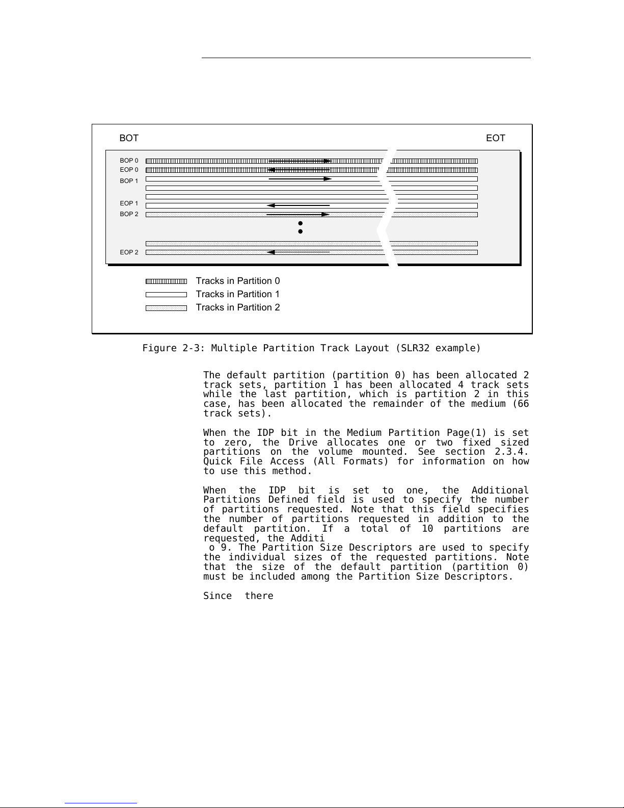
Tandberg Data About Tape Streamers
2-9 Tandberg SLR Product Line SCSI Functional Specifications
Here is a simple example using an SLR32 medium. The
volume has been partitioned into 3 partitions (one
default partition and 2 additional partitions):
BOT EOT
BOP 0
EOP 0
EOP 2
BOP 2
BOP 1
EOP 1
Tracks in Partition 0
Tracks in Partition 1
Tracks in Partition 2
Figure 2-3: Multiple Partition Track Layout (SLR32 example)
The default partition (partition 0) has been allocated 2
track sets, partition 1 has been allocated 4 track sets
while the last partition, which is partition 2 in this
case, has been allocated the remainder of the medium (66
track sets).
When the IDP bit in the Medium Partition Page(1) is set
to zero, the Drive allocates one or two fixed sized
partitions on the volume mounted. See section 2.3.4.
Quick File Access (All Formats) for information on how
to use this method.
When the IDP bit is set to one, the Additional
Partitions Defined field is used to specify the number
of partitions requested. Note that this field specifies
the number of partitions requested in addition to the
default partition. If a total of 10 partitions are
requested, the Additional Partitions Defined must be set
to 9. The Partition Size Descriptors are used to specify
the individual sizes of the requested partitions. Note
that the size of the default partition (partition 0)
must be included among the Partition Size Descriptors.
Since there is no provision in a Partition Size
Descriptor to identify the number of a partition, the
number of a partition is the relative position of the
Partition Size Descriptor in the Medium Partition
Page(1). The size of partition 0 is specified in the
first Partition Size Descriptor, that is in bytes 8 and
9. Partition 1 is specified in bytes 10 and 11, etc.
Page 30

Tandberg Data About Tape Streamers
2-10 Tandberg SLR Product Line SCSI Functional Specifications
When the Medium Partition Page(1) is used to specify the
size of any partition, the Partition Size Descriptor
fields are used to specify a requested size. As the
actual partition size must match an integral number of
track set pairs, the Drive will round the value
requested up to the nearest number divisible by the
minimum partition size given by the loaded medium (see
table 2-2). As an example, if a partition is requested
to have a value of 450 MBytes, the Drive will round the
size up to 666 MBytes (333 * 2) when using an SLRtape24
medium, up to 694 MBytes when using an SLRtape50 medium
and up to 2916 MBytes when using an SLRtape140 medium.
If a partition is requested to have a size of 200
MBytes, the Drive will round the size up to 333, 444,
694 or 2916 Mbytes and so on. The Partition Size
Descriptors returned by the MODE SENSE command may be
used to read out the partition sizes after rounding has
taken place.
The number of Partition Size Descriptors must always
equal the Maximum Addition Partition plus one,
specifying the size of the default partition plus all
additional partitions. When the Additional Partitions
Defined is less than the Maximum Additional Partitions,
the last Partition Size Descriptors are set to zero. If
the Maximum Additional Partitions field has a value of
35 and the Additional Partitions Defined has a value of
n, then there must be n+1 non-zero Partition Size
Descriptors. These descriptors must be the first n+1
descriptors (the medium has been partitioned into n+1
partitions numbered 0 through n). The last 35-n Partition Size Descriptors are all set to zero. The size of
partition 0 (the default partition) must be greater than
zero.
The sum of all sizes requested by the non-zero Partition
Size Descriptors may be less than the total size on the
medium. In this case some capacity remains inaccessible.
Sometimes it may be desirable to have the last partition
cover the remainder of the medium. In this case the last
non-zero Partition Size Descriptor can be set to a value
of FFFFh.
If insufficient space exists on the medium for the
requested partition sizes or if multiple Partition Size
Descriptors are set to FFFFh, the Drive will return
CHECK CONDITION status.
When medium information has been read by the Drive, the
Medium Partition Page(1) returned by a MODE SENSE
command indicates the actual partitioning on the
currently mounted volume (the number and size of each
partition). When medium information has not yet been
read by the Drive, the Additional Partitions Defined and
the Partition Size Descriptor fields are undefined and
set to zeros. The SLR5 and DC9250 media have limited
medium information and the Additional Partitions Defined
and the Partition Size Descriptor fields are always
undefined and set to zeros for these media.
Note however that the partitions sizes returned by a
MODE SENSE command are estimated sizes. The sizes are
based on the calculated capacity for a given number of
pairs of track sets. The actual size achieved may differ
from the estimated size due to such factors as tape
length variations, the number of re-writes and amount of
filler data written by the Drive.
Page 31

Tandberg Data About Tape Streamers
2-11 Tandberg SLR Product Line SCSI Functional Specifications
2.3.4. Quick File Access
Partitions can be used to support the implementation of
QFA (Quick File Access). QFA is a feature which provides
support for two partitions on a volume, a directory
partition and a data partition. When using QFA the
initiator is not allowed to specify the size of those
partitions. Only the number of partitions (one or two)
can be specified.
The QFA mode can be enabled and disabled with the FDP
bit of the Medium Partition Page(1). When not in QFA
mode the Drive will implement a single partition
covering the whole tape. This single partition is called
the Default Data Partition.
Note that QFA is only supported when the medium to be
partitioned is a SLRtape140 to SLRtape7 or SLR32 medium.
Partition
Use
0 Data
1 Directory Information
Table 2-3: Partitions Within A QFA Volume
In QIC compatible tape streamers like the Tandberg SLR
Product Line Tape Drives, all partitions start on track
set boundaries at the physical BOT end of the tape. Two
track sets (a total of 4 tracks) are allocated to the
directory partition when using the SLR6, QIC-5010-DC,
MLR3 or ALRF-2 tape formats. For the ALRF-1 and ALRF-6
tape format two track sets (a total of 8 tracks) are
allocated. All remaining track sets are allocated to the
data partition.
The following table shows the directory track set
allocation for all supported tape formats:
Medium Type
Approximate Size Directory Track (Set) Number
SLRtape140 2916 MBytes 46 and 47
SLRtape100 2083 MBytes 46 and 47
SLRtape75 1563 MBytes 46 and 47
SLRtape60 1250 MBytes 46 and 47
SLRtape50 694 MBytes 70 and 71
SLRtape40 833 MBytes 46 and 47
SLRtape7 1111 MBytes 34 and 35
SLR32 444 MBytes 70 and 71
SLRtape24 333 MBytes 70 and 71
Table 2-4: Directory Track set Allocation
When the medium has been identified the Medium Partition
Page(1) returned by a MODE SENSE command may indicate
the actual partitioning on the currently mounted volume
(the number and size of each partition). When the medium
has not been identified the Additional Partitions
Defined and the Partition Size Descriptor fields are
undefined.
Note that the partition size(s) returned by a MODE SENSE
command are estimated sizes. The sizes are based on the
calculated capacity for a given number of tracks. The
actual size achieved may differ from the estimated size
due to such factors as tape length variations, the
Page 32

Tandberg Data About Tape Streamers
2-12 Tandberg SLR Product Line SCSI Functional Specifications
number of re-writes and amount of filler data written by
the Drive.
Page 33

Tandberg Data About Tape Streamers
2-13 Tandberg SLR Product Line SCSI Functional Specifications
2.3.4.1. Setting QFA-Mode
The MODE SELECT command is used to enter or leave the
QFA mode.
The Drive will be in non-QFA mode when the FDP bit in
the Medium Partition Parameter Page (Page Code 11h) is
set to zero. The Drive will be in QFA mode when the FDP
bit is set to one.
When going into QFA mode the FDP bit must be set to one
(the IDP bit must be set to zero). The Page Length field
must be set to 4Eh (to keep the page at a non-changing
length). The Maximum Additional Partitions field is
ignored. The Additional Partitions Defined field is
ignored (the Drive always partition the volume into two
partitions when FDP set to one). The SDP and the IDP
bits must be set to zero. The PSUM and Partition Units
fields are ignored. The CLEAR and ADDP bits must be set
to zero. The Medium Format Recognition field must be set
to 01h (the value returned by the MODE SENSE command).
The Partition Units field must be set to zero. The
Partition Size Descriptor fields are ignored by the
drive (they can have any value).
When leaving QFA mode (when partitioning the volume into
a single partition) all fields have the values given
above. The only exception is that the FDP bit is set to
zero.
Setting or clearing the FDP bit is only legal when the
tape is positioned at BOT. Note also that a change in
partitioning (going from 1 to 2 partitions or the other
way around) leads to loss of all existing data (the
Drive runs an erase pass in each of the existing
partitions).
Since the Medium Partition Page(1) is not savable, the
Initiator is responsible for making sure that the
correct QFA mode is active whenever a new cartridge is
loaded.
When a QFA mode corresponding to the currently loaded
volume is in effect, the Medium Partition Page(1)
returned by the MODE SENSE command will indicate both
the number of partitions in effect and the size of those
partitions. In non-QFA mode the Additional Partitions
Defined field returns 00h (indicating a single
partition). The very first Partition Size Descriptor
field returns the approximate size of the default (and
only) partition. In QFA mode the Additional Partitions
Defined field returns 01h (indicating a total of two
partitions). The first Partition Size Descriptor field
returns the approximate size of the data partition while
the second Partition Size Descriptor field indicates the
approximate size of the directory partition.
2.3.4.2. Changing Partition Using The LOCATE Command
The LOCATE command can be used to specify the active
partition. The Change Partition (CP) must be set to one
and the Partition field must be set to 0 (Data
Partition) or 1 (Directory Partition). The Drive will
then move to the specified partition before the actual
block locate operation starts.
Page 34

Tandberg Data About Tape Streamers
2-14 Tandberg SLR Product Line SCSI Functional Specifications
2.3.4.3. Changing Partition Using the MODE SELECT
Command
The MODE SELECT command can be used to specify the
active partition. The Device Configuration Parameters
Page (page code 10h) is used for this purpose. The
Change Active Partition (CAP) bit must be set to one and
the Active Partition field must be set to 0 (Data
Partition) or 1 (Directory Partition). The Drive will
then position the tape at the beginning of the specified
partition.
2.4. Logical Elements Within a Partition
The Recording-Area on a volume may contain two types of
Initiator accessible elements; data blocks and tape
marks. These elements are controlled and transferred
between the Initiator and the medium using READ, WRITE
and WRITE FILEMARKS commands.
A unit of data supplied or requested by the Initiator is
called a logical block. Logical blocks are stored
according to the specifications of the tape format used
(see [9] - [14]) and may be recorded as one or more
physical blocks on the medium. When the physical block
and the logical block are not recorded in a one-to-one
relationship, it is the responsibility of the device to
perform all blocking, de-blocking or padding of the
logical block(s) sent to/from the Initiator.
Filemarks are one kind of tape marks. Filemarks are
special recorded elements containing no user data.
Initiators traditionally use filemarks to separate user
data from labels and logical groupings of data from each
other.
Setmarks are another kind of tape marks. Setmarks are
special recorded elements containing no user data,
providing a segmentation scheme hierarchically superior
to filemarks.
Interblock gaps, the gaps between blocks and tapemarks,
are introduced on the medium at the time a block or
tapemark is written without explicit action by the
Initiator. Minimum and maximum lengths for interblock
gaps are defined in [9] - [14].
In addition to blocks, tape marks and inter-block gaps,
erase gaps can be recorded. An erase gap is
automatically recorded when a write operation is
properly terminated. The erase gap acts as an end-ofdata marker on some tape formats.
In addition a single erase gap may be recorded on the
medium through the use of the ERASE command. This erase
gap will cover the whole - or a limited part - of the
medium and the pre-recorded information in the erase gap
will be written over and lost. Refer to section 8 for
further details about the ERASE command.
Page 35

Tandberg Data About Tape Streamers
2-15 Tandberg SLR Product Line SCSI Functional Specifications
After writing data from BOP on a partition, the medium
is considered to be a contiguous grouping of blocks,
filemarks, setmarks and gaps. Certain ANSI standards
define gap lengths which, if exceeded, are to be considered as having reached blank medium. Depending on the
tape format, this blank medium may be treated as an endof-data indication or an unrecoverable medium error
causing an interchange error. Unrecorded volumes (new or
erased) may exhibit blank medium characteristics if an
attempt is made to read or space the volume before data
have been written.
2.5. Overwrite
Normally tape streamers do not allow update of data
already written on a volume. The structure and layout of
the physical elements on the Recording-Area are such
that they do not facilitate writing over old data with
new data in the middle of a partition. When writing new
data on a volume there are only two possibilities:
A write operation may be started from BOP. All
existing data on that partition will be destroyed.
This is true even if the new write operation writes
less data than the amount of data already on the
partition. The data “ left” on the partition can not
be recovered.
A write operation may append data to existing data on
a partition. In this case the medium must be
positioned at end-of-data (EOD) before the write
operation is started. The medium may be positioned at
EOD by reading or spacing until the Drive indicates
EOD. It is also possible to position the medium to
EOD by executing a SPACE command with a Space Code of
3 (Space to EOD).
If the current tape position is not at BOP or EOD, a
write operation will be terminated immediately with
CHECK CONDITION status and the Error Code is set to W
RITE
A
PPEND ERROR
(Write After Read).
However, in addition to the two possibilities mentioned
above, the Tandberg SLR Product Line Tape Drives offer
under certain conditions the following two overwrite
capabilities:
The data following the very first data block in a
partition may be written over (leaving the first data
block intact). The following restrictions do however
apply:
1)
The medium must be positioned after the 1st
logical block in partition 0.
2)
The length of this block must be less than 65536
(10000h) bytes when using a SLRtape140 to SLRtape7
or SLR32, medium or less than 32768 (8000h) bytes
when using an SLR5 or DC9250 medium.
3)
There must be no tapemarks either immediately in
front of or immediately after the 1st data block.
Page 36

Tandberg Data About Tape Streamers
2-16 Tandberg SLR Product Line SCSI Functional Specifications
BO P EO P
1s t block
1s t block
Other existing data
New data written over ex ist ing data
Bef ore
After
Figure 2-4: Overwrite After the 1st Logical Data Block
The last filemark in a partition may be written over.
The following restrictions do however apply:
1)
The filemark must be the last of two sequential
filemarks.
2)
EOD must follow immediately after the filemark to
be written over (no data must follow the two
filemarks).
3)
The medium must be positioned in front of the
filemark to be written over.
BO P EO P
2nd fmk
New data written over last fmk
Before
After
EO D
!st fmk
!st fmk
EO D
Figure 2-5: Overwrite of Last Filemark
The overwrite capability is a configurable feature. It
is controlled by the EOWR bit in the Miscellaneous
Parameters Page of the MODE SELECT command.
Page 37

Tandberg Data About Tape Streamers
2-17 Tandberg SLR Product Line SCSI Functional Specifications
2.6. Using Fixed and Variable Length Blocks
2.6.1. Variable and Fixed Length Blocks
The Drive is capable of supporting both fixed and
variable length logical blocks. The concept of fixed or
variable mode for writing and reading blocks only
indicates the method by which the Initiator specifies
the size of the logical block for transfer and not the
method of recording physical blocks on the medium.
When writing the Drive transforms logical blocks passed
from the Initiator into physical blocks to be stored on
the tape. The length of a logical block may vary while
the length of a physical block is defined by the tape
format in use (see [9] - [14]). When reading the Drive
transforms physical blocks from the tape back into
logical blocks to be transferred to the Initiator,
When executing read and write commands two parameters
must be specified; the block length and the number of
blocks to read or write. As the SCSI read and write
commands only have room for a single parameter, only the
block length or the number of blocks can be specified
directly. For this reason there are two different
versions of each command capable of transferring tape
data to or from the Initiator. The fixed length type
commands can specify the number of blocks to be
processed. For these commands all blocks will be of
equal size. The actual size is given by the current
value in the Block Size field in the Block Descriptor
List of the MODE SELECT command. The variable length
type commands can specify the length of the individual
blocks, but the number of blocks written is always only
one (for each command).
When the Block Size field has a value different from
zero, the Drive is said to be in fixed block mode. In
this mode both the fixed length type commands and the
variable length type commands are allowed. When the
Block Size field is zero, the Drive is said to be in
variable block mode. In this mode only the variable
length type commands are allowed (as writing fixed
length blocks of size zero bytes does not make any
sense).
Note that the illegal length handling in the READ
command differs slightly depending on the current
fixed/variable mode set by the MODE SELECT command.
2.6.2. Writing
When writing, the Drive groups the data transferred from
the Initiator into blocks. Data blocks may be written
with two different versions of the WRITE command; one
with the fixed (FIX) bit set and one with the fixed
(FIX) bit cleared.
When the FIX bit is cleared, a WRITE command will write
a single block. The block length may be specified on a
block-by-block basis. This is useful when writing blocks
of varying length.
Page 38

Tandberg Data About Tape Streamers
2-18 Tandberg SLR Product Line SCSI Functional Specifications
When the FIX bit is set to one, a WRITE command may
write multiple blocks. The WRITE command must specify
the number of blocks to write. All written blocks will
be of the same length. The block size is controlled by
the Block Size field in the MODE SELECT Block Descriptor
List. Depending on the tape format used, different fixed
block sizes are supported.
Note that when the Block Size field has been set to
zero, the Drive is said to be in Variable Block mode and
commands with the FIX bit set to one are not allowed.
2.6.3. Reading
When reading data off a tape, the Drive is able to
determine the length of each block read. When reading,
the expected block length must be specified. This can be
done in two different ways with the two different
versions of the READ command; one with the fixed (FIX)
bit set and one with the fixed (FIX) bit clear.
When the FIX bit is clear, a READ command will read a
single block. The expected block length may be specified
on a block-by-block basis.
When the FIX bit is set to one, a READ command may read
multiple blocks. The READ command must specify the
number of blocks to read. The expected block length of
all blocks is the same. The expected length is specified
with the MODE SELECT command (the Block Size field of
the Block Descriptor List). Note that when the Block
Size field has been set to zero, the Drive is said to be
in Variable Block mode and commands with the FIX bit set
to one are not allowed.
2.6.4. Illegal Length Conditions when Reading
When the specified block length does not match the
actual block length, the READ command will complain (if
the Suppress Illegal Length Indicator (SILI) bit was not
set in the READ Command Descriptor Block).
If the actual block length is smaller then the expected
block length, the READ command will transfer the actual
number of bytes found in the block. The READ command is
then terminated with a CHECK CONDITION Status. The
Illegal Length Indicator will be set in the Sense Data
List. If the fixed-bit is cleared, the Information Bytes
will be set to the difference between the expected
number of bytes and the actual number of bytes. This
will be a positive number in this case. If the fixed-bit
is set, the Information Bytes will be set to the
difference between the specified number of blocks and
the actual number of blocks transferred. The block with
the unexpected length is counted among the transferred
blocks even if its length was wrong. Note that this
means that the Information Bytes may read zero even if
the READ command was terminated with CHECK CONDITION and
Illegal Length Indication. The logical tape position
will be at the beginning of the next block on the tape.
Page 39

Tandberg Data About Tape Streamers
2-19 Tandberg SLR Product Line SCSI Functional Specifications
If the actual block length is larger than the expected
block length, the READ command will transfer the
expected number of bytes only. The READ command is then
terminated with a CHECK CONDITION Status. The Illegal
Length Indicator will be set in the Sense Data List. If
the fixed-bit is cleared, the Information bytes will be
set up with the difference between the expected number
of bytes and the actual number of bytes. This will be a
negative number in this case. The information bytes are
presented as a 32 bit 2's complement number. If the
fixed-bit is set, the Information bytes will be set up
with the difference between the specified number of
blocks and the actual number of blocks transferred. The
block with the unexpected length is counted among the
transferred blocks even if its length was wrong. Note
that this means that the Information Bytes may read zero
even if the READ command was terminated with CHECK
CONDITION and Illegal Length Indication. The logical
tape position will be at the beginning of the block
following the block with the unexpected length. This
means that the additional bytes in the block with the
unexpected length are lost.
2.7. Data Buffering
2.7.1. Introduction
The Drive has a temporary storage area capable of
holding one or more blocks or tapemarks – a data buffer.
The data buffer may hold any combination of data blocks
and tapemarks in the process of being written to the
recording medium, or it may contain read-ahead data
blocks and tapemarks transferred from the recording
medium.
The data buffer operates as a FIFO queue, compensating
for the different transfer rates on the SCSI-bus and the
tape system. The Drive is usually only connected to the
SCSI-bus for short amounts of time when bursts of data
are transferred at a much higher speed than the normal
tape transfer rate. The data buffer can be in one out of
two modes; read mode or write mode. The data buffer is
in write mode when executing WRITE or WRITE FILEMARKS
commands. The data buffer is in read mode when executing
LOCATE, READ, SPACE or VERIFY
1
commands.
1
VERIFY is not supported by SLR7 and SLR140
Page 40

Tandberg Data About Tape Streamers
2-20 Tandberg SLR Product Line SCSI Functional Specifications
2.7.1.1. SLR50 Drive
The data buffer in the SLR50 Drive has been split into
two distinct partitions, a host buffer and a tape
buffer.
Host Buffer
The host buffer is used to buffer logical blocks
transferred at high-speed (up to 20 MBytes/s) to/from
the SCSI interface. Notice that only data are buffered
in the host buffers. Tapemarks do not occupy any space
in the host buffer. Tapemarks do however consume other
resources in the buffers system so there is an upper
limit to the number of tapemarks that the buffer system
is able to hold.
Tape Buffer
The tape buffer is used to buffer formatted physical
blocks going to/from the recording medium. The data in
the tape buffer is transferred to/from the media at
speeds varying from up to 2 MBytes/s (SLRtape50 medium)
down to 480 KBytes/s (DC9250 medium).
A data formatting unit sits in the data path between the
host buffer and the tape buffer. An optional data
compression unit may also be placed in the data path
between the two buffers.
Lo g i cal Block
Lo g i cal Block
Lo g i cal Block
Lo g i cal Block
Lo g i cal Block
Physica l Fr am e
Physica l Fr am e
Physica l Fr am e
SC SI Bus
Medium
Host Buffer Tape Buffer
Data
Fo r matter
Data
Com pression
Figure 2-6: The SLR50 Buffer System (Write Mode)
In a SLR50 Drive equipped with a 1 MByte physical data
buffer the host buffer will occupy about 450 KBytes
while the tape buffer is allocated 512 KBytes. For
drives equipped with a 2 MByte physical data buffer the
host buffer will occupy about 1450 KBytes while the tape
buffer is allocated 512 KBytes.
Note that the use of the host buffer is optimized so
that as long as most logical blocks are of the same size
the complete allocated size for the host buffer is
utilized to buffer data. When mixing blocks of different
sizes or when a very large number of tapemarks are
flowing through the buffer system, the effective host
buffer size may be somewhat less than the allocated
size.
Page 41

Tandberg Data About Tape Streamers
2-21 Tandberg SLR Product Line SCSI Functional Specifications
2.7.1.2. SLR7, SLR60, SLR75, SLR100 and SLR140 Drives
The data buffer in the SLR7, SLR60, SLR75, SLR100 and
SLR140 Drives consists of a single logical unit with a
size of nearly 8 MByte.
Data Buffer
The data buffer is used to buffer data from logical
blocks transferred at high-speed (up to 40 MBytes/s)
to/from the SCSI interface. When moved into the buffer
the data is first compressed and then formatted into
frames of physical blocks. The data in the data buffer
is then transferred to/from the media at speeds varying
from up to 6 MBytes/s (SLR140) down to 3 Mbytes/s
(SLR7).
Lo g ica l Block
Lo g ica l Block
Physica l Fr am e
Physica l Fr am e
Physica l Fr am e
SC SI Bus Medium
Data Buffer
Data
For matter
Data
Com pression
Lo g i cal to Physica l M apping
Figure 2-7: The SLR140, SLR100, SLR75, SLR60 and SLR7 Buffer System (Write
Mode)
Note that the use of the buffer is optimized so that as
long as most logical blocks are of the same size the
complete allocated size for the host buffer is utilized
to buffer data. When mixing blocks of different sizes or
when a very large number of tapemarks are flowing
through the buffer system, the effective buffer size may
be somewhat less than the physical size.
2.7.2. Data Formatting
When data are moved from the host buffer to the tape
buffer it is grouped into physical blocks. The physical
blocks are again grouped into frames. In addition to
host related data and tapemarks the frames hold additional information like error correction codes (ECC) [9]
- [17].
The size of the physical block as well as the number of
blocks per frame depend on the tape format used [9] –
[17].
The tape buffer is used to buffer complete frames. The
maximum number of frames depends on the tape format in
use. With an SLR32 medium for example, the tape buffer
is able to hold up to 16 frames each holding a maximum
Page 42

Tandberg Data About Tape Streamers
2-22 Tandberg SLR Product Line SCSI Functional Specifications
of 52 physical blocks of user data (each block is 512
bytes long). In addition each frame has 12 blocks of ECC
information [13]. For other tape formats the values
differs.
Page 43

Tandberg Data About Tape Streamers
2-23 Tandberg SLR Product Line SCSI Functional Specifications
The size of a logical data block may be different than
the size of a physical data block. In the tape buffer
the size of a physical block is fixed (as given by the
current tape format). In the host buffer the size of a
logical block may vary since the Drive supports a wide
range of fixed- and variable logical block sizes. The
required blocking and de-blocking into logical blocks is
handled by the data-formatting unit.
When the data compression option is not used, one
logical block usually occupies at least one complete
physical block. There is one exception. When writing 512
byte blocks with the FIXED bit set to one, a special option is used on SLR5 and DC9250 media allowing two
logical blocks to share one physical block [9] - [10].
Large logical blocks may span several physical blocks.
When data compression is used, the number of physical
blocks needed for each logical block depends on the
compression ratio achieved.
2.7.3. Buffered Mode
The Drive is capable of operating in both a buffered
mode and an unbuffered mode. Buffered mode is not
applicable during read commands. When operating in
buffered mode the Drive returns GOOD status for write
operations when all data have been successfully
transferred from the Initiator into the data buffer.
When operating in unbuffered mode, GOOD status is not
returned until all requested data or tapemarks are
successfully recorded on the medium.
When issuing a buffered WRITE FILEMARKS command with the
immediate bit set to one, GOOD status is returned as
soon as the tapemark(s) has been moved into the data
buffer. A WRITE FILEMARKS command with the immediate bit
set to zero causes any buffered data blocks or tapemarks
to be written to the medium. Upon successful completion
of this process, which is called a synchronize
operation, no data blocks or tapemarks remain in the
data buffer. (Host may perform this synchronize
operation without writing actual tapemarks by specifying
zero in the number of tapemark field in the WRITE
FILEMARK command).
Should an unrecoverable write error occur while in
buffered mode, the Drive generates an error condition.
The error is reported on the next applicable operation
as a deferred error.
Note that when operating in buffered mode the Drive will
pack physical blocks from one WRITE or WRITE FILEMARKS
command together with physical blocks from the previous
WRITE or WRITE FILEMARKS command into the same frame
(when a frame based tape format is used). This is not
true when operating in non-buffered mode. If a WRITE or
WRITE FILEMARKS command does not transfer enough data
(or tapemarks) to fill a complete frame, the rest of the
frame is filled up with filler blocks. This may of
course waste a lot of space on a tape. When reading a
tape containing frames with filler blocks the Drive is
able to remove the filler blocks without generating any
discontinuities in the data stream on the SCSI-bus.
Note, however, that even if filler blocks are inserted
Page 44

Tandberg Data About Tape Streamers
2-24 Tandberg SLR Product Line SCSI Functional Specifications
and removed automatically by the Drive they will occupy
buffer space both in read mode and write mode.
Page 45

Tandberg Data About Tape Streamers
2-25 Tandberg SLR Product Line SCSI Functional Specifications
2.7.4. Read-Ahead
When operating in read mode the Drive always tries to
fill up the buffer with read-ahead data. This means that
when a read type command terminates the Drive continues
to read data off the tape. The read-ahead only stops
when the data buffer is full, if a non-read command is
issued or if there is no more data to read. The readahead also stops when an uncorrectable block has been
detected.
Read-ahead minimizes tape start and stops because when a
read type command (including SPACE and VERIFY
1
) follows
another read type command the wanted data may already be
ready in the data buffer.
When an error has been detected by the tape system the
Drive does not report the error until all data up to the
point where the error occurred has been read out of the
data buffer. This means that if an unrecovered read
error has occurred this error is not reported until an
Initiator requests the data block in error.
2.7.5. Underrun/Overrun
When the Drive is in write mode data is moved from the
data buffer on to the tape. The tape write operation can
only continue as long as there is any data left to write
in the data buffer. If the buffer for any reason becomes
empty the write operation must be stopped. This can
happen if the Initiator is too slow transferring data or
if the Drive is configured in non-buffered mode. When
the tape is stopped in this way an underrun condition
has occurred. Note, however, that the tape is not
stopped immediately. The Drive is able to delay the
stopping for some limited amount of time. This may be
controlled by the Initiator by manipulating the Forced
Streaming Count in the Miscellaneous Parameters Page
(see the MODE SELECT command). When the data buffer
later becomes non-empty the tape write operation can
continue (see also the next section)
When the Drive is in read mode data is moved from the
tape and into the data buffer. If the data buffer
becomes full the tape read operation must be stopped
immediately. This can happen if the Initiator is too
slow transferring data or if the Initiator has stopped
issuing READ, SPACE or VERIFY
1
commands (remember the
tape read-ahead). When the tape is stopped in this way
an overrun condition has occurred. When the data buffer
later is emptied the tape read operation may continue
(see also the next section).
The number of underrun/overrun conditions encountered
may be reduced by utilizing the Automatic Velocity
Control (AVC) and/or Forced Streaming. If the Automatic
Velocity Control is enabled, the drive will select the
speed which, based on the data transfer rate, will
optimize streaming activity and minimize medium
repositioning (only if more than one speed is available
for the active tape format). If Forced Streaming is
enabled, the drive will keep on rewriting old data a
configurable number of times before going into an
1
VERIFY is not supported by SLR7 and SLR140
Page 46

Tandberg Data About Tape Streamers
2-26 Tandberg SLR Product Line SCSI Functional Specifications
underrun condition. See 2.9. Optimizing Streaming
Operation and the sections on MODE SELECT and MODE SENSE
commands for further details about Automatic Velocity
Control, tape speeds and Forced Streaming.
2.7.6. Buffer Thresholds
Both the host buffer and the tape buffer act like large
FIFOs. Data blocks and tapemarks (and for the tape
buffer also control blocks, filler blocks and ECC
blocks) are inserted in one end of the FIFO and the same
data is later removed at the other end.
In write mode, when moving data into the host buffer,
data is entered at a certain preferred amount at the
time. If there is not enough free space in the host
buffer for this amount, no logical data blocks are
entered at all. The room required is called a buffer
threshold. There must usually be at least room for an
amount of data corresponding to the buffer threshold
before new data are transferred in from the SCSI-bus.
This will minimize the number of disconnects/reconnects.
This buffer threshold is configurable.
SC SI -bus Side Data Formatter Side
Data in Buf ferData going in Data going out
Threshold Detector
Figure 2-8: Host Buffer Data flow During Write Operations
When transferring data blocks out of the tape buffer and
onto the tape a similar mechanism exists. When the FIFO
for some reason is empty (an underrun condition), the
tape write operation will not be started again until the
number of blocks (data, control, filler, ECC or
tapemarks) ready in the FIFO is equal to or larger than
another buffer threshold. This will have a tendency to
minimize the number of tape start and stops (underrun
conditions). This threshold is fixed and is not under
user control.
In read mode there are also two buffer thresholds; one
controlling the tape read operation and one controlling
the SCSI-bus transfer. These thresholds work in much the
same way as the threshold in write mode. The host buffer
threshold is configurable while the tape buffer
threshold is fixed
SC SI-bus Si de Data For matter Si de
Data in Buf ferData going out Data going in
Th reshold Detector
Figure 2-9: Host Buffer Data flow During Read Operations
Page 47

Tandberg Data About Tape Streamers
2-27 Tandberg SLR Product Line SCSI Functional Specifications
Write Mode SCSIbus Threshold
This is the threshold used when moving data from the
SCSI-bus into the data buffer in write mode. This
threshold is controlled by the Write Buffer Empty Ratio.
The Write Buffer Empty Ratio may affect the disconnect/reconnect frequency on the SCSI-bus during DATA
OUT phases. See the Disconnect/Reconnect Page of the
MODE SELECT command for details.
Read Mode SCSIbus Threshold
This is the threshold used when moving data from the
data buffer to the SCSI-bus in read mode. This threshold
is controlled by the Read Buffer Full Ratio. The Read
Buffer Full Ratio may affect the disconnect/reconnect
frequency on the SCSI-bus during DATA IN phases. See the
Disconnect/Reconnect Page of the MODE SELECT command for
details.
2.7.7. Disconnect/Re-connect
When the Drive is operating in write mode no data
transfer will be initiated until the data buffer can
accept the amount of data set up by the current write
bus threshold. Instead the Drive disconnects from the
SCSI-bus freeing the bus for use by other devices. As
soon as the data buffer can accept the data, the Drive
reconnects and transfers a burst of data. The size of
the burst is upwards limited by either available buffer
space or the Maximum Burst Size, whichever is smaller.
The Maximum Burst Size is specified by the host by means
of the Mode Select command. If still more data is
requested for transfer, the Drive then disconnects
again. A reconnect later will transfer another burst and
the whole process repeats until all requested data have
been transferred.
When the Drive is operating in read mode no data
transfer will be initiated until the data buffer has
ready the amount of data set up by the current read bus
threshold. Instead the Drive disconnects waiting for
enough data to become ready. When this happens the Drive
reconnects and transfers a burst of data. The Drive will
also reconnect if a tapemark is pending or if an
exception has occurred. The size of the burst is limited
by the Maximum Burst Size. If still more data is
requested for transfer the Drive disconnects again. A
reconnect later will transfer another burst and the
whole process repeats until all requested data have been
transferred.
Page 48

Tandberg Data About Tape Streamers
2-28 Tandberg SLR Product Line SCSI Functional Specifications
2.7.8. Data Re-transfer
As a part of its bus parity error handling the Drive is
able to re-transfer the last transferred burst any
number of times.
When receiving data in write mode the Drive may
optionally check for parity errors in the data received.
When the complete data burst has been transferred the
Drive changes from the data-out phase to the message-in
phase. A RESTORE POINTERS message is then transferred to
the Initiator. The Initiator should in response to this
message reset its data pointer to where it was when the
Drive instructed it to save its pointer the last time
(with the SAVE DATA POINTER message sent each time the
Drive disconnects) or if no such message has been
received set the pointer back to where it was when the
write type command was issued. The Drive then re-enters
the data-out phase and transfers the last burst of data
once more. The whole process can be repeated a number of
times as long as the Drive detects parity errors in the
received data.
When transferring data to the Initiator in read mode the
Initiator may check for parity errors in the received
data. When a parity error has been detected the
Initiator may assert the ATN. After having transferred
the complete data burst the Drive will honor the ATN
condition by going from the data-in phase to the
message-out phase. A message is then transferred from
the Initiator. If this message is an INITIATOR DETECTED
ERROR message the Drive will assume that the Initiator
wants to have the last burst of data transferred once
more. The Drive then goes to the message-in phase and
transfers a RESTORE POINTERS message. The Initiator
should then reset its data pointer to where it was when
the Drive instructed it to save its pointer the last
time (with the SAVE DATA POINTER message sent each time
the Drive disconnects) or if no such message has been
received set the pointer back to where it was when the
read type command was issued. The Drive then re-enters
the data-in phase and transfers the last burst of data
once more. The whole process can be repeated a number of
times as long as the Initiator asserts ATN during the
data transfer.
See also the sub-section on Bus Parity Error Handling in
section 7 for further information.
2.7.9. Buffer Parity Errors
The Drive is able to check for internal parity errors in
its data buffer system. All data paths include a parity
bit for every 8 bits of data. See the sub-section on
Buffer Parity Error Handling in section 7 for details.
Page 49

Tandberg Data About Tape Streamers
2-29 Tandberg SLR Product Line SCSI Functional Specifications
2.8. Data Compression
The Tandberg SLR Product Line Tape Drives support the
Adaptive Lossless Data Compression (ALDC) algorithm. The
ALDC is a variant of the LZ 1 (Lempel-Ziv 1) class of
compression algorithms. For further details about the
compression algorithm please refer to the description
[8]. The actual compression and decompression are
performed in hardware. For further details about the
drive electronics, refer to the Tandberg SLR Product
Line Reference Manual [1].
2.8.1. Background
Data compression can be used on all supported tape
formats. When data compression is active, all data sent
to the drive will be compressed (see section 2.8.2.2 for
an exception). When compressed data is read the data is
automatically decompressed. The Initiator may then issue
a MODE SENSE command and check the Data Compression
Parameter Page to investigate if the data on the tape is
compressed or not.
When compression is enabled, the data will be compressed
into groups of data called Compression Block Groups.
Each of these groups will consist of an uncompressed
Compression Header and compressed data. The data part is
the result of compression of up to 64 KBytes (SLRtape24,
SLR32 and SLRtape50 media) or 256 KBytes (SLRtape7,
SLRtape40, SLRtape60, SLRtape75, SLRtape100 and
SLRtape140 media) of original data [9] - [17].
8 Kbytes64 Kbytes 64 Kbytes64 Kbytes
Compressed data (uncompressed length given)
Compression Header
Compression Block Group
Original logical block with uncompressed length of 200 Kbytes, SLRtape24, SLRtape32
or SLRtape50
Figure 2-10: Packing Data in Compression Block Groups
The data compression ratio will depend on both the data
pattern to compress and how the sequence of WRITE
commands is issued to the Drive. Each start of a WRITE
command with a block size different from the block size
in the previous WRITE command will force a new
Compression Block Group to be written, so a lot of WRITE
commands transferring blocks of different sizes will
result in a less than optimal compression ratio. Since
the length of the Compression Header is 18 to 24 bytes
large, the best performance is achieved by issuing WRITE
commands writing large blocks or a large number of equal
size blocks. Typical compression ratios are 2:1 to 3:1.
Page 50

Tandberg Data About Tape Streamers
2-30 Tandberg SLR Product Line SCSI Functional Specifications
Note that in some cases data will actually expand when
subjected to the compression process. This may for
instance be the case when feeding already compressed
data to the drive and the compression option is enabled.
When writing on a SLRtape50 media the drive will
adaptively turn compression on and off. When a certain
expansion has been detected the Drive decides that the
data are not compressible and this piece of data will be
written uncompressed. When data that is compressible
again is presented to the drive (with a favorable
compression ratio), compression is turned back on (if
enabled at all).
When writing on SLRtape7, SLRtape40, SLRtape60,
SLRtape75, SLRtape100 and SLRtape140 media the drive
will keep compression on even if the data is not
compressible. A worst case expansion of 12.5% may occur
on certain data patterns.
When using SLRtape140 to SLRtape7 or SLR32, media any
partition may hold a mix of compressed and uncompressed
data.
When using an SLR5 or DC9250 medium the drive will not
allow a mix of compressed and uncompressed data on the
same medium. Before starting a write operation from BOM,
compression may be turned on or off. At a later stage,
it will not be possible to change the compression mode.
When appending data on a tape, the drive will ensure
that compression mode is preserved (on or off). This
means that if the pre-written data on the medium is not
compressed, the appended data will not be compressed
(even if the DCE bit in the Data Compression Page has
configured compression on). If, however, the pre-written
data on the medium is compressed, the appended data will
be compressed (even if compression has been configured
off).
2.8.2. Controlling Data Compression
Data compression is controlled by fields in the Data
Compression page of the MODE SENSE/SELECT page (page
code 0Fh). This page is shown below. Fields of no
interest are marked with “ XX” .
BYTE BIT 7 6 5 4 3 2 1 0
00 XX XX Page Code = 0Fh
01 XX
02
DCE DCC
XX
03
DDE
XX XX
04
Compression Algorithm
07
08
Decompression Algorithm
11
12 XXXX
13 XXXX
14 XXXX
15 XXXX
Table 2-5: Data Compression Page Descriptor
Page 51

Tandberg Data About Tape Streamers
2-31 Tandberg SLR Product Line SCSI Functional Specifications
The usage of the different fields varies slightly as a
function of the tape format used, but the following
general description is true for all tape formats.
The DCC (Data Compression Capable) bit is a status bit
that indicates whether a device has
compression/decompression capabilities. The MLR Series
Drives are always compression/decompression capable.
When transferring a Data Compression page with a MODE
SELECT command this bit must be set to one (it is not
changeable). When a MODE SENSE command is used to
retrieve the Data Compression page the value returned is
always one.
The DCE (Data Compression Enable) is a configuration bit
used to turn data compression on or off. Some
restrictions apply when using SLR5 and DC9250 media. See
below for further details. The MODE SELECT command is
used to set/reset this bit. When a MODE SENSE command is
used to retrieve the Data Compression page the value
returned reflects the value set by the last MODE SELECT
command.
The DDE (Data Decompression Enable) bit is used in two
different ways depending on the tape format in use. See
the following sub-sections for further details.
The Compression Algorithm field is a configuration field
used to select a specific data compression algorithm to
be used when data are being compressed. The SLR Series
Drives support two values; A value of 3h selects the
ALDC algorithm. A value of 0h means “ no algorithm selected” . In this case the drive will not perform any
data compression. This means that in order to have data
compressed the DCE bit must be set to 1 and the
Compression Algorithm field must be set to 3h. The MODE
SELECT command is used to set a value in the Compression
Algorithm field. When a MODE SENSE command is used to
retrieve the Data Compression page the value returned in
this field reflects the value set by the last MODE
SELECT command.
The Decompression Algorithm field is a status field used
by the drive to report which compression algorithm that
was used when the data were written to a medium. The
value in this field is valid only after this data have
been read off the medium using a READ or VERIFY
1
command.
A value of 3h indicates that the ALDC algorithm was used
(the data on the medium is compressed). A value of 0h
indicates that no algorithm was selected (the data on
the medium is not compressed). A MODE SENSE command can
be used to retrieve the Decompression Algorithm field.
This field is ignored by the MODE SELECT command.
1
VERIFY is not supported by SLR7 and SLR140
Page 52

Tandberg Data About Tape Streamers
2-32 Tandberg SLR Product Line SCSI Functional Specifications
2.8.2.1.
Using SLRtape140, SLRtape100, SLRtape75,
SLRtape60, SLRtape50, SLRtape40, SLRtape7,
SLR32 or SLRtape24 Media
When using SLRtape140 to SLRtape7 or SLR32 media it is
possible to compress data on any partition. It is also
possible to mix compressed and uncompressed data on the
same partition. This means that the state of the DCE bit
and the value of the Compression Algorithm field can be
changed any time during write operations.
The DDE (Data Decompression Enable) bit is ignored when
using these media. The Drive will, when transferring
data to the Initiator, always decompress compressed data
while uncompressed data are transferred without any
decompression.
2.8.2.2. Using SLR5 or DC9250 Media
It is not possible to mix compressed and uncompressed
data on a SLR5 or a DC9250 media.
None of the drives covered by this manual are able to
write on these tapes. However, if the tapes are read,
the drives will automatically enable data decompression
if the tapes hold compressed data.
Page 53

Tandberg Data About Tape Streamers
2-33 Tandberg SLR Product Line SCSI Functional Specifications
2.9. Optimizing Streaming Operation
For a tape streamer device underruns and overruns are
typically time consuming. The stop, reposition and
restart sequence may take a second or two. When this
happens frequently, the average data transfer rate may
suffer greatly.
In many cases using a combination of Automatic Velocity
Control (AVC) and Forced Streaming can optimize
streaming operation. AVC will automatically reduce tape
speed if the transfer rate from host is weak or the
compression ratio is high. Forced streaming will keep
the drive streaming by writing dummy data while waiting
for more data from host.
2.9.1. Forced Streaming
The Forced Streaming Count in the Mode Sense/Select Miscellaneous Parameters Page is used to enable or
disable the Forced Streaming mechanism in the drive. The
parameter is designed to give the maximum number of
times to rewrite the same block while waiting for more
data from host. When the maximum number is reached the
drive is entering underrun mode and tape will stop and
do a backspace while waiting for more data from host.
The Forced Streaming Count is by nature a write
parameter only. But, note that if forced streaming
blocks are written to the tape, the read speed will
reduce accordingly since the tape has to pass dummy data
while reading.
The Forced Streaming feature trades performance for
capacity. The number of underruns can be reduced, but
some capacity will be lost to the rewrite process.
Note however that if the host system is able to write
data at twice the speed of the native rate of the
current media and the data can be compressed 2:1 or
more, you will always have at least 2:1 compression no
matter how many forced streaming blocks written.
On SLR140, SLR100, SLR75, SLR60 and SLR7 drives the
Forced Streaming setting is ignored. Due to a large data
buffer and short underrun time, there is no reason to
use Forced Streaming.
2.9.2. AVC (Automatic Velocity Control)
The AVC bit in the Mode Sense/Select - Device
Configuration page is used to enable or disable the AVC
mechanism in the drive. When an underrun (during write)
or an overrun (during read) occurs, the tape will stop
and do a backspace while waiting for more data to be
written or read from host. In this underrun/overrun
situation the AVC algorithm will try to predict if a
speed reduction is optimal or not. If a speed reduction
is chosen, the AVC algorithm will, while streaming, try
to predict if it is optimal to increase the speed again.
A speed increase will perform a forced underrun/overrun.
Page 54

Tandberg Data About Tape Streamers
2-34 Tandberg SLR Product Line SCSI Functional Specifications
2.9.3. Using both Forced Streaming and AVC
Using a combination of Forced Streaming and AVC has the
following advantages while writing:
The AVC algorithm does have one more parameter to use
when predicting optimal speed if the Forced Streaming
is enabled (>0).
The maximum “ average” Forced Streaming used is
reduced if the AVC algorithm is enabled. This results
in a bit fewer forced streaming blocks written before
underrun while at high speed, which results in less
loss of capacity on the tape.
Note however that Forced Streaming and AVC are not
available on all drives or medium types. For some drive
and medium types one or both settings are ignored by the
drive. See table 2-6 for details.
Drive Medium Forced Streaming AVC
SLR140
SLRtape140
Ignored
Available (2 speeds)
SLRtape100
Ignored
Ignored
SLRtape75
Ignored
Ignored
SLRtape60
Ignored
Ignored
SLRtape50
Ignored
Ignored
SLRtape40
Ignored
Ignored
SLRtape7
Ignored
Ignored
SLR100
SLRtape100
Ignored
Available (3 speeds)
SLRtape75
Ignored
Available (3 speeds)
SLRtape60
Ignored
Available (3 speeds)
SLRtape50
Ignored
Ignored
SLRtape40
Ignored
Available (3 speeds)
SLRtape7
Ignored
Ignored
SLR32
Ignored
Ignored
SLRtape24
Ignored
Ignored
SLR75
SLRtape75
Ignored
Available (2 speeds)
SLRtape60
Ignored
Available (2 speeds)
SLRtape50
Ignored
Ignored
SLRtape40
Ignored
Available (2 speeds)
SLRtape7
Ignored
Ignored
SLR32
Ignored
Ignored
SLRtape24
Ignored
Ignored
SLR5
Ignored
Ignored
DC9250
Ignored
Ignored
SLR60
SLRtape75
Ignored
Available (2 speeds)
SLRtape60
Ignored
Available (2 speeds)
SLRtape50
Ignored
Ignored
SLRtape40
Ignored
Available (2 speeds)
SLRtape7
Ignored
Ignored
SLR32
Ignored
Ignored
SLRtape24
Ignored
Ignored
SLR5
Ignored
Ignored
DC9250
Ignored
Ignored
Table 2-6: Forced Streaming and AVC On Different Medium Types (to
be continued…)
Page 55

Tandberg Data About Tape Streamers
2-35 Tandberg SLR Product Line SCSI Functional Specifications
Drive
Medium
Forced Streaming
AVC
SLR50
SLRtape50
Available
Available (2 speeds)
SLR32
Available
Available (2 speeds)
SLRtape24
Available
Available (2 speeds)
SLR5
Ignored
Ignored
DC9250
Ignored
Ignored
SLR7
SLRtape7
Ignored
Ignored
SLR5
Ignored
Ignored
Table 2-6: Forced Streaming and AVC On Different Medium Types
2.9.4. Recommended Settings
SLR140, SLR100, SLR75, SLR60 and SLR7 Drives
Forced Streaming = 0
AVC = on
SLR50 Drives
Forced Streaming = 1024
AVC = on
The optimal Forced Streaming value is dependent on both
host behavior, host transfer rate and compression ratio
on data actually written. Fine-tuning should be done on
“ real life systems” with “ real life data” .
2.10. Recorded Objects
The recording formats [9] - [14] specify that recorded
elements (blocks and tapemarks) have identifiers
included in the recorded information to help determining
the write sequence and also to help detecting positioning errors. These identifiers are unique within the
whole volume.
The identifiers are associated with physical blocks
only. This means that a possible logical block number
maintained by the host system will not be the same as
the physical identifier of the same logical block
because logical blocks may span over multiple physical
blocks.
The physical identifiers are normally not visible to the
host system. There are, however, some exceptions. In the
Tandberg SLR Product Line Tape Drives, the READ POSITION
and LOCATE commands may transfer physical block
identifiers to/from the host system. The host system is,
however, not expected to process this data in any way.
The identifiers transferred from the Drive by the READ
POSITION command should just be stored and then
transferred unmodified back to the Drive at some future
time by the LOCATE command.
Page 56

Tandberg Data About Tape Streamers
2-36 Tandberg SLR Product Line SCSI Functional Specifications
2.11. TapeAlert
The TapeAlert information is accessed via LOG SENSE page
2Eh (see section 13.3.5 TapeAlert Page), and
configuration is done via MODE SELECT page 1Ch (see
section 14.3.9 Informational Exceptions Control Page).
The Mode Sense/Select configuration of the TapeAlert
interface is compatible with the SMART diagnostic
standard for disc drives. The host software should first
check the tape drive to determine whether it supports
the TapeAlert Log Sense page 2Eh. By default the host
software access to the TapeAlert Log Sense page is via
polling.
The TapeAlert Log Sense page shall be read from a tape
drive device at the following times as a minimum:
At the beginning of a write/read job, even if media
is not loaded.
Immediately after a fatal error during the
write/read job.
At the end of each tape when the write/read job
spans multiple tapes. If the tape is to be ejected
then the Log Sense page must be read BEFORE this.
At the end of a write/read job.
Though not mandatory, the host software may also poll
the Log Sense page at regular intervals (e.g. every 60
seconds) while the tape drive is idle.
The TapeAlert Log page contains 64 one-byte alert flags.
The specific conditions for any one flag to be set and
cleared are defined in section 13.3.5.
There are three flag severity levels, listed below in
order of severity:
Critical (C)
Warning (W)
Information (I)
Each time the host software reads the TapeAlert Log
page, it should check all 64 flags to discover which are
set (there may be more than one). The definitions of the
64 flags are device type specific, so that there is one
definition for tape drive devices, and a different
definition for stand-alone changer devices (in
libraries). For each flag that is set, the host software
shall communicate the defined error message and severity
for that flag to the user, and also log it. If multiple
flags are set simultaneously, they will be displayed
together in ascending order of severity. At the
beginning of each set of TapeAlert error messages, the
tape device that initiated them must be identified. For
the tape drive media-related flags (flags 4, 7 and 14)
the software label of the media, if such exist, should
be included in the TapeAlert error messages so that the
user is aware what piece of media the error refers to.
Such information could also be displayed with the
messages for other flags as well if required. The
information read in the TapeAlert flags should not in
itself cause the software to stop a current
backup/restore job.
Page 57

3-1 Tandberg SLR Product Line SCSI Functional Specifications
3.
Logical Characteristics
3.1. SCSI-bus Phases
The Drive implements the following SCSI-bus phases:
Bus management phases Information transfer phases
BUS FREE
ARBITRATION
SELECTION
RESELECTION
COMMAND
DATA-IN
DATA-OUT
STATUS
MESSAGE-IN
MESSAGE-OUT
Table 3-1: SCSI-bus Phases
The SCSI-bus will never be allowed to be in more than
one phase at any given time. See also [2], [5] and [6].
See also [1] for timing diagrams showing SCSI-bus signal
activity.
3.1.1. Bus Management Phases
3.1.1.1. Bus Free Phase
The BUS FREE phase is used to indicate that no SCSI
device is actively using the SCSI-bus and that it is
available for subsequent users.
The Drive enters the BUS FREE phase by releasing BSY
after one of the following conditions:
after a SCSI-bus RESET condition
after an ABORT message has been received
after a BUS DEVICE RESET message has been received
after a DISCONNECT message has been transmitted
after a COMMAND COMPLETE message has been transmitted
after certain SCSI protocol errors (see section 6.6
Unexpected Bus Free )
The Drive enters the BUS FREE phase by releasing SEL
after the following condition:
after an unsuccessful reselection of an Initiator
3.1.1.2. Arbitration Phase
The Arbitration phase allows the drive to gain control
of the SCSI-bus so that it can resume or initiate the
connection with an other device on the bus.
Page 58

Tandberg Data Logical Characteristics
3-2 Tandberg SLR Product Line SCSI Functional Specifications
3.1.1.3. Selection Phase
The Selection phase allows the Initiator to select the
drive for the purpose of having the Drive execute a
command or physical path management function.
3.1.1.4. Reselection Phase
The Reselection phase allows the Drive to reconnect to
an initiator for the purpose of continuing some
operation that was previously started by that initiator,
but was suspended by the Drive (e.g. it disconnected).
When attempting to reselect its Initiator, the Drive
implements the recommended Reselection Time-out Delay
according to ANSI [2] and [6].
If Reselection does not succeed, the Drive considers the
current command for terminated (as if an ABORT message
had been received). Buffered data will continue to be
written to the tape if the time-out occurs during a
write operation. Immediate commands will continue their
execution. No sense data error information will be
generated. A new command from the same or any other
Initiator will execute normally (as if no time-out had
occurred).
3.1.2. Information Transfer Phases
3.1.2.1. Command Phase
The COMMAND phase is used by the Drive to request command information from the Initiator.
The Drive transfers either six (Group 0 commands) or ten
(Group 1 commands) command bytes in one single Command
Phase.
3.1.2.2. Data In/Out Phases
The DATA-IN phase is used by the Drive to request that
data is sent from the Drive to the Initiator.
The DATA-OUT phase is used by the Drive to request that
data is sent from the Initiator to the Drive.
Synchronous and asynchronous Data Transfer are
supported. 8 bit and 16 bit wide SCSI-busses are
supported.
3.1.2.3. Status Phase
The STATUS phase is used by the Drive to request that
status information is sent from the Drive to the
Initiator.
Page 59

Tandberg Data Logical Characteristics
3-3 Tandberg SLR Product Line SCSI Functional Specifications
3.1.2.4. Message-In/Out Phases
The MESSAGE-IN phase is used by the Drive to request
message(s) be sent from the Drive to the Initiator.
The MESSAGE-OUT phase is used by the Drive to request
message(s) be sent from the Initiator to the Drive.
3.2. SCSI-bus Phase Sequences
The order in which phases are used on the SCSI-bus
follows a prescribed sequence. The RESET condition
however can abort any phase and is always followed by
the BUS FREE phase.
The sequences allowed by the SCSI standard are shown in
the figure below. The normal progression is:
From the BUS FREE phase to ARBITRATION
From ARBITRATION to SELECTION or RESELECTION
and
From SELECTION or RESELECTION to one or more of the
information transfer phases (COMMAND, DATA-IN/OUT,
STATUS, or MESSAGE-IN/OUT)
BUS FREE ARBITRATION
RESELECTION
SELECTION
DATA IN
DATA OUT
STATUS
COMMAND
MESSAGE OUT
MESSAGE IN
Reset or protocol error
Figure 3-1: Phase Sequencing
Page 60

Tandberg Data Logical Characteristics
3-4 Tandberg SLR Product Line SCSI Functional Specifications
Arbitration and Selection are always controlled by the
Initiator. Once the Target is selected however, the
Target controls the phase sequencing between the
information transfer phases. If the Initiator wants to
interrupt by sending a message to the Target, it may
assert ATN.
3.2.1. Legal Phase Sequences
The sequences depend on the command(s) and the use of
the ATN condition by the Initiators. The different
command sections (sections 8 through 31) detail the
possible sequences of each command.
3.2.1.1. Notation
The notation used in the sequences is called Backus-Naur
Form or BNF. The elements of the notation used in this
manual are as follows:
::=
Rewriting rule or production. This symbol is read as ‘is
defined as’ or ‘can be replaced by’.
|
Or. This symbol separates alternative definitions.
< >
Angle brackets are used to delimit the name of a defined
sequence, e.g. <sequence>. Where it is defined, the name
of a sequence is set in boldface.
{ }
Braces are used to denote a possible repetition of the
enclosed symbols – one ore more times.
CAPS
The names of the different SCSI-bus phases are set in
capital letters.
3.2.1.2. Sequence Elements
The sub-sequences or sequence elements shown below will
be used in the different command sections to describe
the actual sequences that are possible for each command.
<initiator-part> ::= BUS-FREE ARBITRATION SELECTION
The Initiator initiates a new connection by first
waiting for the BUS FREE phase, then by arbitrating for
the bus and – when the bus has been won – finally by
selecting the Drive.
<message-out> ::= MESSAGE-OUT |
MESSAGE-OUT <message-out> |
MESSAGE-OUT MESSAGE-IN <message-out> |
MESSAGE-OUT BUS-FREE
Page 61

Tandberg Data Logical Characteristics
3-5 Tandberg SLR Product Line SCSI Functional Specifications
A message-out sequence may transfer a single message or
multiple messages. The message-out sequence may also
include some message-in phases (as may be the case when
the Drive rejects a message out). Finally the messageout sequence may end up in a BUS FREE phase (as it will
after messages like ABORT or RESET).
<message-in> ::= MESSAGE-IN |
MESSAGE-IN <message-out>
A message-in sequence may transfer a message to the
Initiator. After the message-in transfer a message-out
may also occur (as may be the case when the Initiator
rejects or aborts a message-in).
<selection> ::= <initiator-part> <message-out>
Note that the SCSI-2 and SCSI-3 specifications both call
for a message out phase transferring an IDENTIFY message
[2], [5].
<command> ::= COMMAND |
COMMAND <message-out>
The command sequence transfers a complete CDB (6 or 10
bytes). A message out sequence will follow if the
Initiator asserts ATN during the command transfer.
<data-in> ::= DATA-IN |
DATA-IN <message-out>
The data in sequence transfers one or more data bytes
from the Drive to the Initiator. A message out sequence
will follow if the Initiator asserts ATN during the data
transfer.
<data-out> ::= DATA-OUT |
DATA-OUT <message-out>
The data out sequence transfers one or more data bytes
from the Initiator to the Drive. A message out sequence
will follow if the Initiator asserts ATN during the data
transfer.
<status> ::= STATUS |
STATUS <message-out>
The status sequence transfers a single status byte to
the Initiator. A message out sequence will follow if the
Initiator asserts ATN during the status transfer.
<completed> ::= <status> <message-in> BUS-FREE
When an unlinked command has completed execution, the
Drive transfers a status byte and a message byte and
goes to BUS FREE.
<completed-link> ::= <status> <message-in>
Page 62

Tandberg Data Logical Characteristics
3-6 Tandberg SLR Product Line SCSI Functional Specifications
When a linked command has completed execution, the Drive
transfers a status byte and a message byte. The bus is
not going to BUS FREE.
Page 63

Tandberg Data Logical Characteristics
3-7 Tandberg SLR Product Line SCSI Functional Specifications
<disconnect> ::= < message-in> BUS-FREE |
<message-in> < message-in> BUS-FREE
When the Drive disconnects it may send one or two
message in bytes before going to the BUS FREE phase.
When transferring a single message, this will be a
DISCONNECT message. When transferring two messages, the
first message will be a SAVE DATA POINTER message. The
second message will be a DISCONNECT message. The Drive
sends a single message when it disconnects after having
transferred a CDB. It sends two messages in all other
cases.
<reconnect> ::= BUS-FREE ARBITRATION RESELECTION <message-in>
The Drive reconnects to the Initiator by waiting for BUS
FREE, arbitrating for the bus and then by performing the
reselection. A single message in byte follows. This will
be an IDENTIFY message with the Disconnect Privilege bit
set to zero and with a zero LUN field.
3.2.1.3. Disconnects/Reconnects
Disconnection is the process of going through one or two
MESSAGE-OUT phases and then to the BUS FREE phase in the
middle of a command execution. When the Drive has
disconnected, it will always try to reconnect at a later
time. Reconnection is the process of going from the BUS
FREE phase to the ARBITRATION phase, RESELECTION and
MESSAGE-IN phase.
When disconnecting, the first of possibly two messages
transferred will be a SAVE DATA POINTER message. The
second or only message will be a DISCONNECT message. The
Drive will then enter the BUS FREE phase.
When reconnecting, the message transferred will be an
IDENTIFY message with the Disconnect Granted bit (Bit 6)
set to zero. The six LUN bits will also be set to zero.
All commands except INQUIRY, REQUEST SENSE and TEST UNIT
READY will disconnect if the Initiator grants
disconnection. The first disconnect will always occur
immediately after the CDB transfer.
Please refer to the section for each command to see if
and when during the execution the command
disconnects/reconnects.
Page 64

Tandberg Data Logical Characteristics
3-8 Tandberg SLR Product Line SCSI Functional Specifications
3.2.1.4. Command Linking
Normally the Drive goes to the BUS FREE phase after a
successful command completion. The Drive transfers the
GOOD status byte and the COMMAND COMPLETED message
before entering the BUS FREE phase.
If the initiator wants the Drive to go directly to a new
COMMAND phase after successful command completion, the
initiator has to link the commands. The Drive than
transfers an INTERMEDIATE status byte followed by a
LINKED COMMAND COMPLETE (or LINKED COMMAND COMPLETE
W/FLAG) message byte before entering the COMMAND phase.
The Drive expects immediately the transfer of a new
command.
To link a command the Link bit has to be set to one in
the Control Byte of the Command Descriptor Block (refer
to section 4.2).
The command link function will operate as long as
commands complete successfully and the link bit is set.
When some error has been detected (any other than GOOD
status would have been transferred for a non-linked
command), the link will be broken, and the failing
command will be terminated with the proper status byte
and then with a COMMAND COMPLETE message byte.
Command linking modifies the command phase sequencing:
The first command in a series of linked commands will
follow the prescribed phase sequence except that the
<completed-link> sub-sequence will be used instead of
the usual <completed> sub-sequence.
The second and every other command except the last will
skip the <initiator-part> sub-sequence and go directly
to the <command> sub-sequence. A <completed-link> subsequence will be used instead of the usual <completed>
sub-sequence.
The last command in a series of linked commands will
skip the <initiator-part> sub-sequence and go directly
to the <command> sub-sequence.
Here is a simple example with three commands. The first
two have their Link bits set to one.
<sequence-link> ::= <initiator-part> <command-1> <completed-link> <command-2>
<completed-link> <command-3> <completed>
Page 65

Tandberg Data Logical Characteristics
3-9 Tandberg SLR Product Line SCSI Functional Specifications
3.3. SCSI Pointers
The SCSI architecture provides for two sets of three
pointers within each Initiator. The first set of
pointers is known as the current (or active) pointers.
The second set of pointers is known as the saved
pointers.
There are three kind of pointers in a pointer set. There
are pointers pointing to a command, data or status area
in the memory of the Initiator.
The pointers in the current pointer set are used to
represent the state of the interface and point to the
command, data and status byte to be transferred between
the Initiator memory area and the Target for the current
connection. There is only one set of current pointers in
each Initiator. The current pointers are valid for the
Target currently connected to the Initiator.
The pointers in the saved pointer sets represent the
state of each command that the Initiator has active
(whether or not it is currently connected). If the
Initiator for instance has four different commands
active in one or more targets (including the currently
connected command), there will be four complete sets of
saved pointers stored in the Initiator.
The saved command pointer always points to the start of
the Command Descriptor Block for the current command.
At the beginning of each command, the saved data pointer
points to the start of the data area. It remains at this
value until the Target sends a SAVE DATA POINTER message
to the Initiator. In response to this message, the
Initiator stores the value of the current data pointer
into the saved data pointer.
The saved status pointer always points to the start of
the status area for the current command.
Page 66

Tandberg Data Logical Characteristics
3-10 Tandberg SLR Product Line SCSI Functional Specifications
Data Buffer
Command Buffer
Status Buffer
Data Buffer
Command Buffer
Status Buffer
Command Pointer
Data Poi nter
Status PointerCurrent Status Pointer
Current D ata Pointe r
Current Co mman d Pointer
SCSI
BUS
Saved Comm and Pointers
for all active command s:
Initiator Target
Saved Data Pointers for all
active commands:
Saved Status Pointers for
all active comman ds:
Figure 3-2: SCSI Pointers
The Target may restore the current pointers to their
saved values by sending a RESTORE POINTERS message to
the Initiator. The Initiator moves the saved value of
each pointer into the corresponding current pointer.
Whenever a SCSI device disconnects from the bus, only
the saved pointer values are retained. The current
pointer values are restored from the saved values
automatically upon the next reconnection.
Page 67

Tandberg Data Logical Characteristics
3-11 Tandberg SLR Product Line SCSI Functional Specifications
3.4. Unit Attention
The Unit Attention Condition is created for each
initiator whenever
A new cartridge has been inserted
LOG SELECT parameters have been changed by another
Initiator
MODE SELECT parameters have been changed by another
Initiator
The Drive microcode (ucode) has been changed
A hard reset has occurred (either through the SCSI-
bus RST line or through processing of a BUS DEVICE
RESET message)
A power-on reset has occurred
A LOG threshold condition has been met.
The Unit Attention Condition will persist for each
Initiator until that Initiator clears the condition as
described in the following paragraphs.
If an Initiator issues a command other than INQUIRY or
REQUEST SENSE while a Unit Attention condition exists
for that Initiator (prior to reporting CHECK CONDITION
for the Unit Attention condition), the Drive will not
perform the command and will report CHECK CONDITION
status unless a BUSY or RESERVATION CONFLICT status
(higher priority status) is also pending.
After reporting CHECK CONDITION status, the next command
received from that Initiator should be REQUEST SENSE.
Otherwise the Unit Attention condition will be cleared
for that Initiator, the Drive will perform the command
and report GOOD status.
If a REQUEST SENSE command is received after the Drive
has reported CHECK CONDITION status to this Initiator
for Unit Attention condition, the Drive will report UNIT
ATTENTION Sense Key, and then clear the Unit Attention
condition for that Initiator.
If a REQUEST SENSE command is received from an Initiator
with a pending Unit Attention condition (before the
Drive reports CHECK CONDITION), the Drive will discard
any pending sense data, report UNIT ATTENTION Sense Key,
and then clear the Unit Attention condition for that
Initiator.
If an INQUIRY command is received with a pending Unit
Attention condition (before the Drive reports CHECK
CONDITION status), the Drive will perform the INQUIRY
command, report GOOD status, and will not clear the Unit
Attention condition. If the INQUIRY command is received
after the Drive has reported CHECK CONDITION for a
pending Unit Attention condition, then the Unit
Attention condition will be cleared and the Drive
performs the INQUIRY command.
Page 68

Tandberg Data Logical Characteristics
3-12 Tandberg SLR Product Line SCSI Functional Specifications
3.5. SCSI-bus Conditions
3.5.1. Attention (ATN)
The ATTENTION condition allows an Initiator to inform a
Target that the Initiator has a message ready. The Drive
may get this message by performing a MESSAGE-OUT phase.
The Initiator creates the ATTENTION condition by
asserting ATN at any time except during the ARBITRATION
or BUS FREE phases.
The Initiator must assert the ATN signal before
releasing ACK for the last byte transferred in a bus
phase for the ATTENTION condition to be honored before
transition to a new bus phase. An ATN asserted later
might not be honored until a later bus phase and then
may not result in the expected action.
The Initiator must keep ATN asserted if more than one
message byte is to be transferred.
The Initiator may negate the ATN signal at any time
except while the ACK signal is asserted during a MESSAGE-OUT phase. Normally, the Initiator negates ATN
while REQ is true and ACK is false during the last
REQ/ACK handshake of the MESSAGE-OUT phase.
If ATN occurs during a COMMAND phase, MESSAGE-OUT will
occur after transfer of all Command Descriptor Block
bytes has been completed.
If ATN occurs during a DATA IN or OUT phase while
transferring parameters of a:
- INQUIRY
- LOG SELECT
- LOG SENSE
- MODE SELECT
- MODE SENSE
- READ BLOCK LIMITS
- READ POSITION
- RECEIVE DIAGNOSTIC RESULTS
- REQUEST SENSE
or
- SEND DIAGNOSTICS
command,
MESSAGE-OUT will occur after transfer of the complete
Parameter List.
Page 69

Tandberg Data Logical Characteristics
3-13 Tandberg SLR Product Line SCSI Functional Specifications
If ATN occurs during a DATA phase of a:
-READ
- READ BUFFER
- VERIFY
-WRITE
or
- WRITE BUFFER
command,
MESSAGE-OUT will occur after transfer of no more data
than given by the Maximum Burst Size parameter in the
Disconnect/Reconnect Page of the MODE SELECT command.
If ATN occurs during a STATUS phase, MESSAGE-OUT will
occur after the status byte has been acknowledged by the
Initiator.
If ATN occurs during a MESSAGE IN phase, MESSAGE-OUT
will occur after the message byte has been acknowledged
by the Initiator.
If ATN occurs during a SELECTION phase and before the
Initiator releases the BSY signal, MESSAGE-OUT will
occur immediately after the SELECTION phase.
If ATN occurs during a RESELECTION phase, MESSAGE-OUT
will occur after the Drive has successfully sent it’s
IDENTIFY message for that RESELECTION phase.
3.5.2. Reset
The RESET condition is used to immediately clear all
SCSI devices from the bus. This condition will take
precedence over all other phases and conditions.
Regardless of prior bus phase, the bus enters the bus
free phase. Any SCSI device may create the reset
condition by asserting the RST signal.
The Drive will never create a RESET condition.
The Drive is reset under the following conditions:
At Power-on
When RST is asserted by one of the devices on the
SCSI-bus
When a BUS DEVICE RESET message is sent to the drive
When the Drive microcode (ucode) is updated
Internal watchdog function detecting uncorrectable
hardware or software errors
The Drive only supports the SCSI Hard Reset option.
Page 70

Tandberg Data Logical Characteristics
3-14 Tandberg SLR Product Line SCSI Functional Specifications
3.5.2.1. Hard Reset
When the Drive detects a hard reset condition it will do
the following:
Release all SCSI-bus signals and go to BUS FREE.
Clear all non-completed commands
Release all SCSI-device reservations
Return all SCSI device operating modes to their saved
values (MODE SELECT) or default values (PREVENT/ALLOW
MEDIUM REMOVAL). The non-savable Log Parameters will
be cleared to zero. The savable Log Parameters will
remain unchanged, unless the Hard Reset is a result
of a Power-up condition. In this case the savable Log
Parameters will be initialized to their saved values.
Position the media to BOM - if the drive has a
cartridge inserted when the reset condition occurred.
UNIT ATTENTION condition will be set for all
Initiators (see Section 3.4. Unit Attention)
Page 71

Tandberg Data Logical Characteristics
3-15 Tandberg SLR Product Line SCSI Functional Specifications
This Page Intentionally Left Blank
Page 72

4-1 Tandberg SLR Product Line SCSI Functional Specifications
4.
Commands
4.1. The Command Descriptor Block
A request to the Drive is performed by sending a Command
Descriptor Block. For some commands the request is
accompanied by a list of parameters sent during the DATAOUT phase.
The Drive will support Group 0 and Group 1 commands [2],
[3], [4], [7]. Group 0 commands have 6 bytes in the Command
Descriptor Block. Group 1 commands have 10 bytes in the
Command Descriptor Block.
Examples of Six-Byte and Ten-Byte Command Descriptor Blocks
are shown in the two following tables:
BYTE BIT 7 6 5 4 3 2 1 0
00 Operation Code
01 Logical Unit Number (LUN) Parameters
02 Parameters
03 Parameters
04 Parameters
05 Control Byte
Table 4-1: Typical Six-byte Command Descriptor Block
BYTE BIT 7 6 5 4 3 2 1 0
00 Operation Code
01 Logical Unit Number (LUN) Parameters
02 Parameters
03 Parameters
04 Parameters
05 Parameters
06 Parameters
07 Parameters
08 Parameters
09 Control Byte
Table 4-2: Typical Ten-byte Command Descriptor Block
Operation Code
The Command Descriptor Block always has an operation
code as the first byte of the command. See Section 4.4.
for operation codes supported by the Drive.
Page 73

Tandberg Data Commands
4-2 Tandberg SLR Product Line SCSI Functional Specifications
LUN
The Drive supports only one Logical Unit Number (LUN).
This field should/must be set to zero in all Command
Descriptor Blocks for the Drive.
The Drive is a SCSI-1/2 compliant device. The Drive will
ignore the LUN specified in the CDB if an IDENTIFY
message was received. It is recommended that the LUN in
the CDB be set to zero. See section 4.6.3. Commands
Received Serially, LUN Not 0 for a description of the
response to non-zero LUN values.
Parameters
See the specific commands for detailed information on
the various parameter bytes.
Control Byte
See Section 4.2. for details on the Command Control
Byte.
4.2. Command Control Byte
The Control Byte is the last byte of every Command
Descriptor Block. A typical Control Byte is shown below.
BYTE BIT 7 6 5 4 3 2 1 0
Last Byte
X X RESERVED NACA Flag Link
Table 4-3: The Command Control Byte
X
Bits 6 and 7 are ignored by the Drive. The only
exception is the SPACE command which uses control byte
bit 7 as its FAST option bit.
RESERVED
These bits MUST always be set to zero.
NACA
The Normal ACA (NACA) bit must be set to zero.
Link
If the Link bit is set, an automatic link to the next
command is made at a successful completion of the
current command. The Drive first returns INTERMEDIATE
status for the current command (instead of GOOD status),
it then returns one of two linked command complete
messages (as described under Flag below) before going
directly to another Command Phase (there is no Bus Free
phase in between commands).
When the Link bit and the IMMediate bit of a command
(where applicable) are both set to one, the Drive
returns CHECK CONDITION status. The Error Code is set to
I
NVALID FIELD IN
CDB.
Flag
The Flag bit is only meaningful when the Link bit is set
to one. If both bits are set, a LINKED COMMAND COMPLETE
WITH FLAG message byte is sent after the INTERMEDIATE
status byte. If only the Link bit is set, a LINKED
COMMAND COMPLETE message byte is sent after the
INTERMEDIATE status byte.
If only the Flag bit is set (the Link bit is zero), the
Drive returns CHECK CONDITION status. The Error Code is
set to I
NVALID FIELD IN
CDB.
Page 74

Tandberg Data Commands
4-3 Tandberg SLR Product Line SCSI Functional Specifications
4.3. Reserved Fields
Reserved bits, fields, bytes and code values are set aside
for future standardization. These bits, fields or bytes
have to be set to zero. They are marked with the word
RESERVED or the letter R in the Command Descriptor Blocks
and Parameter Lists. If the Drive receives a reserved bit,
field, byte that is not zero or receives a reserved code
value, it will terminate the command with a CHECK CONDITION
status.
If the offending bit, field, byte or code is located in a
Command Descriptor Block, then the whole Command Descriptor
Block (6 or 10 bytes) will be transferred before the
command is terminated with CHECK CONDITION and the Error
Code will be set to I
NVALID FIELD IN
CDB.
If the offending bit, field, byte or code is located in a
Parameter List, then the whole Parameter List will be
transferred before the command is terminated with CHECK
CONDITION and the Error Code will be set to I
NVALID FIELD IN
PARAMETER LIST
.
Page 75

Tandberg Data Commands
4-4 Tandberg SLR Product Line SCSI Functional Specifications
4.4. Command Set Summary
The Tandberg SLR Product Line Tape Drives supports the SCSI
commands listed in the following table.
Description Group Media Type Operation Code
ERASE
INQUIRY
LOAD/UNLOAD
LOCATE
LOG SELECT
LOG SENSE
MODE SELECT
MODE SENSE
PREVENT/ALLOW MEDIA REMOVAL
READ
READ BLOCK LIMITS
READ BUFFER
READ POSITION
RECEIVE DIAGNOSTIC RESULTS
RELEASE
REQUEST SENSE
RESERVE
REWIND
SEND DIAGNOSTICS
SPACE
TEST UNIT READY
VERIFY
1
WRITE
WRITE BUFFER
WRITE FILEMARKS
M
M
N
R
R
M
N
R
W
W
Yes
Yes
Yes
2
Yes
Yes
Yes
3
Yes
Yes
Yes
Yes
M
M
O
O
O
O
M
M
O
M
M
O
O
O
M
M
M
M
M
M
M
O
M
O
M
19h
12h
1Bh
2Bh
4Ch
4Dh
15h
1Ah
1Eh
08h
05h
3Ch
34h
1Ch
17h
03h
16h
01h
1Dh
11h
00h
13h
0Ah
3Bh
10h
Table 4-4: SCSI Command Set
The Command Group is used to specify legal (and illegal)
command sequences (see also Section 4.5).
1
Not supported by the Tandberg SLR7 and SLR140
2
The MODE SELECT command is a media access command only when the Device
Configuration Page with the CAP bit set to one or when the Medium
Partition Page(1) are included in the parameter list.
3
When executing a Selftest 1, the SEND DIAGNOSTICS is not a media access
command. When executing Selftest 2 the SEND DIAGNOSTICS is a media
access command.
Page 76

Tandberg Data Commands
4-5 Tandberg SLR Product Line SCSI Functional Specifications
Group M
These are Move Type commands.
Group R
These are Read Type commands. Data is read off the tape
during command execution.
Group N
These are Navigate Type commands. Data is read off the
tape during command execution, but no data transfer
takes place on the SCSI-bus.
Group W
These are Write Type commands. Data is written to the
tape during command execution.
All other commands
These are Neutral commands.
Commands marked with “ Yes” in the Media column are called
Media Access Commands. The Drive will terminate the command
with CHECK CONDITION status if any media access command is
issued with no cartridge loaded. A cartridge is loaded when
it is inserted and the Auto Load option is enabled or a
LOAD/UNLOAD command has been executed with the Load bit set
to one.
The Command Type is defined by the SCSI-standards [2] [3]
[7] like this:
Type M
These commands must be implemented by a sequential
access device in order to meet the minimum requirements.
Type O
These commands are optional for sequential devices.
Page 77

Tandberg Data Commands
4-6 Tandberg SLR Product Line SCSI Functional Specifications
4.5. Command Sequencing
Usually the Initiator must issue a sequence of SCSI
commands to be able to have the Drive perform a certain
operation. As a general rule any sequence of SCSI commands
is legal. There are, however, a few exceptions.
The tape and buffer system in the Drive can be in one of 4
different normal modes. In addition there are some
exception modes. The Drive changes modes before starting to
execute certain commands. The Drive may enter one of the
exception modes when a command has failed. The action taken
by the Drive when a command is received depends on the
current mode. For the discussion of modes the command set
is grouped into 5 different command groups according to the
command mode specified in Section 4.4.
4.5.1. Normal Modes
There are 4 different normal modes. The default mode after
power-up or reset is always MOVE. The Drive also enters
MOVE mode when a new cartridge is inserted.
MOVE
The Drive attempts to enter the MOVE mode when a command
from the move-group has been received. In this mode the
data buffer is not used.
READ
The Drive attempts to enter the READ mode when a command
from the read-group has been received. The data buffer
system is set up to transfer data and tapemarks from the
tape to the SCSI-bus.
NAVIGATE
The Drive attempts to enter the NAVIGATE mode when a
command from the navigate-group has been received. The
data buffer system is set up to transfer data and
tapemarks from the tape.
WRITE
The Drive attempts to enter the WRITE mode when a
command from the write-group has been received. The data
buffer system is set up to transfer data (WRITE
commands) or tapemarks (WRITE FILEMARKS commands) from
the SCSI-bus to the tape.
The action taken by the Drive when a command is received
depends on the current mode. Commands from one group can
always follow a command from the same group with no special
action taken. Note also that neutral-group commands can be
inserted into any sequence of commands as they do not
change the Drive's mode. When a command from one group
follows a command from another group the Drive usually
takes special action. In a few cases going from one group
to another is not allowed. The command from the new group
is then not executed at all. Instead it is just terminated
with CHECK CONDITION.
The following table shows the actions taken by the Drive
when a command from a certain group is received in the
different normal modes:
Page 78

Tandberg Data Commands
4-7 Tandberg SLR Product Line SCSI Functional Specifications
Current Mode Next Command Actions
MOVE move-group No action. The move-group command is executed.
read-group The buffer system is re-initialized (all buffered data is lost). The
Drive then calibrates the head position. The Density Code is
updated. The read-group command is executed.
navigate-group
The buffer system is re-initialized (all buffered data is lost). The
Drive then calibrates the head position. The Density Code is
updated. The navigate-group command is executed.
write-group The Drive waits until the cartridge type is known. If the cartridge type
is suited for the selected tape format (Density Code) the buffer
system is re-initialized (all buffered data is lost). If the tape format
requires so the Drive then seeks the tape edge and writes the tape
reference burst. The Density Code is updated. The write-group
command is executed.
READ move-group The Drive stops any read-ahead operation. The buffer system is re-
initialized (all read-ahead data is lost). The move-group command is
then executed.
read-group No action. The read-group command is executed.
navigate-group
The Drive just enters NAVIGATE mode. The navigate-group
command is executed.
write-group
Since overwrite is illegal, the Drive will check if the tape is logically
positioned at end-of-data (EOD). If the tape is not at EOD then the
write-group command is terminated immediately with CHECK
CONDITION status and the Error Code is set to W
RITE APPEND
ERROR
(Write After Read). The Drive continues to be in READ mode.
If the tape is at EOD, or if overwrite is legal, the write-group command is executed. New data will be appended, beginning from the
current position.
NAVIGATE move-group
The Drive stops any read-ahead operation. The buffer system is reinitialized (all read-ahead data is lost). The move-group command is
then executed.
read-group The Drive just enters READ mode. The read-group command is
executed.
navigate-group No action. The navigate-group command is executed.
write-group The Drive will check if the tape is logically positioned at end-of-data
(Logical End Of Partition). If the tape is at EOD then the write-group
command is executed. This will append new data after the last written block on the tape. If the tape is not at EOD then the write-group
command is terminated immediately with CHECK CONDITION
status and the Error Code is set to W
RITE APPEND ERROR
(Write After
Read). The Drive continues to be in NAVIGATE mode.
Table 4-5: Normal Mode Actions (to be continued...)
Page 79

Tandberg Data Commands
4-8 Tandberg SLR Product Line SCSI Functional Specifications
Current Mode Next Command Actions
WRITE move-group Data and tapemarks remaining in the data buffer are written to the
tape. If this operation is successful the Drive enters the MOVE
mode. The move- group command is executed.
read-group The Drive terminates the read-group command immediately with
CHECK CONDITION status. The Error Code is set to either E
ND-OF
-
DATA DETECTED
or END-OF-
DATA DETECTED AFTER
LEW depending on
whether the tape is positioned before or after LEW. The Drive
continues to be in WRITE mode.
navigate-group
If the navigate-group command is a SPACE forward command, the
Drive terminates the command immediately with CHECK
CONDITION status. The Error Code is set to either E
ND-OF-DATA
DETECTED
or END-OF-
DATA DETECTED AFTER
LEW depending on
whether the tape is positioned before or after LEW. The Drive
continues to be in WRITE mode. In other cases the Drive enters
NAVIGATE mode and the navigate-group command is executed.
write-group A test is made to see if the current Density Code (tape format) has
changed. The write-group command is executed if the tape format
has not changed.
Table 4-5: Normal Mode Actions
Page 80

Tandberg Data Commands
4-9 Tandberg SLR Product Line SCSI Functional Specifications
4.6. Multiple Connections
4.6.1. Background
While the SCSI-bus is in the BUS FREE state, any Initiator
may attempt a connection to the Drive. In most cases this
will happen when the Drive has completed execution of some
previous command (a STATUS byte and a COMMAND COMPLETED
message has been sent). As soon as the SCSI-bus becomes
free, an Initiator may again select the Drive. The Drive
will respond to the selection and a new command may be
transferred and later executed by the Drive. This is the
usual scenario where commands are executed in a serial
manner. The connecting Initiators may be the same or
different Initiators.
If allowed, the Drive may disconnect from the current
Initiator during command execution. The Drive reconnects
automatically at a later stage, but this will temporarily
leave the SCSI-bus in the BUS FREE state, even if the
current command has not completed its execution. During
these periods of BUS FREE phases, any Initiator (including
the original), may seize the opportunity to select the
Drive. In a multiple-initiator system, one Initiator may
not even know that another Initiator already has
established a connection to the Drive. When the Drive is
logically connected to two Initiators at the same time (or
the same Initiator twice), a concurrent command situation
exists.
Regardless of whether a concurrent command situation exists
or not, the different (or same) Initiator may connect to
the same or different LUNs within the Drive. Even if the
Drive only has a single LUN (LUN 0 (zero)), attempts may be
made to connect to other LUNs.
Page 81

Tandberg Data Commands
4-10 Tandberg SLR Product Line SCSI Functional Specifications
We have the following combinations of Initiator Ids, LUNs
and concurrent/serial command execution:
Serial/Concurrent Connecting Initiator Specified LUN See Section
Serial Commands Any Initiator 0 4.6.2
Other than 0 4.6.3
Concurrent Command Same as original Initiator 0 4.6.4
Other than 0 4.6.5
Different Initiator 0 4.6.6
Other than 0 4.6.5
Table 4-6: Connections, LUN and Initiator ID Combinations
Initiator, ID = 6
Initiator, ID = 7
Drive, ID = 0
Drive, ID = 1
SC SI Bus
LU N 0
(LU N 1)
LU N 0
Client A
Client B
Client C
Client X
Client Y
C o nc urrent
Commands, Different
Initiators to Sam e LUN
Incorrect Initiator
C o nne c tion
Unsupported LU N
Figure 4-1: Connections, Some Examples
4.6.2. Commands Received Serially, LUN Is 0
When the drive is not engaged in any command execution any
initiator may select the Drive. The Drive will respond to
the selection, the Initiator may send a new command, which
later will be executed by the Drive.
Page 82

Tandberg Data Commands
4-11 Tandberg SLR Product Line SCSI Functional Specifications
4.6.3. Commands Received Serially, LUN Not 0
The Drive responds to the selection and a new command may
be transferred. If the command is an INQUIRY or REQUEST
SENSE command it will be executed. The parameter data
returned will however reflect an U
NSUPPORTED
LUN condition
(see the INQUIRY and REQUEST SENSE command sections for
details). All other commands will be terminated immediately
with CHECK CONDITION status. The error code generated will
be U
NSUPPORTED
LUN.
4.6.4. Concurrent Command, Same Initiator, LUN Is 0
The Drive will respond to the selection. If the Initiator
does not send an ABORT or a BUS DEVICE RESET message during
the same MESSAGE OUT phase as the IDENTIFY message, and
Incorrect Initiator Connection condition exists [2], [5].
When the Drive detects an Incorrect Initiator Connection
the Drive aborts the command already executing (the
original command that disconnected) and terminates the
current command with CHECK CONDITION status. The error code
generated will be O
VERLAPPED COMMANDS ATTEMPTED
.
4.6.5. Concurrent Command, Any Initiator, LUN Not 0
The Drive responds to the selection and a new command may
be transferred. If the command is an INQUIRY or REQUEST
SENSE command it will be executed. The parameter data
returned will however reflect an U
NSUPPORTED
LUN condition
(see the INQUIRY and REQUEST SENSE command sections for
details). All other commands will be terminated immediately
with CHECK CONDITION status. The error code generated will
be U
NSUPPORTED
LUN.
4.6.6. Concurrent Command, Different Initiator, LUN Is 0
The Drive will respond to the selection and the Initiator
may send a new command. If the command is one of the
following commands,
INQUIRY,
REQUEST SENSE,
TEST UNIT READY,
it will be executed as normal (concurrently with the
command already executing in the Drive). All other commands
are terminated with a BUSY status.
Page 83

Tandberg Data Commands
4-12 Tandberg SLR Product Line SCSI Functional Specifications
This Page Intentionally Left Blank
Page 84

5-1 Tandberg SLR Product Line SCSI Functional Specifications
5.
Status Bytes
A status byte will be sent from the Drive to the
Initiator during the STATUS phase at the termination of
each command unless the command is cleared by an ABORT
message, by a BUS DEVICE RESET message or a SCSI-bus
reset condition.
The Drive supports the Status Bytes shown in the table
below:
Status Byte Name Hex Code
BUSY STATUS 08
CHECK CONDITION STATUS 02
GOOD STATUS 00
INTERMEDIATE STATUS 10
RESERVATION CONFLICT STATUS 18
Table 5-1: The Status Set
BUSY Status
The command can be accepted, but it can not be executed
because the Drive is busy.
Three different BUSY situations may occur:
1)
The drive is already executing a command from another
initiator and the new command can't be executed in
parallel.
2)
The Drive is executing an Immediate-type command
(from any initiator) and the BSYI-option is turned on
(please refer to the BSYI-bit in the Miscellaneous
Parameters Page of the MODE SELECT command). This
condition will prevail until the Immediate-type
command has completed its execution (or the BSYIoption is turned off).
3)
The drive is occupied by a drive-initiated
preparation activity (as e.g. Autoload) and the BSYAoption is turned on (please refer to the BSYA-bit in
the Miscellaneous Parameters Page of the MODE SELECT
command). This condition will prevail until the
drive-initiated activity has completed (or the BSYAoption is turned off).
CHECK CONDITION
Status
An abnormal condition has occurred. The Initiator should
issue a REQUEST SENSE command to get further
information.
GOOD Status
The requested operation (the last command) was completed
successfully.
INTERMEDIATE
Status
This status is sent after a successfully completed
command in a series of linked commands.
RESERVATION
CONFLICT Status
The status is sent to an Initiator that attempts to
access the Drive when it is reserved for another
Initiator.
Page 85

Tandberg Data Status Bytes
5-2 Tandberg SLR Product Line SCSI Functional Specifications
This Page Intentionally Left Blank
Page 86

6-1 Tandberg SLR Product Line SCSI Functional Specifications
6.
Message System
The message system allows communication between an
Initiator and the Drive for the purpose of physical path
management. The physical path may be broken and
reestablished several times during the execution of a
SCSI command if the Initiator has granted the Drive the
privilege of disconnection.
The first message sent by the Initiator after the
SELECTION phase has to be either the IDENTIFY, ABORT
TASK SET or TARGET RESET message. The IDENTIFY message
may be immediately followed by other messages. The
IDENTIFY message establishes the physical path for a
particular logical unit specified by the Initiator.
Since the Drive has only one logical unit, the specified
logical unit number should always be zero. The IDENTIFY
message may also grant the Drive disconnection
privilege. If the Drive is allowed to disconnect, it may
do so by transferring a DISCONNECT message and then
release the SCSI-bus (by entering the BUS FREE phase).
The Drive will always at some later stage reestablish
the physical path by reselecting the Initiator. After
the RESELECTION phase, the Drive's first message will be
IDENTIFY. This allows the physical path to be
reestablished for the Drive's specified logical unit
number.
Whenever a physical path to an Initiator that is
utilizing disconnection and reconnection is established,
the Initiator must ensure that the active pointers of
the physical path are equal to the saved pointers for
that particular logical unit number (an implied restore
operation should occur as a result of a reselection).
When the Drive has completed the execution of a SCSI
command (successfully or not) it will signal the
Initiator that it is about to break the physical path
for good (for this selection sequence) by transferring a
TASK COMPLETE message. The Drive will then enter the BUS
FREE phase.
Page 87

Tandberg Data Message System
6-2 Tandberg SLR Product Line SCSI Functional Specifications
6.1. Message In
The Drive supports the Message-In Bytes shown in the
table below:
Message Name Input/Output Hex Code
TASK COMPLETE
DISCONNECT
EXTENDED MESSAGE
IDENTIFY
IGNORE WIDE RESIDUE
LINKED COMMAND COMPLETE
LINKED COMMAND COMPLETE W/FLAG
MESSAGE REJECT
RESTORE POINTERS
SAVE DATA POINTER
I
I
I/O
I/O
I
I
I
I/O
I
I
00
04
01
80+
23
0A
0B
07
03
02
Table 6-1: The Message-In Set
TASK COMPLETE
This message will be sent from the Drive to the
Initiator to indicate that the execution of a command
has terminated. Valid Status will have been sent. This
message will always be sent next to a BUSY, CHECK
CONDITION, GOOD or RESERVATION CONFLICT status byte.
After successfully sending this message, the Drive will
enter the BUS FREE phase.
DISCONNECT
This message will be sent from the Drive to the
Initiator to inform the Initiator that the Drive is
about to disconnect. This message is usually sent second
to the SAVE DATA POINTER message. After successfully
sending this message, the Drive will enter the BUS FREE
phase.
EXTENDED
MESSAGE
This message is sent by the Drive to the Initiator as
the first byte of a multiple byte message. See Section
6.3 for a description of the extended messages.
IDENTIFY
IDENTIFY will be sent from the Drive to the Initiator
immediately after a reconnect (this will be an IDENTIFY
with LUN equal to the LUN in the incoming IDENTIFY
message (sent during a message-out phase) and with the
disconnect privilege bit set to zero, typically code
80h.
LINKED COMMAND
COMPLETE
This message will be sent from the Drive to the
Initiator to indicate that the execution of a linked
command (without the FLAG bit set) has completed. This
message will always be sent next to INTERMEDIATE status.
LINKED COMMAND
COMPLETE W/FLAG
This message will be sent from the Drive to the
Initiator to indicate that the execution of a linked
command (with the FLAG bit set) has completed. This
message will always be sent next to INTERMEDIATE status.
Page 88

Tandberg Data Message System
6-3 Tandberg SLR Product Line SCSI Functional Specifications
MESSAGE REJECT
The Drive sends a MESSAGE REJECT message to the
Initiator if it receives a message other then the
messages listed in the message out table shown below
(table 6-2). The Drive also sends a MESSAGE REJECT
message to the Initiator if it receives a MESSAGE REJECT
message following phases other than a MESSAGE-IN phase.
RESTORE
POINTERS
This message will be sent by the Drive to the Initiator
before the Drive attempts a retransfer of Data or a
Status Byte.
SAVE DATA
POINTER
This message will be sent by the Drive to the Initiator
before sending the DISCONNECT message to inform the
Initiator that a pointer save operation is advised.
IGNORE WIDE
RESIDUE
This two-byte message will be sent by the Drive to the
Initiator to indicate that the number of valid data
bytes sent during the last REQ/ACK handshake of a DATA
IN phase is less than the negotiated transfer width. The
message will be sent immediately following the DATA IN
phase. The second byte of the message contains the
number of invalid data bytes transferred, and will be
set to 01h.
6.2. Message Out
The Drive supports the Message-Out Bytes shown in the
table below:
Message Name Input/Output Hex Code
ABORT TASK SET
TARGET RESET
EXTENDED MESSAGE
IDENTIFY
INITIATOR DETECTED ERROR
MESSAGE PARITY ERROR
MESSAGE REJECT
NO OPERATION
O
O
I/O
I/O
O
O
I/O
O
06
0C
01
80+
05
09
07
08
Table 6-2: The Message-Out Set
ABORT TASK SET
Abort the current operation. The Drive goes to the BUS
FREE phase. No Status or ending Message will be sent
(see section 6.5 for details on the ABORT TASK SET
message handling).
TARGET RESET
Abort the current operation. The Drive goes to the BUS
FREE phase. No Status or ending Message will be sent.
Possible data in the data buffer will neither be
transferred to the Initiator nor written to the tape.
Possible pending error conditions will be cleared and
reservations are released. This message results in a
hard reset, ref. section 3.5.2.
EXTENDED
MESSAGE
This message is sent by the Initiator to the Drive as
the first byte of a multiple byte message. See Section
6.3 for a description of the extended messages.
Page 89

Tandberg Data Message System
6-4 Tandberg SLR Product Line SCSI Functional Specifications
IDENTIFY
The IDENTIFY message (see the table below) is sent by
the Initiator to the Drive to establish an I T L nexus.
It may also grant the privilege of disconnecting.
BIT 7 6 5 4 3 2 1 0
Idfy DscP LUN
Table 6-3: The IDENTIFY Message
Idfy The Identify bit is always set in the IDENTIFY
message.
DscP A Disconnect Privilege bit of one specifies
that the Initiator has granted the Drive the
privilege of disconnecting. A DscP-bit of zero
means that the Drive will not disconnect.
LUN The Logical Unit Number field should be set to
zero because the Drive supports only Logical
Unit 0.
INITIATOR
DETECTED ERROR
The Initiator may send this message to the Drive to
inform that an error has been detected in the Initiator.
The source of the error may either be related to
previous activities on the bus or may be internal to the
initiator and unrelated to any previous activities on
the bus. The drive generally responds to an INITIATOR
DETECTED ERROR message by retrying the last phase. (i.e.
by first going back to the previous phase and then by
transferring the same information once more). See
section 7.5 for details about how the drive responds to
an INITIATOR DETECTED ERROR message received after a
Status- or Data In phase.
MESSAGE PARITY
ERROR
The Initiator may send this message to the Drive to
inform that the last transferred message had a parity
error. If the previous phase was a MESSAGE IN, the Drive
will go back to the MESSAGE IN phase and the previous
Message byte will be transferred once more. If a MESSAGE
PARITY ERROR message is received when no message in has
been sent, the Drive goes to the BUS FREE phase.
MESSAGE REJECT
The Initiator may send this message to the Drive to
indicate that the last message transferred from the
Drive was inappropriate or not implemented (see also
section 6.4).
NO OPERATION
This message will simply be ignored.
Page 90

Tandberg Data Message System
6-5 Tandberg SLR Product Line SCSI Functional Specifications
6.3. Extended Message
A value of one (01h) of the first byte of a message
indicates the beginning of a multiple-byte extended
message. The minimum number of bytes sent for an
extended message is three. The extended message format
is shown in the table below.
Byte Value Description
0 01h Extended Message
1 n Extended Message Length
2 y Extended Message Code
3 - n+1 x Extended Message Arguments
Table 6-4: Extended Message Format
The extended message length specifies the length in
bytes of the extended message code plus the extended
message arguments to follow. Therefore, the total length
of the message is equal to the extended message length
plus two. A value of zero for the extended message
length indicates 256 bytes to follow.
The extended messages supported by the are shown in the
table below. The extended messages are described in
detail in Sections 6.3.1 and 6.3.2.
Extended Message Code Description
01h Synchronous Data Transfer Request
03h Wide Data Transfer Request
Table 6-5: Supported Extended Message Codes
To comply with the ANSI standard [2] and [5], Wide Data
Transfer must be negotiated prior to negotiating
Synchronous Data Transfer. If a Synchronous Data
Transfer agreement is in effect, it will be reset to
asynchronous mode if the Wide Data Transfer Request is
accepted.
If a parity error is detected during a MESSAGE-OUT phase
the Drive will consume all the remaining bytes in the
message and ask for a re-transfer of the whole message.
If a parity error is detected during a MESSAGE-IN phase
the Initiator may signal a parity error by transferring
a MESSAGE PARITY message back to the Drive. The Drive
responds by transferring the whole message once more.
Page 91

Tandberg Data Message System
6-6 Tandberg SLR Product Line SCSI Functional Specifications
6.3.1. Wide Data Transfer Request
The Wide Data Transfer Request (WDTR) message exchange
establishes an agreement between the Initiator and the
Drive on the width of the data path to be used for DATA
phase transfers between the two devices. The agreement
applies to DATA IN and DATA OUT phases only. All other
information phases will use an eight-bit data path.
A WDTR message exchange is initiated by the Initiator
whenever a previously arranged transfer width agreement
may have become invalid, or whenever it is appropriate
to negotiate a new transfer width agreement. Renegotiation at every selection is not recommended, since
a significant performance impact is likely.
The agreement becomes invalid after a reset condition.
The Initiator sets its transfer width to the maximum
data path width it elects to accommodate. If the Drive
can also accommodate this transfer width, it returns the
same value in its WDTR message. If it requires a smaller
transfer width, it substitutes the smaller value in its
WDTR message. The successful completion of an exchange
of WDTR messages implies an agreement as follows:
WDTR Response: Implied agreement:
1) Non-zero transfer width Each device transmits and receives data with the specified transfer width.
2) Transfer width equal to zero Eight-bit data transfer
3) MESSAGE REJECT message Eight-bit data transfer
If the initiator recognizes that negotiation is
required, it asserts the ATN signal and sends a WDTR
message to begin the negotiating process. After
successfully completing the MESSAGE OUT phase, the Drive
responds with the proper WDTR message. If an abnormal
condition prevents the Drive from returning an
appropriate response, both devices shall go to eight-bit
data transfer mode for data transfers between the two
devices.
Following Drive response (1) above, the implied
agreement for wide data transfers is considered to be
negated if the initiator asserts ATN and the first
message out is either MESSAGE PARITY ERROR or MESSAGE
REJECT. In this case, both devices shall go to eight-bit
data transfer mode for data transfers between the two
devices. For the MESSAGE PARITY ERROR case, the implied
agreement shall be reinstated if a re-transmittal of the
second of the pair of messages is successfully
accomplished. After a specific number of retry attempts,
if the Drive receives a MESSAGE PARITY ERROR message, it
will terminate the retry activity, and both devices
shall go to eight-bit data transfer mode for data
transfers between the two devices. The number of retry
attempts is specified in the Bus Parity Error Retries
field in the Miscellaneous Page of the Mode Select
command. Please refer to section 14.3.9 for further
details.
The implied transfer width agreement shall remain in
effect until a TARGET RESET message is received, until a
hard reset condition occurs, or until the Initiator
Page 92

Tandberg Data Message System
6-7 Tandberg SLR Product Line SCSI Functional Specifications
elects to modify the agreement. The default data
transfer width is eight-bit data transfer mode.
Page 93

Tandberg Data Message System
6-8 Tandberg SLR Product Line SCSI Functional Specifications
The Wide Data Transfer Request Message has the following
format:
Byte Value Description
0 01h Extended Message
1 02h Extended Message Length
2 03h Wide Data Transfer Request Code
3 m Transfer Width Exponent
Table 6-6: Wide Data Transfer Request
Transfer Width
Exponent
Valid transfer widths are 8 bits (m=00h) and 16 bits
(m=01h).
6.3.2. Synchronous Data Transfer Request Message
Synchronous Data Transfer Request (SDTR) message
exchange can be initiated by the Initiator to change the
data transfer agreement. The default data transfer mode
is asynchronous data transfer mode.
An Initiator may initiate an SDTR message whenever it is
appropriate to negotiate a new data transfer agreement
(either synchronous or asynchronous). The Drive will
never respond to an SDTR message with a MESSAGE REJECT
message. Re-negotiation at every selection is not recommended, since a significant performance impact is
likely.
The Synchronous Data Transfer Request Message has the
following format:
Byte Value Description
0 01h Extended Message
1 03h Extended Message Length
2 01h Synchronous Data Transfer Request Code
3 m Transfer Period (multiples of 4 ns)
4 x REQ/ACK Offset
Table 6-7: Synchronous Data Transfer Request
Page 94

Tandberg Data Message System
6-9 Tandberg SLR Product Line SCSI Functional Specifications
Transfer Period
The Transfer Period is the minimum time allowed between
leading edges of successive REQ pulses and of successive
ACK pulses, set by the device specifications for
successful reception of data.
The minimum transfer period is 50 nanoseconds, m = 0Ch
(12). The maximum transfer period is 544 nano seconds, m
= 88h (136).
When a synchronous data transfer period of less than 200
ns is negotiated, “ fast synchronous data transfer” is
used. This will result in different values for some
SCSI-bus Timing Values, see [2] and [5].
When a synchronous data transfer period of less than 100
ns is negotiated, Ultra SCSI (Fast-20) data transfer is
used. This will result in different values for some
SCSI-bus Timing Values, see [18].
REQ/ACK Offset
The REQ/ACK Offset is the maximum number of REQ pulses
allowed to be outstanding before the corresponding ACK
pulse is received at the Drive. The value is limited by
the size of the device's reception buffer. A REQ/AC
K
off- set of zero indicates asynchronous data transfer
mode. The maximum REQ/ACK offset of the Drive is 15.
The default transfer mode is entered at power on, after
a TARGET RESET message or a hard reset condition.
The Initiator sets its values to permit it to receive
data successfully. If the Drive can also receive data
successfully with these values (or smaller transfer
periods or larger REQ/ACK offsets or both), it returns
the same values in its SDTR message. If it requires a
larger transfer period, a smaller REQ/ACK offset, or
both in order to receive data successfully, it
substitutes values in its SDTR message as required,
returning unchanged any value not required to be
changed.
The successful completion of an exchange of SDTR
messages implies an agreement as follows:
Responding Device SDTR response: Implied Agreement:
1) Non-zero REQ/ACK offset Each device transmits data with a transfer period equal to or
greater than and a REQ/ACK offset equal to or less than the
values received in the other device's SDTR message.
2) REQ/ACK offset equal to zero Asynchronous transfer
3) MESSAGE REJECT message Asynchronous transfer
If the initiator recognizes that negotiation is
required, it asserts the ATN signal and sends a SDTR
message to begin the negotiating process. After
successfully completing the MESSAGE OUT phase, the Drive
will respond with the proper SDTR message. If an
abnormal condition prevents the Drive from returning an
appropriate response, both devices shall go to
asynchronous data transfer mode for data transfers
between the two devices.
Page 95

Tandberg Data Message System
6-10 Tandberg SLR Product Line SCSI Functional Specifications
Following Drive response (1) above, the implied
agreement for synchronous operation is considered to be
negated if the initiator asserts the ATN signal and the
first message out is either MESSAGE PARITY ERROR or
MESSAGE REJECT. In this case, both devices shall go to
asynchronous data transfer mode for data transfers
between the two devices. For the MESSAGE PARITY ERROR
case, the implied agreement shall be reinstated if a retransmittal of the second of the pair of messages is
successfully accomplished. After a specific number of
retry attempts, if the Drive receives a MESSAGE PARITY
ERROR message, it will terminate the retry activity, and
both devices shall go to asynchronous data transfer mode
for data transfers between the two devices. The number
of retry attempts is specified in the Bus Parity Error
Retries field in the Miscellaneous Page of the Mode
Select command. Please refer to section 14.3.9 for
further details.
The implied synchronous agreement shall remain in effect
until a TARGET RESET message is received, until a hard
reset condition occurs, or until the Initiator elects to
modify the agreement.
Page 96

Tandberg Data Message System
6-11 Tandberg SLR Product Line SCSI Functional Specifications
6.4. Message Reject Message Handling
This section specifies the use of the MESSAGE REJECT
message in both message-in and message-out phases.
6.4.1. Message-In Phase
The drive sends a MESSAGE REJECT message in the
following instances:
When an unsupported message has been received from
the Initiator. Supported messages are shown in table
6-2.
When a MESSAGE REJECT message has been received after
a phase that was not a message-in phase.
6.4.2. Message-Out Phase
If, after a MESSAGE-IN phase, the Initiator asserts ATN
and transfers a REJECT message, the Drive will react as
shown in the table below:
Last Message-In Action Taken
DISCONNECT The Drive will not disconnect any more until an IDENTIFY message with the
Disconnect Privilege bit set to one is received.
IDENTIFY The current command is terminated and the drive goes to BUS FREE.
IGNORE WIDE RESIDUE The reject is ignored and the current command continues execution.
LINKED COMMAND
COMPLETE
The current command is terminated and the drive goes to BUS FREE.
LINKED COMMAND
COMPLETE W/FLAG
The current command is terminated and the drive goes to BUS FREE.
MESSAGE REJECT The reject is ignored and the current command continues execution.
SAVE DATA POINTER Same as for a DISCONNECT message.
SYNCHRONOUS DATA
TRANSFER REQUEST
The Drive goes back to asynchronous data transfer.
TASK COMPLETE Ignore the REJECT message (the drive goes to BUS FREE).
WIDE DATA TRANSFER
REQUEST
The Drive goes back to 8-bit data transfer.
Table 6-8: Response to MESSAGE REJECT
If the MESSAGE REJECT message is sent following phases
other than MESSAGE-IN, the Drive will respond by sending
a MESSAGE REJECT message.
Page 97

Tandberg Data Message System
6-12 Tandberg SLR Product Line SCSI Functional Specifications
6.5. Abort Message Handling
If the Initiator transfers an ABORT TASK SET message
during the MESSAGE IN phase, the Drive will immediately
go to the BUS FREE phase. No Status or ending Message
will be sent. The Drive will remain in its current state
(MODE settings and current tape position must be kept).
When receiving a new command, the Drive will be able to
continue where that last aborted command left off.
See Section 4.6. Multiple Connections for a description
of ABORT TASK SET in overlapped command situations.
See also section 3.5.1. Attention (ATN) for details on
ATN signal handling. The following is true for all
commands:
If the ABORT TASK SET message is transferred before
the Drive enters the Command phase, then the Drive
will just go to the BUS FREE phase, effectively
ignoring the whole selection.
If the ABORT TASK SET message is transferred
immediately after the Command phase (ATN must be
asserted during command transfer), then the Drive
will just go to the BUS FREE phase, effectively
ignoring the whole command. This is true even if the
Drive detects errors in the command block (like Bus
Parity Error).
If the ABORT TASK SET message is transferred
immediately after the Status phase the command will
have been executed and the Drive will go to the BUS
FREE phase
The table on the following page describes ABORT TASK
SET- for all commands when the ABORT TASK SET-message is
transferred at any later stage in the phase sequencing.
Page 98

Tandberg Data Message System
6-13 Tandberg SLR Product Line SCSI Functional Specifications
Command Action
ERASE
LOAD/UNLOAD
REWIND
These commands continue to execute as if executed in Immediate (or buffered) mode.
WRITE FILEMARK When the WRITE FILEMARK command is aborted after
disconnection, it has already been executed.
INQUIRY
LOG SENSE
MODE SENSE
READ BLOCK LIMITS
READ POSITION
REQUEST BLOCK ADDRESS
REQUEST SENSE
c If the ABORT TASK SET message is received before the
parameter data is transferred, transfer is suppressed.
d Note that for the REQUEST SENSE command the parameter
data is usually lost. The other commands may be executed again
to get the parameter data once more.
MODE SELECT The actual mode selection will not be performed if the command
is aborted immediately after the parameter data transfer (ATN
must be asserted during the data transfer). If the command is
aborted in any later phase, the mode selection will, however,
already have been performed.
PREVENT/ALLOW MEDIA REMOVAL
RELEASE
RESERVE
TEST UNIT READY
These commands will be executed (the ABORT TASK SET came
too late).
READ If the command is aborted immediately after a data transfer (ATN
must be asserted during the data transfer), the next Read operation will start on the following block. The Initiator may request
sense information (Block Counter) to check the actual number of
blocks read.
READ BUFFER This command will be aborted after the last data transfer. The
command may be issued again to retransfer the last
transferred data and also the data not transferred when the
command was aborted.
LOCATE The actual seek operation will not be performed if the command is
aborted immediately after the parameter data transfer (ATN must
be asserted during the data transfer).
If the command is aborted in any later phase, the seek operation
will execute as if the command was executed in immediate mode.
SEND DIAGNOSTICS The actual diagnostic operation will not be performed if the com-
mand is aborted immediately after the parameter data transfer
(ATN must be asserted during the data transfer). If the command
is aborted later, the diagnostic operation has, however, already
been performed.
SPACE
The space operation will be terminated immediately. Note however, that if the Drive does not disconnect and ATN is asserted
some time after the command phase, the complete space operation will usually have completed before the Drive tests the ATN
line (the Drive tests for ATN only when changing bus phases).
The Initiator may request sense information (Block Counter) to
check the actual number of spaced blocks.
VERIFY (Not supported by SLR7 and
SLR140)
If the command is aborted immediately after a data transfer (ATN
must be asserted during the data transfer), the next Compare
operation will start on the following block. The Initiator may request sense information (Block Counter) to check the actual number of compared blocks.
WRITE If the command is aborted immediately after a data transfer (ATN
must be asserted during the data transfer), data in the last transfer will not be written on tape. If the last block continues over several transfers, then this complete block will not be written on tape.
WRITE BUFFER
This command will be aborted after the last data transfer. The
transferred data has already been written into the data buffer.
Table 6-9: ABORT TASK SET Message Handling
Page 99

Tandberg Data Message System
6-14 Tandberg SLR Product Line SCSI Functional Specifications
6.6. Unexpected Bus Free
An unexpected bus free occurs when the Initiator detects
a BUS FREE condition any time the Initiator does not
expect a BUS FREE condition. The drive uses an
unexpected bus free to inform the Initiator of a
protocol error. The Drive terminates the current command
before going to the BUS FREE phase.
The Drive uses an unexpected bus free in the following
cases:
When the first message sent by the Initiator after a
successful selection is not an IDENTIFY, ABORT TASK
SET or TARGET RESET message.
When a MESSAGE PARITY ERROR message has been received
and the previous phase was not a message-in phase.
When a second IDENTIFY message with a LUN field value
different from the value in the initial IDENTIFY
message has been received in the same connection.
When the Initiator rejects the IDENTIFY message sent
by the Drive during a reconnection.
When a LINKED COMMAND COMPLETE or a LINKED COMMAND
COMPLETE W/FLAG message has been rejected.
When a RESTORE POINTER message has been rejected.
When a fatal internal error has been detected.
Page 100

Tandberg Data Message System
6-15 Tandberg SLR Product Line SCSI Functional Specifications
This Page Intentionally Left Blank
 Loading...