

Tandberg Data REPLACE TAPE DRIVE IN T24 OR T48, Storagelibrary T24, Storagelibrary T48 User Manual
Page 1

INSTALLING A TAPE DRIVE IN
This document explains how to install or replace a tape drive in the Tandberg
StorageLibrary T24 or Tandberg StorageLibrary T48. Please read the entire section that
you are using prior to beginning the procedure.
PREPARING FOR INSTALLATION OR REPLACEMENT
Note: If your library is installed in a rack, it is not necessary to remove the library from the
rack to complete this procedure. It is also not necessary to disconnect the Ethernet
cable from the back of the library.
Obtain these items—a #2 Phillips screwdriver and a small flat-blade screwdriver.
Ensure that the environment is free of conditions that could cause electrostatic
discharge (ESD)—If possible, use an antistatic mat and a grounded static protection
wristband during installation. If a mat and wristband are not available, touch a known
grounded surface, such as a computer’s metal chassis.
Warning
Warnung
Advertencia
Before performing any installation or maintenance procedures, be
sure that the library’s power switch is off and that the power cord is
disconnected from the library and the outlet.
Vor der Ausführung von Installations- oder Wartungsarbeiten ist
darauf zu achten, daß der Library-Netzschalter auf “Aus” gestellt ist
und daß das Anschlußkabel vom Library und der Steckdose entfernt
ist.
Antes de realizar cualquier procedimiento de instalación o de
mantenimiento, comprobar que el interruptor de alimentación de la
biblioteca está apagado y que el cable de alimentación no está
enchufado ni a la biblioteca ni a la toma de corriente.
Copyright 2006 Tandberg Data and Exabyte, EZ17, M2, VXA, and VXAtape are registered trademarks; ExaBotics, MammothTape, and SmartClean are
trademarks; SupportSuite is a service mark. Linear Tape-Open, LTO, the LTO Logo, Ultrium and the Ultrium Logo are trademarks of HP, IBM, and Quantum in
the US and other countries. All other product names are trademarks or registered trademarks of their respective owners.
433680-01 October 2006 www.tandberg.com
Page 2

GENERAL INFORMATION
Both the StorageLibrary T24 and StorageLibrary T48 Library accommodate Ultrium 3
(LTO-3) or Ultrium 2 (LTO-2) tape drives in half height (HH) or full height (FH)
configurations. Neither library will accommodate LTO-1 tape drives.
! Important
To view this information... go to...
Installing additional tape drives page 8
Replacing a tape drive with the same configuration
(half height -to- half height or full height -to- full height)
Replacing a half height tape drive with a full height tape drive page 19
Reconfiguring the library
(this step must be completed for the library to operate)
Resuming operation page 26
Confirming the installation page 28
Note: Most of the illustrations show SCSI configurations. Use the same steps to install Fibre
Channel tape drives.
Information that is specific to the individual libraries is indicated as follows:
The tape drives must be specially configured (at the factory) for use in a
StorageLibrary T24 or StorageLibrary T48 library. Purchase tape drive
kits only from Tandberg Data or Tandberg-approved suppliers.
page 14
page 25
StorageLibrary T24—One full height tape drive or two half height tape drives
StorageLibrary T48—One or two full height tape drives, or one, two, three, or four half
height tape drives
2 OF 28
Page 3

REFERENCE ILLUSTRATIONS
StorageLibrary T24—
StorageLibrary T24
Half Height
Tape Drive
Cover Plate (P)
StorageLibrary T24
Full Height
Tape Drive
Cover Plate (P)
Upper SCSI
cover plate (S)
Lower SCSI
cover plate (S)
StorageLibrary T24
Full Height
Fibre Channel
Tape Drive
Cover Plate (P)
Serial cable (C)
! Important
Connect to
tape drive (white)
Connect to
library (black)
Be sure to use the serial cable (C) that came with your replacement
kit. The serial cables are specifically configured (at the factory) for use
with the individual tape drives.
3 OF 28
Page 4

Drive 2
Drive 1
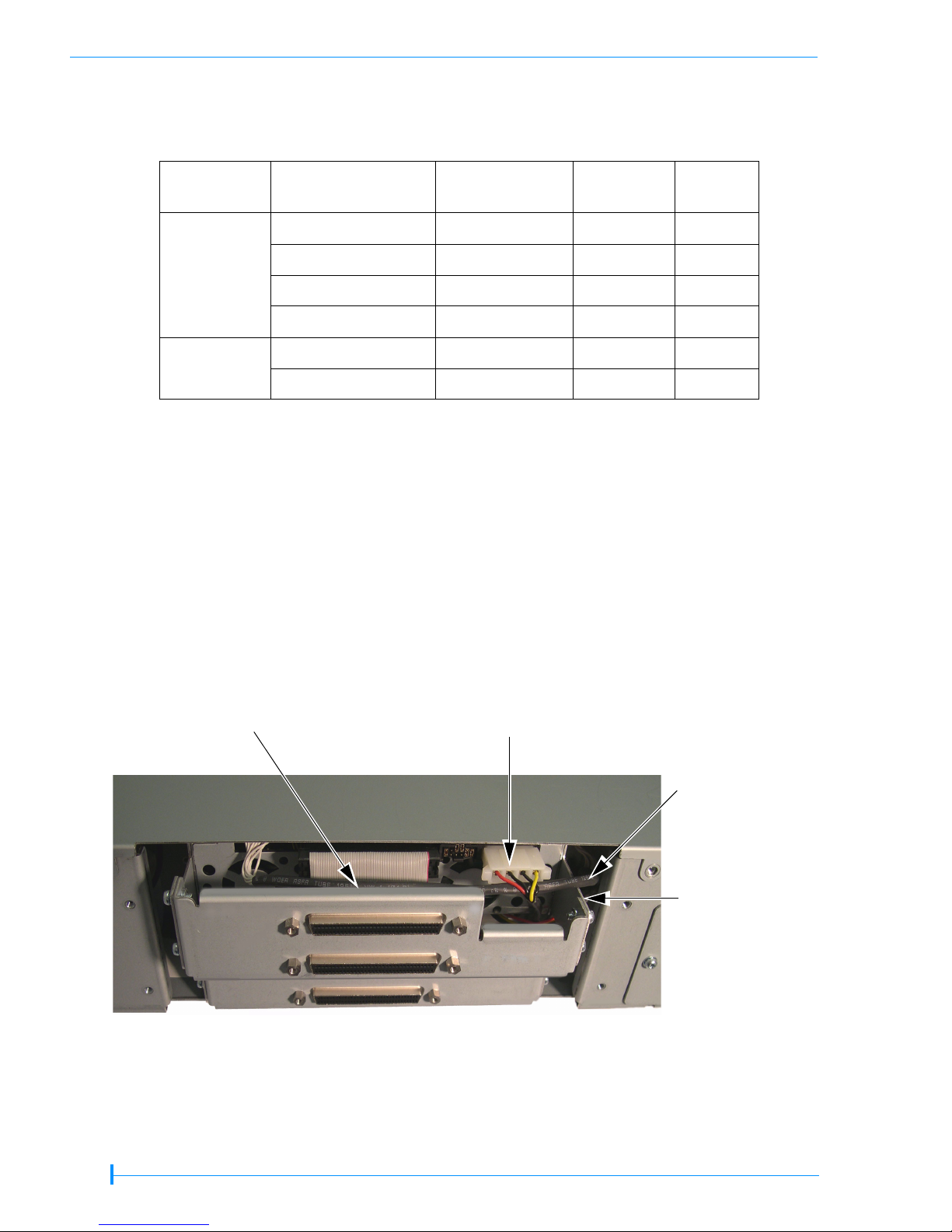
Figure 1 StorageLibrary T24 serial cable routing—full height tape drive
Serial cable (C)
Top serial
connector (not used)
Bottom serial
connector
Drive 2
Drive 1
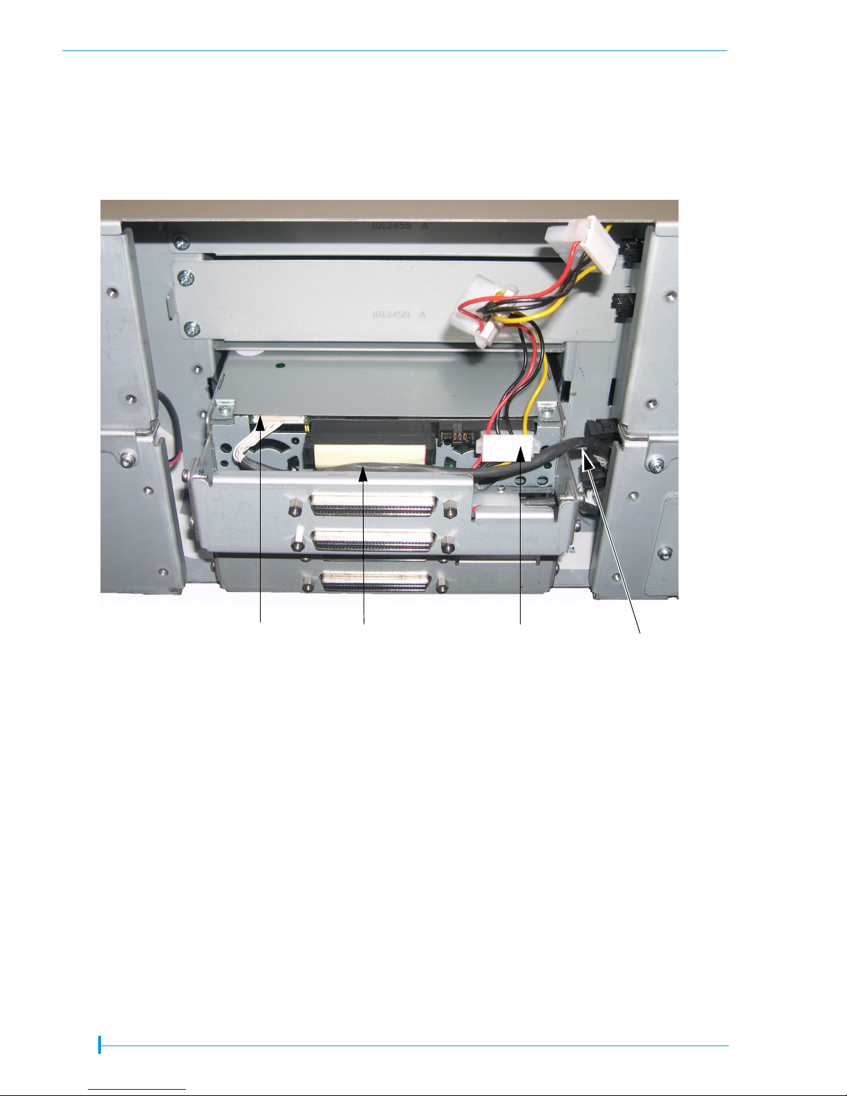
Figure 2 StorageLibrary T24 serial cable routing—half height tape drives
Middle power connector
(not used in this
configuration)
Bottom power
connector
Serial cable (C
Second serial
connector
Bottom serial
connector
Power cable (D)
Library power
connector
)
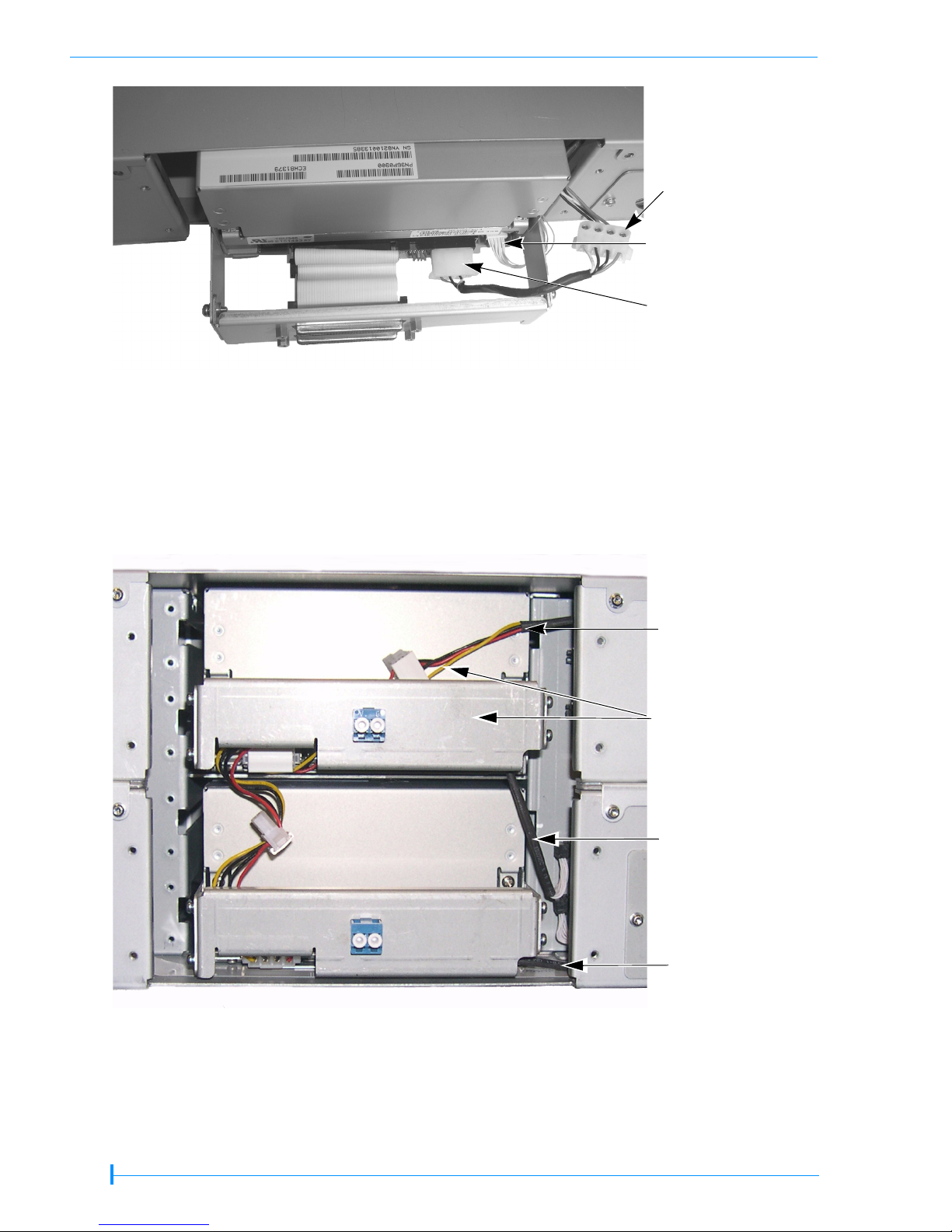
Figure 3 StorageLibrary T24 power cable routing—full height tape drive
Figure 4 StorageLibrary T24 power cable routing—half height tape drives
4 OF 28
Power cable (D)
Top power
connector (upper TD)
Library power
connector
Middle power
connector (lower TD)
Page 5

StorageLibrary T48—
StorageLibrary T48
Tape Drive
Cover Plate (P)
Half Height
SCSI configuration
StorageLibrary T48
Tape Drive
Cover Plate (P)
SCSI cover
plate (S)
SCSI cover
plate (S)
Full Height
Fibre Channel
configuration
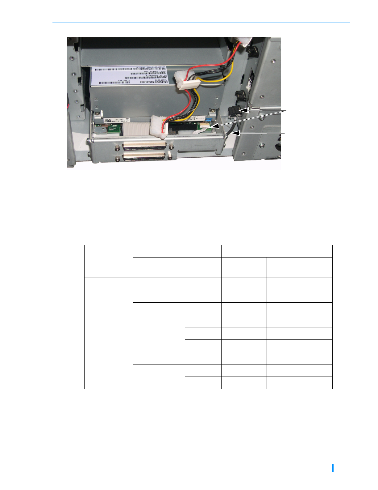
Serial cable (C)
Connect to tape
drive (white)
Connect to
library (black)
! Important
Be sure to use the serial cable (C) that came with your
replacement kit. The serial cables are specifically configured
(at the factory) for use with the individual tape drives.
5 OF 28
Page 6

Serial cable (C)
Drive 4
Drive 3
Drive 2
Drive 1
Figure 5 StorageLibrary T48 serial cable routing—full height tape drives
Drive 4
Drive 3
Top serial
connector (not used)
Third serial
connector (not used)
Second serial
connector
Bottom serial
connector
Serial cable (C)
Top serial
connector
Third serial
connector
Drive 2
Drive 1
Figure 6 StorageLibrary T48 serial cable routing—half height tape drives
Second serial
connector
Bottom serial
connector
6 OF 28
Page 7

Top power connector
(not used in this
configuration)
Third power connector
Second power connector
(not used in this
configuration)
Bottom power
connector
Figure 7 StorageLibrary T48 power cable routing—full height tape drives
Power cable (D)
Library power
connector
Power cable (D)
Library power
connector
Figure 8 StorageLibrary T48 power cable routing—half height tape drives
Top power
connector
Third power
connector
Second power
connector
Bottom power
connector
7 OF 28
Page 8

INSTALLING ADDITIONAL TAPE DRIVES
To install an additional tape drive (or tape drives), follow these steps:
1. Preparing for replacement—
a. Power off the library (press the 0 on the back of the unit)
b. Disconnect the power cord, the SCSI or Fibre Channel cable(s), and the terminator
(if one is installed).
c. Power off the host
d. Remove the tape drive cover plate (
Back of library
Screws
P). Set the plate and the screws aside.
Tap e d r i v e
cover plate (P)
Screws
Power OFF
(press the 0)
Disconnect
power cord
Figure 9 Tape drive cover plate (StorageLibrary T24 library shown)
Note: This figure shows the StorageLibrary T24 SCSI library with one half height tape
drive installed. Remove the StorageLibrary T48 tape drive cover plate (SCSI and
Fibre Channel) the same way.
2. Removing the internal cooling plates and disconnecting cables—
! Important
tape drives, but leave all empty tape drive bays covered. The
plates are required for proper cooling.
8 OF 28
Remove as many internal cooling plates as necessary to add
Page 9

a. Remove the two screws (A) holding the tape drive cooling plate (B). Remove the
plate, and discard it and the screws.
Screws (A)
Cooling plate (B)
Figure 10 StorageLibrary T24 tape drive cooling plate
b. Disconnect the power cables (
D) from all of the tape drives.
3. Installing the tape drive—
Looking inside
back of library
Retaining
tab
Single half height
tape drive (cables
removed for
clarity)
! Important
Channel tape drives in the StorageLibrary T48 library, as it does
not support mixed tape drive configurations.
Do not mix full height and half height or SCSI and Fibre
a. Locate the serial cable (
C) that came in your replacement kit and attach it to the
appropriate serial connector inside the library.
StorageLibrary T24 library serial cable connections—
Half height tape drive—see Figure 2
Tape drive Quantity
Second tape drive Top Top Dr i ve 2
Half height
Single tape drive Bottom Bottom Drive 1
Install in this
opening...
Serial
connector
Internal
label
9 OF 28
Page 10
StorageLibrary T48 library serial cable connections—
Full height tape drive—see Figure 5
Half height tape drive—see Figure 6
Tape drive Quantity
Install in this
opening...
Serial
connector
Internal
label
Fourth tape drive Top To p D riv e 4
Third tape drive Third Third Drive 3
Half height
Second tape drive Second Second Drive 2
Single tape drive Bottom Bottom Drive 1
Second tape drive Top Second Drive 2
Full height
Single tape drive Bottom Bottom Drive 1
b. While holding the cables to the side, slide the new tape drive directly into the library,
leaving it a short distance out to access the cables. Use care not to damage the cables.
c. Connect the supplied serial cable (
C) and the power cable (D) to the tape drives.
StorageLibrary T24 tape drive serial and power cable connections—
Serial—Route the serial cable (
cable as shown here; connect as shown in Figure 2 (StorageLibrary T24 HH serial
cable routing).
Power—Route the power cable through the tape drive carriers as shown here;
connect as shown in Figure 4 (StorageLibrary T24 HH power cable routing).
C) over the tape drive carrier and under the power
Press the serial cable (C) down into the
carrier to prevent catching it between
the tape drive and the library.
Power cable (D)
(route under carrier
and over serial cable)
Serial cable (C)
(route over
carrier and
under the
power cable)
Tape drive
carrier
Figure 11 StorageLibrary T24—installing additional tape drives: half height connectors
10 OF 28
Page 11

StorageLibrary T48 tape drive serial and power cable connections—
Full height tape drive:
Serial—Route the serial cable (
connect as shown in Figure 5 (StorageLibrary T48 FH serial cable routing).
Power—Route the power cable through the tape drive carriers as shown here;
connect as shown in Figure 7 (StorageLibrary T48 FH power cable routing).
C) under the tape drive carrier as shown here;
Power cable (D)
Route power cable
through tape drive
carriers
Serial cable (C)
Connect top FH
tape drive to second
internal connector.
Connect bottom FH
tape drive to the
bottom internal
connector.
Figure 12 StorageLibrary T48—installing additional tape drives: full height connectors
Serial cable (C)
connectors
Serial cable (C)
Route under
carrier.
11 OF 28
Page 12
StorageLibrary T48 tape drive serial and power cable connections—
Half height tape drive:
Serial—Route the serial cable (
as shown in Figure 6 (StorageLibrary T48 HH serial cable routing).
Power—Route the power cable through the tape drive carriers as shown here;
connect as shown in Figure 8 (StorageLibrary T48 HH power cable routing).
C) over the tape drive carrier as shown here; connect
Serial connector
Serial cable (C)
(press down into carrier
to prevent damage)
Power connector (D)
Route serial
cable over tape
drive carrier
Figure 13 Installing additional tape drives—half height connectors
d. Slide the tape drive the remaining distance into the library. Install the tape drives
from bottom to top—fill the bottom slot first, the second slot next, and so forth. Do
not skip slots. Continue adding tape drives, as needed.
12 OF 28
Page 13

4. Completing the installation—
a. Locate the tape drive cover plate (see “Reference Illustrations” on page 3). First,
remove the necessary SCSI plates (
S), then attach the tape drive cover plate (P) with
the screws you removed earlier.
! Important
drive cover plates (P) for ESD protection. Do not leave any
openings uncovered.
Do not connect the SCSI cables until after you reconfigure the
library.
If your library has... Attach this SCSI cover plate (S)...
The library requires both the SCSI cover plates (S) and the tape
Library
Tape drive
configuration
Quantity Location External drive label
two None NA
StorageLibrary
T24
Half height
one Top NA
Full height one None NA
Four None None
Three Top Drive 4
Half height
Two Top and third Drive 4 and 3
Magnum448
One Top three Drive 4, 3, and 2
Two None None
Full height
One Top Drive 2
a
This applies to both SCSI and Fibre Channel library configurations.
a
b. Reconfigure your library—You must reconfigure your library for your backup
application to recognize the new tape drive. See page 25 for instructions.
13 OF 28
Page 14

REPLACING A TAPE DRIVE (SAME CONFIGURATION)
To replace a tape drive with a different tape drive of the same configuration (half height to
half height, or full height to full height), follow these steps.
1. Preparing for replacement—
a. Power off the library (press the 0 on the back of the unit)
b. Disconnect the power cord, the SCSI or Fibre Channel cable(s), and the terminator
(if present)
c. Power off the host
d. Remove the tape drive cover plate (
Back of library
Tap e d r i v e
cover plate (P)
Screws
P). Set the plate and the screws aside.
Power OFF
(press the 0)
Screws
Disconnect
power cord
Figure 14 Tape drive cover plate (StorageLibrary T24 Fibre Channel library)
Note: This figure shows the StorageLibrary T24 Fibre Channel library with one full height
Fibre Channel tape drive installed. Remove the StorageLibrary T48 tape drive
cover plate (SCSI and Fibre Channel) the same way.
2. Removing the tape drive—
a. Pull the tape drive a short distance out of the library, then disconnect the serial
cables (
C) from the tape drive(s) that you are replacing.
b. Disconnect the power cables (
c. While holding the cables out of the way, pull the tape drive straight out of the library.
Caution
Be certain to support the tape drive as you remove it from the library.
LTO Ultrium tape drives weigh several pounds each.
d. Disconnect the serial cable from the library and discard it. Do not reuse the serial
cable.
14 OF 28
D) from all of the tape drives.
Page 15

3. Installing the new tape drive—
a. Locate the serial cable (
C) that came in your replacement kit and attach it to the
appropriate serial connector inside the library.
StorageLibrary T24 library serial cable connections—
Full height tape drive—see Figure 1
Half height tape drive—see Figure 2
Tape drive Quantity
Install in this
opening...
Serial
connector
Full height Single tape drive Bottom Bottom Drive 1
Second tape drive Top Top Dr i ve 2
Half height
Single tape drive Bottom Bottom Drive 1
StorageLibrary T48 library serial cable connections—
Full height tape drive—see Figure 5
Half height tape drive—see Figure 6
Tape drive Quantity
Install in this
opening...
Serial
connector
Internal
label
Internal
label
Second tape drive Top Second Drive 2
Full height
Single tape drive Bottom Bottom Drive 1
Fourth tape drive Top Top D riv e 4
Third tape drive Third Third Drive 3
Half height
Second tape drive Second Second Drive 2
Single tape drive Bottom Bottom Drive 1
b. While holding the cables out of the way, slide the new tape drive into the library,
leaving it a short distance out to access the cables. Use care not to damage the cables.
c. Connect the supplied serial cable (
C) and the power cable (D) to the tape drives.
StorageLibrary T24 Full Height tape drive serial and power cable connections—
Serial—Route the serial cable (
cable as shown here; connect as shown in Figure 1 (StorageLibrary T24 FH serial
cable routing).
Power—Route the power cable through the tape drive carriers as shown here;
connect as shown in Figure 3 (StorageLibrary T24 FH power cable routing).
C) over the tape drive carrier and under the power
Tape drive Quantity
Full height Single tape drive Bottom Bottom Drive 1
Install in this
opening...
Serial
connector
Internal
label
15 OF 28
Page 16

Do not use
middle connector
with full height
tape drive
Serial cable (C)
(route under carrier)
Power cable (D)
(route over carrier)
Figure 15 StorageLibrary T24—replacing existing tape drives: full height connectors
StorageLibrary T24 Half Height tape drive serial and power cable connections—
Serial—Route the serial cable (
cable as shown here; connect as shown in Figure 2 (StorageLibrary T24 HH serial
cable routing).
Power—Route the power cable through the tape drive carriers as shown here;
connect as shown in Figure 4 (StorageLibrary T24 HH power cable routing).
C) over the tape drive carrier and under the power
Tape drive Quantity
Second tape drive Top Top Dr i ve 2
Half height
Single tape drive Bottom Bottom Drive 1
Press the serial cable (C) down into the
carrier to prevent catching it between
the tape drive and the library.
Install in this
opening...
Power cable (D)
(route under carrier
and over serial cable)
connector
Serial
Internal
label
Serial cable (C)
(route over
carrier and
under the
power cable)
Tape drive
carrier
Figure 16 StorageLibrary T24—replacing existing tape drives: half height connectors
16 OF 28
Page 17

StorageLibrary T48 Full Height tape drive serial and power cable connections—
Serial—Route the serial cable (
connect as shown in Figure 1 (StorageLibrary T48 FH serial cable routing).
Power—Route the power cable through the tape drive carriers as shown here;
connect as shown in Figure 7 (StorageLibrary T48 FH power cable routing).
C) under the tape drive carrier as shown here;
Power cable (D)
Route power cable
through tape drive
carriers
Serial cable (C)
Serial cable (C)
Figure 17 StorageLibrary T48—replacing existing tape drives: full height connectors
Serial cable (C)
connectors
Serial cable (C)
Route under
carrier.
17 OF 28
Page 18

StorageLibrary T48 Half Height tape drive serial and power cable connections—
Serial—Route the serial cable (
as shown in Figure 6 (StorageLibrary T48 HH serial cable routing).
Power—Route the power cable through the tape drive carriers as shown here;
connect as shown in Figure 8 (StorageLibrary T48 HH power cable routing).
C) over the tape drive carrier as shown here; connect
Serial cable (C)
(route over
carrier)
Tape drive
carrier
Press the serial cable (C) down into the
carrier to prevent catching it between
the tape drive and the library.
Power cable (D)
(route through carriers)
Figure 18 StorageLibrary T48—replacing existing tape drives: half height connectors
d. Slide the tape drive the remaining distance into the library. Use care not to damage
the cables during this step.
4. Completing the installation—
a. Attach the SCSI cover plate (
S) and the tape drive cover plate (P) that came with
your replacement kit. See “Reference Illustrations” on page 3.
The library requires both the SCSI cover plates (S) and the tape
! Important
drive cover plates (P) for ESD protection. Do not leave any
openings uncovered.
Do not connect the SCSI cables until after you reconfigure the
library.
b. Reconfigure your library—You must reconfigure your library for your backup
application to recognize the new tape drive. See page 25 for instructions.
18 OF 28
Page 19

REPLACING A TAPE DRIVE (HALF HEIGHT TO FULL HEIGHT)
To replace a half height tape drive with a full height tape drive, follow these steps.
1. Preparing for replacement—
a. Power off the library (press the 0 on the back of the unit)
b. Disconnect the power cord, the SCSI or Fibre Channel cable(s), and the terminator
(if present)
c. Power off the host
d. Remove the tape drive cover plate (
Tap e d r i v e
cover plate (P)
Screws
P). Set the plate and the screws aside.
Back of library
Screws
Power OFF
(press the 0)
Disconnect
power cord
Figure 19 Tape drive cover plate (StorageLibrary T48 half height SCSI library)
Note: This figure shows the StorageLibrary T48 FC library with two half height tape
drives installed. Remove the StorageLibrary T24 tape drive cover plate (SCSI and
Fibre Channel) the same way.
2. Removing the cables, internal cooling plates, and tape drives—
a. Pull the tape drive a short distance out of the library and disconnect the serial
cable (
C). Repeat for all the tape drives that you are replacing.
b. Disconnect the power cables (
c. Remove the screws (
D) from all of the tape drives.
A) holding the tape drive cooling plate (B).
19 OF 28
Page 20

d. Remove the plate, and discard it and the screws.
Looking inside
back of library
Screws (A)
Cooling
plate (B)
Retaining
tab
Single half
height
tape drive
Serial
cable (C)
Power
cable (D)
Figure 20 Converting half height to full height—internal cooling plates
Note: This figure shows the StorageLibrary T48 SCSI library with one half height tape
drive installed. Remove the StorageLibrary T24 internal cooling plates the same
way.
Remove as many internal cooling plates as necessary to add
! Important
tape drives, but leave all empty tape drive bays covered. The
plates are required for proper cooling.
e. While holding the cables out of the way, remove the tape drive(s).
Caution
f. Disconnect the serial cable (
Be certain to support the tape drive as you remove it from the
library. LTO Ultrium tape drives weigh several pounds each.
C) from the library. Do not reuse this cable. If you are
replacing multiple tape drives, remove and discard the serial cables from all the tape
drives you are replacing.
20 OF 28
Page 21

3. Installing the tape drive—
! Important
a. Locate the serial cable (
appropriate serial connector inside the library.
StorageLibrary T24 library serial cable connections—
Full height tape drive—see Figure 1
Tape drive Quantity
Full height Single tape drive Bottom Bottom Drive 1
Do not mix full height and half height or SCSI and Fibre
Channel tape drives in the library. The StorageLibrary T48 does
not support mixed tape drive configurations.
C) that came in your replacement kit and attach it to the
Install in this
opening...
Serial
connector
StorageLibrary T48 library serial cable connections—
Full height tape drive—see Figure 5
Tape drive Quantity
Second tape drive Top Second Drive 2
Full height
Single tape drive Bottom Bottom Drive 1
Install in this
opening...
Serial
connector
Internal
label
Internal
label
b. While holding the cables to the side, slide the new tape drive directly into the library,
leaving it a short distance out to access the cables. Use care not to damage the cables.
c. Connect the supplied serial cable (
C) and the power cable (D) to the tape drives.
StorageLibrary T24 Full Height tape drive serial and power cable connections—
Serial—Route the serial cable (
cable as shown here; connect as shown in Figure 1 (StorageLibrary T24 FH serial
cable routing).
Power—Route the power cable through the tape drive carriers as shown here;
connect as shown in Figure 3 (StorageLibrary T24 FH power cable routing).
Tape drive Quantity
Full height Single tape drive Bottom Bottom Drive 1
C) over the tape drive carrier and under the power
Install in this
opening...
Serial
connector
Internal
label
21 OF 28
Page 22
Do not use
middle connector
with full height
tape drive
Serial cable (C)
(route under carrier)
Power cable (D)
(route over carrier)
Figure 21 StorageLibrary T24—replacing HH tape drives with a full height tape drive
StorageLibrary T48 Full Height tape drive serial and power cable connections—
Serial—Route the serial cable (
connect as shown in Figure 1 (StorageLibrary T48 FH serial cable routing).
Power—Route the power cable through the tape drive carriers as shown here;
connect as shown in Figure 7 (StorageLibrary T48 FH power cable routing).
C) under the tape drive carrier as shown here;
Power cable (D)
Route power cable
through tape drive
carriers
Serial cable (C)
Serial cable (C)
Figure 22 StorageLibrary T48—replacing HH tape drives with full height tape drives
22 OF 28
Page 23
d. Slide the tape drive the remaining distance into the library.
4. Completing the installation—
Serial cable (C)
connectors
Serial cable (C)
Route under
carrier.
a. Attach the SCSI cover plates (
S) and the tape drive cover plate (P) that came with
your replacement kit. See “Reference Illustrations” on page 3.
If your library has... Attach this SCSI cover plate (S)...
Library
Tape drive
configuration
Quantity Location External drive label
two None NA
StorageLibrary
T24
Half height
one Top NA
Full height one None NA
Four None None
Three Top Drive 4
Half height
Two Top and third Drive 4 and 3
Magnum448
One Top three Drive 4, 3, and 2
Two None None
Full height
One Top Drive 2
a
This applies to both SCSI and Fibre Channel library configurations.
a
23 OF 28
Page 24

! Important
b. Reconfigure your library—You must reconfigure your library for your backup
application to recognize the new tape drive. See page 25 for instructions.
The library requires both the SCSI cover plates (S) and the tape
drive cover plates (P) for ESD protection. Do not leave any
openings uncovered.
Do not connect the SCSI cables until after you reconfigure the
library.
24 OF 28
Page 25
RECONFIGURING THE LIBRARY AND RESUMING OPERATION
RECONFIGURING THE LIBRARY
In order for the library to recognize the new tape drive, you must set the tape drive
configuration to match the tape drives that are installed in the library.
Note: Do not connect the SCSI cables at this time.
To set tape drive configuration:
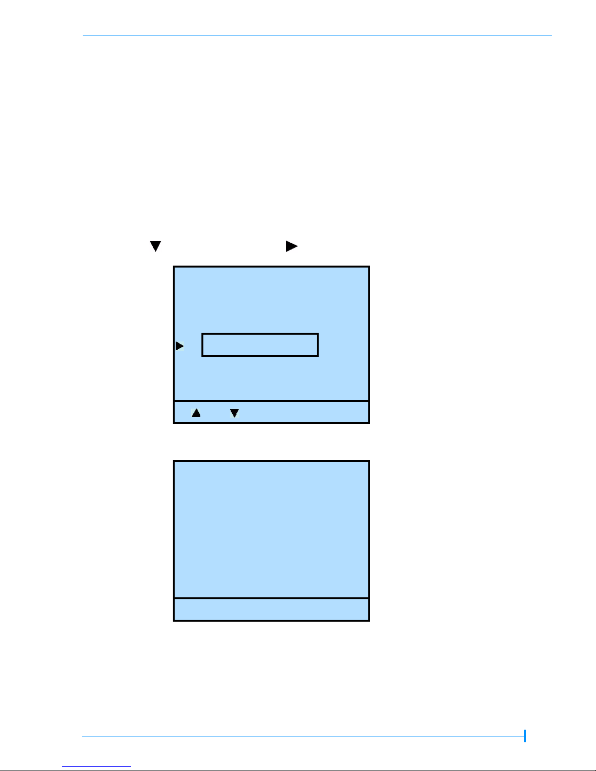
1. At the Home screen, press Drive.
If necessary, enter the operator panel password (see page 72).
2. Press until the selection arrow ( ) points to Drive Configuration.
Drive
Drive ID
Drive SCSI ID
3. Press Select.
Drive Configuration
1: HP LTO-2 HalfHigh
2: HP LTO-2 HalfHigh
3: no drive
4: no drive
Drive Configuration
Library SCSI Bridge
Select Back
Modify OK
Note: The library lists “no drive” only if there is no room for more tape drives. For
example, in the above screen, the StorageLibrary T48 library has two half height
tape drives. The four tape drive number is for four half height tape drives.
25 OF 28
Page 26
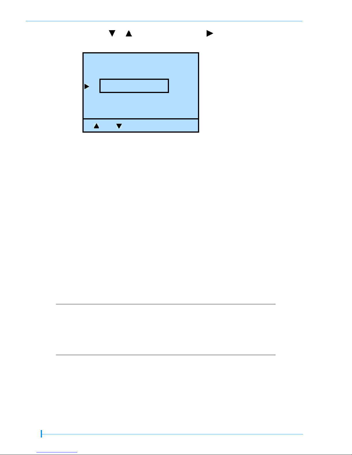
4. Press Modify. Press or until the selection arrow ( ) points to the desired
configuration. Press Select.
Select Drive 1
HP LTO-2 HalfHigh
IBM LTO-3 FullHigh
Select Back
Note: This menu option requires input for all of the tape drives installed in the library. If
you press “Back” before configuring all the tape drives, the configuration
selection will not change.
5. Press OK.
6. Repeat the process for each tape drive installed.
7. Press Back (as needed) to return to the Home screen.
RESUMING OPERATION
1. Power the library off (press the 0 on the back of the unit—after setting the new tape
drive configuration).
2. Connect the interface cables.
Connect the Fibre Channel cable (or cables if you installed more than one Fibre Channel
tape drive).
or...
Connect the SCSI cable (or cables if you installed more than one tape drive) and a
terminator (if needed).
! Important
You must install a terminator on the device at the physical end of the SCSI bus. If
one of the tape drives in the library terminates the SCSI bus, you must install the
required terminator on one of the tape drive’s SCSI connectors.
Both LTO-2 and LTO-3 tape drives require an Ultra 3 or LVD
160 terminator to function properly on the SCSI bus. An
inadequate terminator will result in various SCSI bus issues,
including bus hangs and Read/Write failures. See the individual
Product Manuals at www.tandberg.com for detailed
information.
If there are additional devices on the SCSI bus, ensure that only the device at the
physical end of the bus is terminated.
26 OF 28
Page 27

The library communicates with the host through the SCSI interface of one of the
tape drive via the Automation Drive Interface (ADI) serial interface.
See the tape drive’s Product Manual for tape drive information.
See Automation/Drive Interface – (ADC) for ADI information.
3. Reconnect the power cord and power on the library (press the
then power on the host.
The library is now ready to resume operation. The new tape drive defaults to the
following SCSI IDs:
Library Tape Drive Configuration SCSI ID
Single half height tape drive 3
StorageLibrary
T24
StorageLibrary
T48
Two half height tape drives
Full height tape drive 3
Single half height tape drive 3
Four half height tape drives
Single full height tape drive 3
Upper tape drive 4
Lower tape drive 3
Top tape drive 6
Third tape drive 5
Second tape drive 4
Bottom tape drive 3
I on the back of the unit),
! Important
Two full height tape drives Top tape drive 4
Bottom tape drive 3
You may need to reconfigure your backup application to
recognize the new tape drive. Refer to your application’s
documentation for instructions.
27 OF 28
Page 28

CONFIRMING THE INSTALLATION
You may want to perform a few load and unload operations and back up several
megabytes of data to ensure that the library and the newly installed tape drive (or tape
drives) are communicating correctly.
Detect the library
Use LibTool to
View the library’s cartridge inventory
Move tapes into and out of the tape drive
Detect the tape drive
Use LTOTool to
Perform a Read/Write test
Download and install the tools from www.tandberg.com The readme file that
accompanies the program (or the online help for the Windows version) provides
instructions for using the tools.
For questions regarding software configuration, operation (including how to perform a
backup operation), or installation—contact your software provider.
28 OF 28
 Loading...