

Page 1
Owner’Owner’
Owner’
Owner’Owner’
s Mans Man
s Man
s Mans Man
ualual
ual
ualual
Model Numbers:
TT
CP-25, TCP-25, T
T
CP-25, T
TT
CP-25, TCP-25, T
TT
CP-381CP-381
T
CP-381
TT
CP-381CP-381
PUMPSPUMPS
PUMPS
PUMPSPUMPS
CP-210CP-210
CP-210
CP-210CP-210
P/N 25121
Date 05-12-01
TCP-210
ISM, Inc. • 1028 4th Street SW • Auburn, WA 98001 • Phone: (253) 333-1200 • Fax: (253) 333-1212
www.tanakapowerequipment.com custsvc@tanaka-ism.com
Supplier To The Outdoor Power Equipment Industry
Page 2

t
TCP-25/210/381
Owner’s Manual
Before using this unit:
• Read the operator’s manual carefully.
• Check that the cutting equipment is correctly assembled
• Start the unit and check the carburetor adjustment.
Always wear eye, head and ear protectors
when using this unit.
and adjusted.
See “Maintenance”.
The engine exhaust from this product
contains chemicals known to the State
of California to cause cancer, birth
defects and other reproductive harm.
WARNING
Read, understand and follow all warnings and
instructions in this manual and on the unit.
Explains choke position. Upper sign indicates
choke closed and the lower fully open.
It is important that you read, fully understand
and observe the following safety precautions and
warnings. Careless or improper use of the uni
may cause serious or fatal injury.
www.tanakapowerequipment.com 1 custsvc@tanaka-ism.com
Page 3
TCP-25/210/381
Owner’s Manual
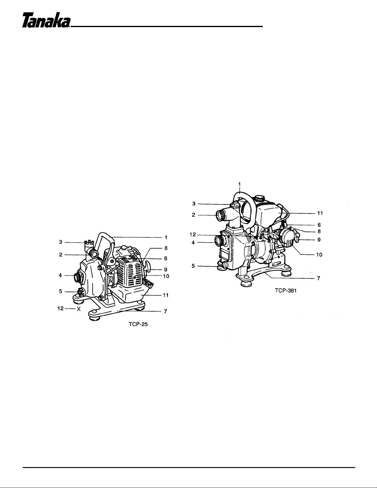
1. What is What?
Since this manual covers several models, there may be some difference between pictures and your unit.
Use the instructions that apply to your unit.
1. Carrying Handle
2. Delivery Port
3. Priming Plug
4. Suction Port
5. Drain Plug
6. Throttle Lever
7. Base
8. Choke Lever
9. Recoil Starter
10. Air Cleaner
11. Fuel Tank
12. Fuel Cock
www.tanakapowerequipment.com 2 custsvc@tanaka-ism.com
Page 4

TCP-25/210/381
Owner’s Manual
2. Warnings and Safety Instructions.
Before operation
• Protection is required for head, eyes, ears, hands and feet. Wear a suitable hard hat, goggles, ear
covers, heavy gloves and safety shoes.
• Dress properly, do not wear loose clothing or jewelry that could become caught in moving parts of the
unit.
• Never let a child or inexperienced person operate the machine.
• Be sure to check bolts and other fasteners to see if any of them have become loose or are missing.
On fuel
• Never operate the engine with gasoline only.
• This engine uses a fuel mix of 25-50 parts regular gasoline to 1 part of two-stroke oil. The fuel should
be premixed prior to pouring into the fuel tank. It is recommended a quality two-stroke oil be used in
the fuel mix.
• Failure to mix oil with gasoline will result in seizure and severe damage to the engine.
• Do not use gasoline containing alcohol or gasohol.
• Do not smoke when the fuel is supplied, and when you are working with the machine.
• Do not touch tank cap or fill the fuel tank while the engine is running or still warm. The fuel should be
poured into the fuel tank when the engine is cold.
• Never start the machine without priming water in the pump. It will cause serious damages to the
engine and the pump; the manufacturer cannot guarantee in this case.
• Care must be taken to ensure that an air tight connection is made between the female unions, and the
male pump stubs. An air leak at either union will greatly reduce the pump efficiency, or no water is
pumped at all.
• A strainer should always be used on the suction hose, to prevent debris from entering the pump body,
and causing possible damage to the impeller.
During operation
• The unit should be operated in well ventilated area.
• Never carry the unit with the engine running.
• For safety, the unit should not be started without priming water.
• Do not pump oil etc. which is flammable.
• After the pumping of seawater, chemical fluid or urine, wash the pump with fresh water.
WARNING!
Indicates a strong possibility of severe personal injury or loss of life, if instructions are not followed.
CAUTION!
Indicates a possibility of personal injury or equipment damage, if instructions are not followed.
NOTE!
Helpful information for correct function and use.
www.tanakapowerequipment.com 3 custsvc@tanaka-ism.com
Page 5

TCP-25/210/381
3. Assembly Procedure
Hose to pump connection. (Fig. 1-1)
Care must be taken to ensure that tight connection is made
between the female unions, and the male pump stubs.
NOTE!
An air leak at either union will greatly reduce the pump efficiency or
no water is pumped at all.
Owner’s Manual
Strainer (Fig. 1-2)
CAUTION!
A strainer should always be used on the suction hose, to prevent
debris from entering the pump body, and causing possible damage
to the impeller.
4. Operating Procedures
Fuel
• Always use branded 89 octane unleaded gasoline.
• Use Tanaka two-cycle oil or a quality two-cycle oil at mixing
ratio of 25-50:1 (Gasoline (A) : Oil (B)), only for the state of
California at 50:1.
• Never use multi-grade oil (10 W/30) or waste oil.
• Always mix fuel and oil in a separate clean container.
• Always start by filling half the amount of fuel, which is to be
used. Then add the whole amount of oil. Mix (shake) the
fuel mixture. Add the remaining amount of fuel.
Mix (shake) the fuel-mix thoroughly before filling the fuel
•
tank.
Fueling
WARNING!
• Always shut off the engine before refueling.
• Slowly open the fuel tank, when filling up with fuel, so that possible over-pressure disappears.
• Tighten the fuel cap carefully, after fueling.
• Always move the unit at least 3 m (10 ft.) from the fueling area before starting.
Before fueling, clean the tank cap area carefully, to ensure that no dirt falls into the tank.
Make sure that the fuel is well mixed by shaking the container, before fueling.
www.tanakapowerequipment.com 4 custsvc@tanaka-ism.com
Page 6

g
TCP-25/210/381
Priming (Fig. 2-2)
It is necessary to prime the pump before the initial usage. This is done
by filling the pump body with water via the priming plug on the top of
the pump housing.
CAUTION!
Never start the machine without priming water in the pump. It will
cause serious damages to the engine and pump parts, the
manufacturer cannot
uarantee in this case.
Owner’s Manual
Starting (Fig. 2-3, 3 B)
*Open the Fuel cock (3). (TCP-381, Fig. 2-3B)
1. Set choke lever to CLOSED position (1).
2. Set the throttle lever to approximately 1/2 throttle opening (2).
3. Pull recoil starter briskly, taking care to keep the handle in your grasp and not allowing it to snap back. (Fig. 2-4)
4. When you hear the engine wants to start, return choke lever to RUN position (open). Then pull recoil starter
briskly again.
5. After starting the engine, allow it to warm up for 2-3 minutes before subjecting it to any load.
Running
If water does not come out smoothly while using, stop the engine and wash the suction strainer. (Fig. 2-5)
CAUTION!
Do not pump oil etc. which is flammable
NOTE!
After the pumping of seawater, chemical fluid or urine, wash the pump with fresh water.
Stopping (Fig. 2-6, 6B)
When the engine is to be stopped, gradually decrease the engine speed to an idle, and then stop the engine.
The engine is stopped, by completely raising the throttle lever.
www.tanakapowerequipment.com 5 custsvc@tanaka-ism.com
Page 7

TCP-25/210/381
Owner’s Manual
www.tanakapowerequipment.com 6 custsvc@tanaka-ism.com
5. Maintenance.
Water pump (Fig. 3-1)
All water in the pump should be drained from the housing, by means of the
drain plug. Water left in the pump housing may cause damage by corrosion;
there is also the danger of *freeze-up" damage in cold weather.
NOTE!
When the pump is used for the pumping of seawater, chemical fluid, or water
which may contain any type of contaminant, the pump should always be "run
through" with clean water prior to storage.
Air filter (Fig. 3-2)
The air filter must be cleaned from dust and dirt in order to avoid:
• Carburetor malfunctions.
• Starting problems.
• Engine power reduction.
• Unnecessary wear on the engine parts.
• Abnormal fuel consumption.
Clean the air filter daily or more often if working in exceptionally dusty areas.
Cleaning the air filter
Remove the air filter cover and the filter. Rinse it in warm soap suds. Check that
the filter is dry before reassembly. An air filter that has been used for some time
cannot be cleaned completely. Therefore, it must regularly be replaced by a new
one. A damaged filter must always be replaced.
NOTE! (TCP - 25)
Saturate the element in 2-cycle oil or the equivalent. Squeeze the element to
distribute the oil completely and to remove any excess oil.
Spark plug (Fig. 3-3)
The spark plug condition is influenced by:
• An incorrect carburetor setting.
• Wrong fuel mixture (too much oil in the gasoline)
• A dirty air filter.
• Hard running conditions (such as cold weather).
These factors cause deposits on the spark plug electrodes, which may result in
malfunction and starting difficulties. If the engine is low on power, difficult to
start or runs poorly at idling speed, always check the spark plug first. If the spark
plug is dirty, clean it and check the electrode gap. Readjust if necessary. The
correct gap is 0.6 mm. The spark plug should be replaced after about 100
operation hours or earlier if the electrodes are badly eroded.
NOTE!
In some areas, local law requires using a resistor spark plug to suppress ignition
signals. If this machine was originally equipped with resistor spark plug, use same
type of spark plug for replacement.
Muffler (Fig. 3-4)
Remove the muffler and clean out any excess carbon from the exhaust port or
muffler inlet from time to time in order to avoid power-loss.
Page 8

Maintenance schedule
Below you will find some general maintenance instructions.
For further information please contact your service dealer.
Daily maintenance
• Clean the exterior of the pump.
• Check that nuts and screws are sufficiently tightened.
Weekly maintenance
• Check the starter, especially cord and return spring.
TCP-25/210/381
Owner’s Manual
• Clean the exterior of the spark plug,
• Remove the spark plug and check the electrode gap. Adjust it to 0.6 mm (.024’), or
change the spark plug.
• Clean the cooling fins on the cylinder and check that the air intake at the starter is
not clogged.
• Clean the air filter.
Monthly maintenance
• Rinse the fuel tank with gasoline, and clean fuel filter.
• Clean the exterior of the carburetor and the space around it.
• Clean the fan and the space around it.
www.tanakapowerequipment.com 7 custsvc@tanaka-ism.com
Page 9

TCP-25/210/381
Owner’s Manual
6. Technical Data
Model TCP-25/210 TCP-381
Engine
Type High torque 2-cycle, single cylinder
Size 22 ml 51 ml
Max Power 0.75 kW / 8,000 min-1 1.65 kW / 5,500 min-1
Carburetor System Walbro diaphragm Float type
Ignition System Electronic
Spark Plug NGK BPM-7A or BPMR-7A NGK BM-6A or BMR-6A
Fuel Tank Capacity 0.75 l 1.2 l
Pump
Max Capacity 120 l / min 300 l /min.
Max suction height 8 m 5 m
Max delivery height 35 m 40 m
Connection diameter 1” (25.4 mm) 1.5” (38 mm)
Dry weight 5.1 kg 9.5 kg
Overall dimensions (L x W x H) 287 x 219 x 288 mm 398 x 300 x 382 mm
Sound pressure level (dB(A)) 85.1 91.1
Sound power level (dB(A)) 91.9 98.3
NOTE : Equivalent noise level/vibration level are calculated as the time-weighted energy total for
noise/vibration levels under various working conditions with the following time distribution :
½ idle, ½ full speed.
! All data subject to change without notice.
!
!
www.tanakapowerequipment.com 8 custsvc@tanaka-ism.com
Page 10

We, Tanaka Kogyo Co.,Ltd.,3-4-29 Tsudanuma,Narashino,Chiba,Japan
Declare under our sole responsibility that the product, engine pump model TCP-25,381
to which this declaration relates is in conformity with the essential safety requirements of directives.
TCP-25/210/381
Owner’s Manual
Declaration of conformity
89/392/EEC, 91/368/EEC, 93/44/EEC, 93/68/EEC, EMC89/336/EEC
The following standards have been taken into consideration. ISO 3864, (EN-292-2)
Manufactured at: Chiba, Japan Serial No. up from V001001
Signature:
Position: Vice president
www.tanakapowerequipment.com 9 custsvc@tanaka-ism.com
 Loading...