

Tamron BRONICA RF645 Owner Manual

1
RF645
Thank you for your purchase of the Bronica RF645 medium format rangefinder camera.
Incorporating the best of Bronica's know-how and technological expertise, the Bronica
RF645 achieves a new dimension in compactness as the world's first medium format 6 x 4.5
rangefinder camera to feature interchangeable lenses, and comes with a superb line up of
lenses to take full advantage of the rangefinder camera. The RF645 employs manual film
advance lever and dual-image superimposing rangefinder focusing for maximum user control where it counts, while enhancing handling ease with Program AE, automatic shutter
cocking via a motor designed for the maximum enjoyment of photography in mind.
The features and handling procedures described in this owner's manual are based on use of
the Bronica RF645 in combination with the Zenzanon RF65mm f/4 standard lens. To obtain
best results from your new camera, please read this instruction manual carefully before use.
With proper care and handling, the unit will continue to provide pleasure and performance
for many years to come.

Special Features of the Bronica RF645
Nomenclature
1. Getting Started
1-1 Loading batteries
1-2 Attaching and detaching lens
1-3 Attaching strap
1-4 Attaching the proper diopters adjustment lens
2. Preparing to Shoot
2-1 Checking the battery capacity
2-2 Loading film
2-3 Setting the film speed
2-4 Exposure counter, Film memo holder,
How to remove a used roll of film
3. Shooting
3-1 Main switch
3-2 Viewfinder, Holding the camera
3-3 Shutter release button,Viewfinder display
3-4 Exposures
3-4-1 Shutter dial and lens aperture operation
3-4-2 Exposure Metering system
3-4-3 Exposure control modes
1) Program AE mode
2) Aperture-priority AE mode
3) Manual exposure control
3-4-4 Exposure compensation
3-4-5 AE lock
3-5 Focusing
3-6 Automatic parallax compensation
4.Other features
4-1 Multiple exposures
4-2 Self-timer
4-3 Electronic Flash photography
4-4 Long exposure photography
4-5 Infrared photography
4-6 Depth of Field
5. Troubleshooting
6. References
7. Specifications
8. Preliminary checklist
9. Enduring years of enjoyment through proper care and handling
3, 4
5, 6
6, 7
7, 8
8
8
9
9, 10,11
11
12, 13
12
13
13, 14
14, 15
15, 16
16
17, 18
17
17
18
18, 19
19
19, 20
20
20, 21
21
22, 23
23
23
24
25, 26,27
28
29, 30
31, 32
32, 33
2
Contents Page

3
Special Features of the Bronica RF 645
·A medium format coupled-meter rangefinder camera.
The Bronica RF 645 is a very compact and lightweight camera with a picture area approximately 2.7 times larger than the 35mm format. The superior portability and versatility of
this model compared with other medium format cameras ushers in an entirely new world of
photographic possibilities.
·The remarkable lens shutter system
The electronically controlled #00 type lens shutter system developed for the Bronica RF 645
commands precise shutter speed control and automatic cocking, as well as aperture control
incorporated within the shutter unit. The interface between the main camera body and the
lens are conducted by means of a series of electronic contracts, resulting in high precision
operation compared with conventional systems operated by mechanical couplers. The
highly advanced lens shutter system is impressively stable and free of jolts caused by shutter shock, while it ensures synchronization with an electronic flash at any shutter speed
allowing sophisticated flash photography.
·Automatic light shielding curtain engaged during lens interchange.
A lens shutter camera with interchangeable lens capability would normally require a light
shielding curtain to be activated manually prior to detachment of the lens. The Bronica RF
645 had made such complex and awkward steps unnecessary, enabling photographers to
focus on the shooting itself. In conjunction with the lens detachment operation, the light
shielding curtain automatically covers the film aperture and locks into place. When the next
lens is mounted on the camera, the curtain automatically opens to prepare the camera for
the next shooting.
·Hi-tech magnesium alloy Thixmolding
The top cover of the Bronica RF 645, a lightweight and extremely sturdy camera, is manufactured with an advanced Thixmolding technique. This technology enables a hard and rigid
magnesium alloy to be molded into intricate and complex forms required to hold and protect internal mechanism with precision in various, at times even adverse, operating conditions.
·Rear cover design provides sophisticated controls with easy access and handling.
Switches and dials on the rear cover are grouped together on the rear cover for easy handling and to enable confirmation of settings at a glance, an extremely important feature for
use in the hands of serious photographers.

4
Special Features of the Bronica RF 645
·Shooting parameters of the camera are clearly indicated on the internal viewfinder
display panel.
An oversized LCD panel is installed inside the viewfinder to display constantly updated
shooting status data such as shutter speed, lens aperture, AE lock setting, exposure compensation setting, correct exposure setting and exposure deviations of manually set exposure
values and so on.
·Easy AE lock method with continuous AE lock memory system
The AE lock feature of the Bronica RF 645 stores an exposure value into memory for an
extended time without canceling it at a shutter click. The metered and stored exposure
value can then be modified by the shutter speed and aperture combination variations, or
even by compensating the stored exposure with exposure bracketing technique.
Note: Repeated activation of the AE lock memory may be limited by the remaining
battery capacity.
Also, the AE lock memory will be automatically cancelled if the power is switched off or
camera is left unused for five minutes.
·The dedicated automatic flash unit that cross-couples with the AE setting on the
camera.
The dedicated AE flash unit, the Bronica Speedlight RF 20, specially designed for the RF645
camera body, is coupled with the camera control system. The unit utilizes the electronic
contracts of the hotshoe on the camera to transmit and receive lens aperture values, the
aperture control signals and other controls data, enabling the flash unit to compensate for
the flash illumination by a half stop within -3 to ±2 exposure compensation range.

5
Nomenclature
Shutter speed dial
Film advance lever
Shutter release button
Shutter speed dial lock release button
Hotshoe
Strap lugs
Rear cover lock release
Selftimer indicator
Lens lock release button
Fiber thread
Lens
Lens hood attachment
Index
Focusing ring
Depth of field scale
Distance scale
Aperture ring
Exposure meter window
Finder
Light intake window
Rangefinder window
Exposure compensation
dial scale
Exposure compensation
dial index
Exposure compensation dial
Selftimer indicator
Multiple-exposure (ME)
button
Selftimer starting
button
Viewfinder eyepiece
Rubber eyecup
Film type
display window
Film memo holder
Strap lugs
Spool holder
Lens
Film speed setting dial
lock release button
Battery chamber
lock release
Film speed setting dial
Film speed dial index
Trip od soc ke t
Battery chamber
Spool holder
Main switch
AE lock button

6
Nomenclature
Lens mounting index
(camera body)
Rangefinder
coupling roller
Electronic contacts
(camera body)
Light shielding curtain
Flash synch terminal
Lens Lock pin
Lens lock release button
Rear cover
Pressure plate
Film spool shaft lock
release button
Spool holder
Film start alignment mark
Film type selection lever
Printed circuit cable
Film pressure spring
Light shielding curtain
1. Getting Started 1-1 Loading Batteries
The RF645 will not function without batteries loaded.
1. Appropriate batteries
Load two CR2 type 3-volt lithium battery cells.
2. Open the battery chamber cover
Pull down on the battery chamber lock release and the cover
will swing open.
3. Insert batteries
Insert two cells of the same type of batteries in the same direction as shown in drawing, directing the plus (+) side toward the
inside chamber.
4. Close the battery chamber cover
Close the chamber cover and make sure the cover is securely
locked. A loosely locked cover may open and drop the batteries in the middle of a shooting session.

7
1. Getting Started 1-1 Loading Batteries
5.Battery Checking
Battery status, the proper battery positioning of the loaded
batteries, and the remaining battery power, must be checked
prior to operation of the camera.
Turn on the main switch and press lightly on the shutter speed
dial. An LCD indicator lights up on the left side of the
viewfinder field to indicate the operational status of the cam
era. As long as a "dead battery" mark does not appear on the
LCD, the battery is properly loaded and the battery power is
sufficient for shooting.
* When "dead battery" mark starts to blink on the LCD, replace
the batteries with a new set. Low battery capacity may cause
the camera to malfunction.
* If the LCD does not light up or switches off shortly after
depressing the shutter release button, the batteries must be
replaced with new ones.
* Do not use different brands or old and new batteries
together. Such improper use of batteries will shorten battery
life and may cause battery leakage or even explosion.
1. Getting Started 1-2 Attaching and detaching the lens
1-2-1 Attaching the Lens
1. Rotate the rear lens cap of the lens counter-clockwise about
70º, and lift it off when it comes to a mechanical stop.
2. Align the lens mounting index on the lens barrel with its
counterpart on the camera body. Place the lens into the lens
mount on the camera body, and then rotate the lens barrel
clockwise until it clicks to a stop. Make sure the lens is locked
in position before using.
Note: Do not touch the electronic contacts, the rangefinder coupling
roller, or the light shielding curtain located around and behind the
camera mount section. Contact with these may cause damage
and/or leave stains on vital systems, leading to malfunctioning of the
camera.
1-2-2 Detaching the Lens
1. Depressing the lens lock release button, rotate the lens barrel
counter-clockwise, until it comes to a mechanical stop.
2. Pull out the lens barrel from the mount of the camera.

8
1. Getting Started 1-2 Attaching and detaching the lens
Note 1: The 65mm and the 100mm viewframes in the viewfinder are automatically
switched as the respective lenses are attached.
Note 2: When mounting the 45mm lens, insert the dedicated viewfinder into the accessory
hotshoe on the camera body. Refer to the instruction manual of the 45mm lens for
more information.
Note 3: When attaching or detaching lenses, do not use excessive force to rotate or twist
the lens.
Note 4: Never attempt to detach the lens while the shutter is open in B (bulb) shooting.
Note 5: This camera employs a lens shutter, so normally the film would be improperly
exposed when changing lenses. To prevent this, a light shielding curtain is automatically drawn out by the lens detaching action, covering and protecting the film.
Do not press or touch this curtain with fingers or sharp objects.
1. Getting Started 1-3 Attaching strap
1. Getting Started 1-4 Attaching the proper diopter adjustment lens
1-3 Attaching the Strap
Three camera strap lugs are provided with this camera. To carry the
camera in a horizontal position, attach the strap to the upper lugs on
both sides. To suspend the camera in a vertical position, use the
upper and lower lugs on the right side of the camera body. Follow
the procedure illustrated above to thread the strap through the lugs
and rings.
Note: Make sure the strap is properly attached to the lugs or the
camera may be accidentally dropped.
1-4 Attaching the Proper Diopter Adjustment Lens
1. A set of nine viewfinder eyepiece lenses are prepared as optional
accessories, from -5 to ±3 diopter, including the normal eyepiece lens
of -1 diopter that comes attached to the camera.
2. Detach the rubber viewfinder cup as shown above, and slide the
standard viewfinder eyepiece lens out from the eyepiece frame.
3. Replace the proper diopter adjustment eyepiece lens by sliding it
into the eyepiece frame. Attach the rubber eyecup.

9
2. Preparing to Shoot 2-1 Check battery capacity
2-1 Check Battery Capacity
The Bronica RF 645 requires a set of batteries to function, since the
camera employs an electronically controlled shutter.
1. Check the battery level before each shooting session.
2. Turn on the main switch and lightly press the shutter release
button while looking through the viewfinder. The battery
power is at a satisfactory level for shooting if the LCD on the
left side of the viewfinder turns on and the battery warning
mark "(insert)" does not appear.
Note 1: Approximately 100 rolls of 120 type film can be shot on a
fresh set of batteries before the batteries must be replaced (under
Bronica manufacturer test conditions.)
Note 2: Replace depleted batteries with new ones as soon as the battery warning mark begins to blink on the LCD. Low battery capacity
can cause the camera to malfunction.
Note 3: If the LCD does not light up or switches off shortly after
depressing the shutter release button, it is time to replace the battery
with new ones.
2. Preparing to Shoot 2-2 Loading Film
2-2 Loading Film
1. Choose a suitable film. The Bronica RF 645 can take either
120 or 220 film type. 120 type of film with light shielding back
paper takes 16 frames to a roll, while the 220 type without back
paper takes 32 frames to a roll. To load the film, open the rear
camera cover and set the film type selection lever to either 120
or 220 position according to the film to be loaded. Make sure
that the film type display window on the camera back shows
the number you set on the lever.
Note 1: Take the cover sheet attached to the film gate section of the
camera off before loading the very first roll of film you use. The cover
sheet is provided to protect the light shielding curtain.
Note 2: When loading film, first attach a lens on the camera body so
that the light shielding curtain opens. This precaution will protect the
light shielding curtain from any accidental damage.
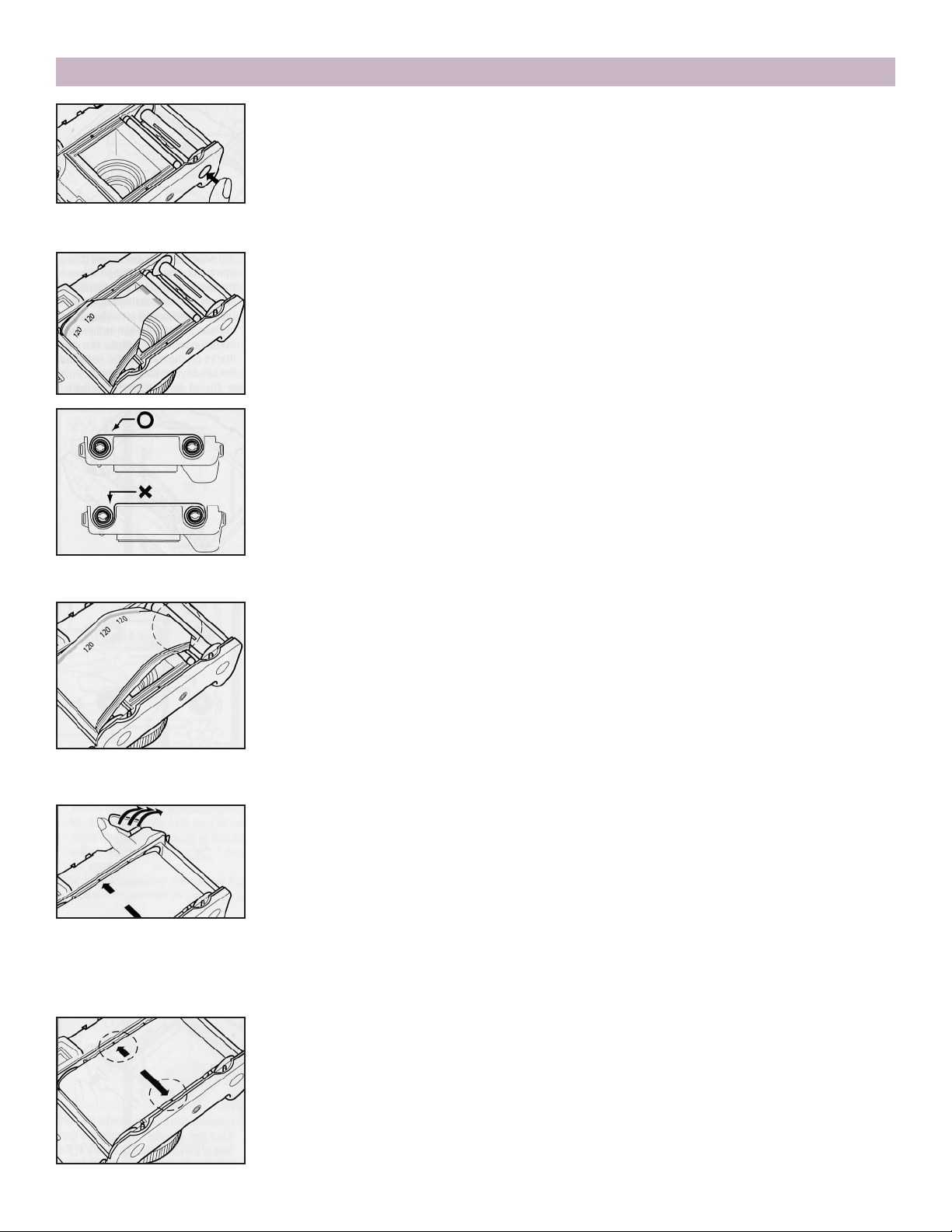
2. Depress both left and right side film spool shaft lock buttons
with the camera back open. The shafts pop downward from
the bottom of the camera and are identified by red rings.
10
2. Preparing to Shoot 2-2 Loading Film
3. Install the film take-up spool in the right hand film chamber, align-
ing the key-hole of the spool shaft of the camera. Push up the protruding film spool shaft into the bottom plate of the camera until it
locks into position.
4. Load a fresh roll of film into the left hand film chambers as illustrat-
ed in the drawing. Ensure that the film leader rolls off the outer edge
as shown instead of the inside edge of the film chamber. The inside
black surface of the leader must face outward coming out of the
chamber. If it faces inward, roll back the film, turn the roll upside
down and then reload into the film chamber. Push the fresh film
spool into the bottom of the camera.
5. Roll out the film leader and insert the leading edge into the slit of
the take-up spool shaft as far as possible.
Note: When a take-up spool is already installed in the righthand film chamber, 2. and 3. procedures described above are
not necessary.
6. Advancing the film gradually with short repeated strokes of the
film advance lever, check if the film leader is skewed on the take-up
spool. When both film leader edges are evenly positioned between
spool flanges, the film is properly wound. If one leader edge is rolling
upward on one spool flange, remove the spools and roll back the film
leader entirely before reloading it correctly.
7. Once the film leader is properly secured in place, advance the film
further until the film arrows align with the film start marks on the
camera. Do not wind the film beyond the start marks.
Note: Do not get confused by the dotted line printed on the leader
paper of the 220 type of film right in front of the real starting arrow
mark for the start mark itself.
 Loading...