

TAMKO Marquee Railing User Manual
INSTRUCTION MANUAL
®
PREPARATION & TOOL CHECKLIST
BEFORE YOU BEGIN:
IMPORTANT PRODUCT SAFETY AND PRE-INSTALLATION INFORMATION
FAILURE TO FOLLOW THESE INSTRUCTIONS MAY LEAD TO AN UNSAFELY INSTALLED PRODUCT AND WILL ADVERSELY AFFECT
COVERAGE UNDER THE LIMITED WARRANTY. The following installation instructions are provided to guide you through the installation
process of the Marquee
recommends that all designs be reviewed by a licensed architect, engineer or local building official before installation to ensure that they are safe
and in compliance with local building code requirements.
Fire and other sources of excessive heat may damage Marquee Railing. Damage caused by fire or other heat sources may include melting,
sagging, warping, discoloration, charring, increased expansion or contraction, accelerated weathering, etc.
Low-E glass is one potential source of excessive heat because it is designed to reflect more sunlight than traditional glass. This enhanced
reflectivity combined with any irregularity in the window glass can concentrate sunlight onto the railing and cause heat build-up on areas of the
railing surface. When this occurs, damage of Marquee Railing is possible. Contact the manufacturer of the product which contains the Low-E
glass for suggestions to reduce or eliminate the reflected heat.
A railing system which has been damaged or exhibits signs of excessive wear or weakness must be replaced or repaired immediately as it may be a safety hazard.
Composite railing will retain heat when exposed to direct or reflected sunlight. Exercise caution around these heated surfaces.
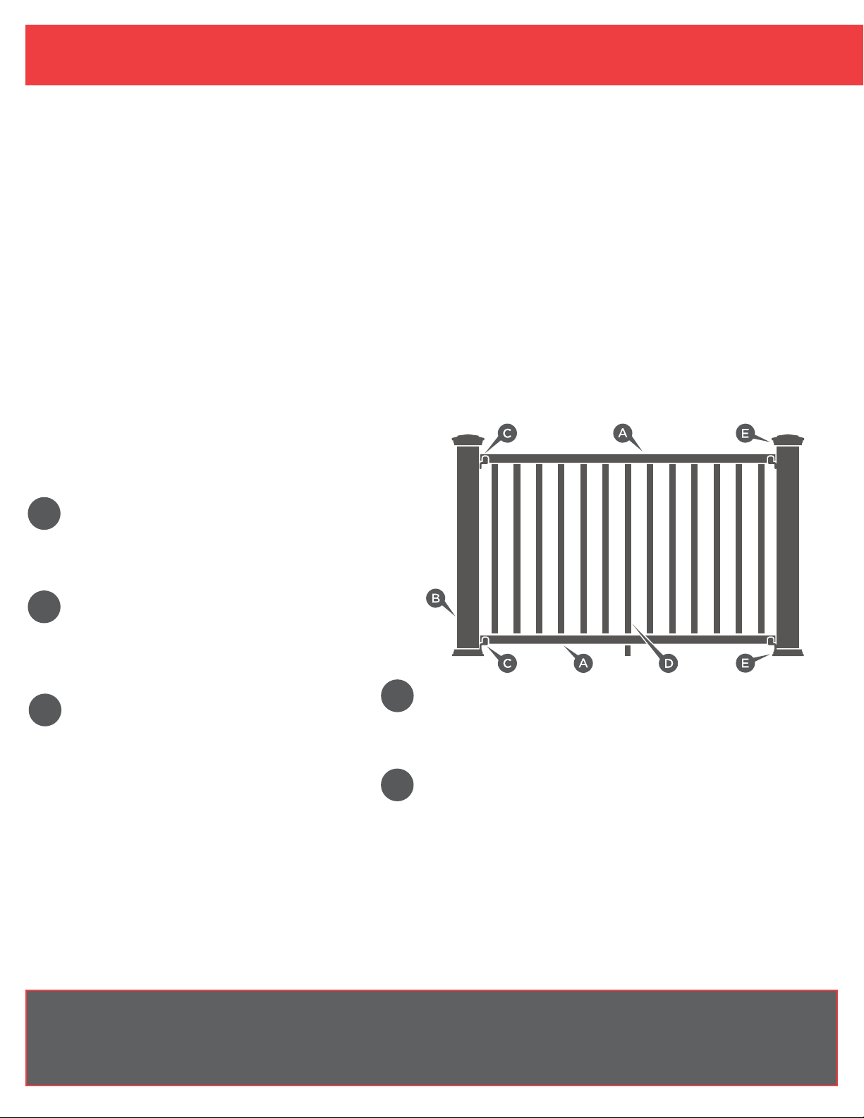
COMPONENTS NEEDED TO INSTALL ONE MARQUEE RAIL SECTION:
KIT SELECTION GUIDE:
Customizing the look of a Marquee Railing System is simple.
Just select at least one of each component kit* listed below
to add style and distinction.
Railing® System. TAMKO® Building Products, Inc. shall not be held liable for improper or unsafe installations. TAMKO
A
B
C
*Note: each component kit is sold separately. Kit types and quantities vary by application.
SUBSTITUTION FOR THESE COMPONENTS IS NOT ALLOWED AS SUBSTITUTING COMPONENTS COULD CAUSE A SAFETY HAZARD.
STRAIGHT/STAIR RAILS
6-Foot or 8-Foot Straight Rail Kit
6-Foot Stair Rail Kit
• Contents: (2) Pre-routed Rails and (1) Crush
Block (no crush block in Stair Rail Kit)
POST KITS
5" x 5" x (48" or 120") Post Sleeve
• Contents: (1) Post Sleeve and Wood Post Spacer
5" x 5" x (38" or 44") Wood Post Mount Kit
5" x 5" x (38" or 44") Concrete Post Mount Kit
• Contents: See page 7-10 for full details.
BRACKETS
Straight Bracket Kit
Stair Bracket Kit
• Contents: (4) Brackets and (1) Rail Screw Pack
Multi-Angle (Left) Bracket Kit
Multi-Angle (Right) Bracket Kit
• Contents: (2) Brackets and (1) Multi-Angle
Screw Pack
D
E
BALUSTERS
36-Inch or 42-Inch Baluster Kits (6-Foot section)
• Contents: (13) Square Balusters
36-Inch or 42-Inch Baluster Kits (8-Foot section)
• Contents: (18) Square Balusters
POST CAPS AND RINGS
5" x 5" Post Cap
5" x 5" Post Ring
MEASURE SPAN BETWEEN POSTS:
Marquee Rail Kits are designed for 6' or 8' lengths from center-to-center of posts. TAMKO recommends verifying the span between posts before
beginning installation.
TOOLS REQUIRED FOR INSTALLATION:
Safety glasses, hearing protection, tape measure, miter saw or hack saw, drill, #2 square drive bit and level. For larger construction projects, a
miter saw and drill are strongly recommended for quicker installation.
TABLE OF CONTENTS:
PREPARATION & TOOL CHECKLIST ....................1
STRAIGHT RAIL INSTALL INSTRUCTIONS ...............2
HORIZONTALLY ANGLED RAIL INSTALL INSTRUCTIONS ...4
STAIR RAIL INSTALL INSTRUCTIONS ...................5
POST MOUNT INSTALLATION WOOD/COMPOSITE ........7
POST MOUNT INSTALLATION CONCRETE ...............8

STRAIGHT RAIL INSTALLATION
MINIMUM 1-5/8"
1-5/8" MINIMUM DISTANCE
FROM FIRST BALUSTER HOLE
TO END OF RAIL
INSTALLATION STEPS:
Fig. 1
1 Install and prepare posts or other mounting surfaces for Marquee
Ensure mounting surfaces are level and plumb. (Fig. 1) TAMKO
Railing® installation.
®
recommends using
Marquee Post Mount systems or wood posts covered with our matching Marquee
Post Sleeve and Marquee Wood Post Spacers.
TO INSTALL MARQUEE POST SLEEVE WITH A NOMINAL 4" X 4" WOOD POST:
1 Slide the first Marquee Wood Post Spacer over the 4" x 4" wood
post and secure in place flush with the deck surface using the
screw provided.
2 Next, slide the second Marquee Wood Post Spacer over the 4" x 4"
wood post and secure in place with the bottom of the Wood Post
Spacer 31" above the deck surface for a 36" rail height, or
37" for a 42" rail height.
3 Finally, place the Marquee Post Ring on the bottom of the Marquee
Post Sleeve and slide post sleeve over the wood post.
IMPORTANT: Use of the Marquee Wood Post Spacer is required for 4" x 4" wood
post applications. Failure to follow these instructions may lead to an unsafely
installed product and will adversely affect coverage under the Limited
Warranty.
To install the Marquee Post Mount Kit, see the full post mount instructions on
pages 7-10.
Fig. 2
2 Measure the length between posts and confirm which Marquee Railing Kit is
required (Fig. 2)
Marquee Railing Kit Lengths:
Nominal Rail Length 6' 8'
Actual Rail Length 67" 91"
3 Lay the bottom rail beside the post sleeves with the pre-routed baluster holes facing
upward and evenly spaced. The rails should extend past the post sleeves on each
side. Mark both ends of the rail where they cross the post sleeve. (Fig. 3a)
IMPORTANT: A minimum of 1-5/8" rail length is required from the end of rail
to first baluster on both ends of the rail.
(Fig. 3a)
Check end spacing and shift
the position of the rail before cutting if required. Ensure that the gap between
posts and balusters will not exceed 4".
When positioned and marked properly cut the bottom rail.
4 Lay the top rail beside the bottom rail with the pre-routed baluster holes aligned.
Mark and cut the top rail to match the bottom rail length and end spacing.
(Fig. 3b)
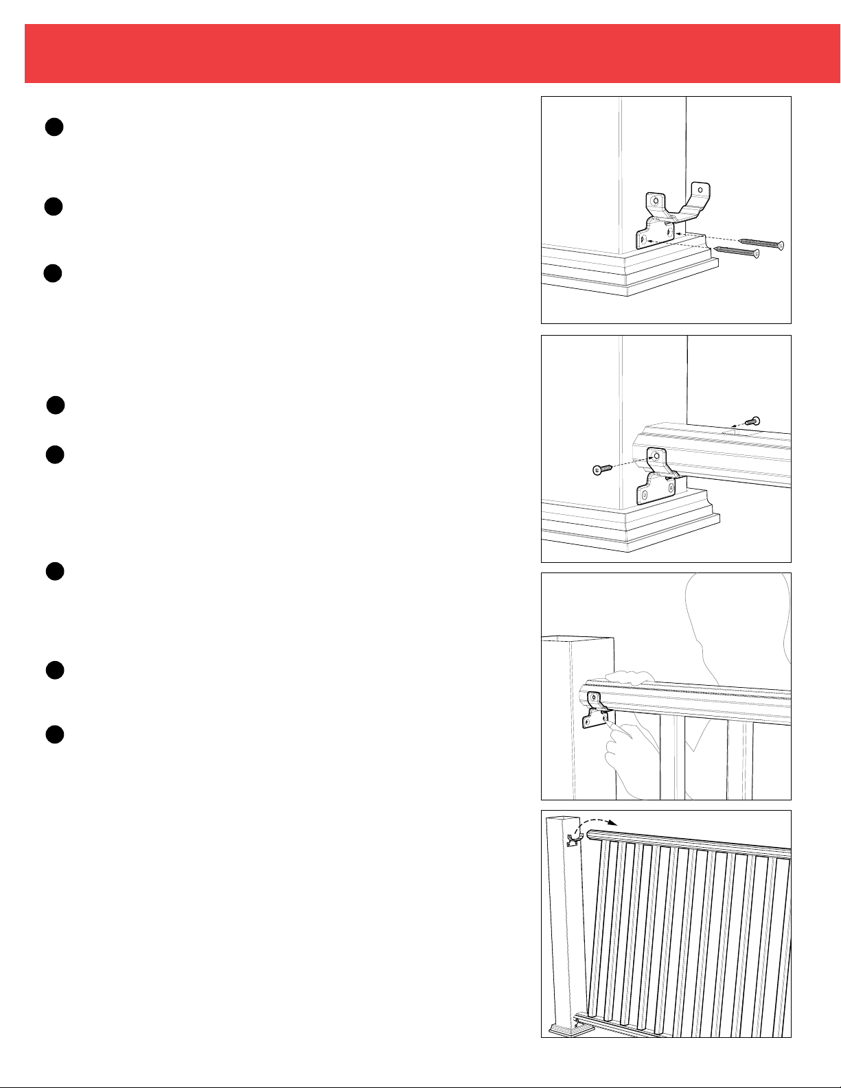
5 To install the bottom rail brackets, place the bottom of the bracket on the top edge
of the Marquee Post Ring and center on post. Secure in place using two of the
screws provided in the Marquee Straight Bracket Kit. Use 2" screws when mounting
to a wood post or the 1-1/4" screws when mounting to Marquee Post Mount.
Repeat on post at opposite end of rail section. (Fig. 4)
Fig. 3a
Fig. 3b
2
STRAIGHT RAIL INSTALLATION (Continued)
Attach the crush block included with the Marquee Rail Kit on the underside of the
6
bottom rail using the screw provided with the crush block. Center the mounting plate
on the deck surface so that it will be in line with the crush block installed on the bottom
rail. Screw the mounting plate to the deck using the supplied screw.
7
Insert bottom rail into the bottom rail brackets, making sure the rail is level. Secure
the bottom rail in place by installing two self-drilling 1" screws provided in the
Marquee Straight Bracket Kit on each side of the brackets. (Fig. 5)
8
Pull down on the bottom portion of the crush block until it sits flush with the deck
surface. Secure in position by installing the supplied retaining screw and colormatched snap cap into the side of the crush block.
Fig. 4
NOTE: Be sure to check with your local building code officials for any bottom
rail clearance or rail height requirements. Improper rail clearance or rail height
could cause a safety hazard.
9
Insert balusters into pre-routed holes on the bottom rail, making sure each one is
fully nested.
10
Align the top rail over the balusters and install one at a time into the pre-routed
holes. Ensure the top rail is fully nested and level with the bottom rail. Position
the top rail brackets on the rail, center the bracket on the post and mark the
bracket locations on each post. When using Multi-angle Brackets, center the
angled rail onto the post. Mark Mutli-angle Bracket location in relation to centered
rail. (Fig. 6)
Remove the brackets from rail. Tilt the rail outward from the post slightly to expose
11
the face of the post. Reposition the top rail brackets at the marked locations on
each post and install with screws provided in the Marquee Straight Bracket Kit. Use
2" screws when mounting to a wood post or the 1-1/4" screws when mounting to
Marquee Post Mount. (Fig. 7) Repeat on post at opposite end of rail section.
Slide the top rail into the top rail brackets and secure in place by installing two self-
12
drilling 1" screws provided in the Marquee Straight Bracket Kit on each side
of the brackets.
13
Attach the post cap using PVC adhesive.
Fig. 5
Fig. 6
Fig. 7
3
 Loading...