

Page 1
I
Page 2

CONTENT
1. Preface-----------------------------------------------------------------------------------------------------------------------------------1
WARNING CLAUSE ---------------------------------------------------------------------------------------------------------------------------1
INTRODUCTION--------------------------------------------------------------------------------------------------------------------------------1
INSTALLATION ---------------------------------------------------------------------------------------------------------------------------------1
SAFETY REGULATION-----------------------------------------------------------------------------------------------------------------------2
2. INSTALLATION & OPERATI ON--------------------------------------------------------------------------------------4
2.1 INSTALLATION OF THE PROTECTIVE COVER--------------------------------------------------------------------------------4
2.2 INSTALLATION OF THE MAINSHAFT---------------------------------------------------------------------------------------------4
2.3 EQUIPPING POWER SOURCE-----------------------------------------------------------------------------------------------------4
3. TECHNICAL PERFORMANCE ----------------------------------------------------------------------------------------4
3.1 PERFORMANCE & CHARACTERISTICS-----------------------------------------------------------------------------------------4
3.2 MAIN TECHNICAL SPECIFICATION-----------------------------------------------------------------------------------------------5
3.3 WORKING PRINCIPLE-----------------------------------------------------------------------------------------------------------------5
4. TRANSPORTA TION & INSTALLATION-------------------------------------------------------------------------5
4.1 TRANSPORTATION---------------------------------------------------------------------------------------------------------------------5
4.2 INSTALLATION -------------------------------------------------------------------------------------------------------------------------6
5. SAFETY PRECAUTIONS --------------------------------------------------------------------------------------------------6
6. CONFIGURATI ON & USE-------------------------------------------------------------------------------------------------7
6.1 CONFIGURATION ------------------------------------------------------------------------------------------------------------------------7
6.2 CONTROL PANEL-------------------------------------------------------------------------------------------------------------------------8
6.3 BASIC OPE RATION-----------------------------------------------------------------------------------------------------------------------8
6.4 VALUE INPUT----------------------------------------------------------------------------------------------------------------------------9
6.5 RESIDUAL UNBALAN CE VALUE DISPLAY---------------------------------------------------------------------------------------10
6.6 BALANCE MODE & ALU BALANCE MODE SELECT---------------------------------------------------------------------------11
6.7 SUPPLEMEN TARY EXPLANATION ------------------------------------------------------------------------------------------------12
7. PROGRAM SETUP------------------------------------------------------------------------------------------------------------12
7.1 PROGRAM FUNCTION INTRODUCTION---------------------------------------------------------------------------------------12
II
Page 3

7.2 ERROR-----------------------------------------------------------------------------------------------------------------------------13
7.3 RESSURE SENSOR INSTALLATION & WIRING-----------------------------------------------------------------------------14
7.4 GEN ERAL TROUBLESHOOTING & SOL UTION-------------------------------------------------------------------------------14
7.5 ACCESSORIES---------------------------------------------------------------------------------------------------------------------------15
8. MAINTENANCE---------------------------------------------------------------------------------------------------------------16
9. OPERATION DETAILED DESCRIPTION---------------------------------------------------------------------18
9.1 HOW TO BALANCE A WHEEL------------------------------------------------------------------------------------------------------18
9.2 PARAMETER SETUP -----------------------------------------------------------------------------------------------------------------19
9.3 CUSTOMER SELF-CALIBRATION-------------------------------------------------------------------------------------------------20
APPENDIX 1----------------------------------------------------------------------------------------------------------------------23
APPENDIX 2----------------------------------------------------------------------------------------------------------------------
24
III
Page 4
1. PREFACE
WARNING
There will be one year of warranty period on the
condition that the machine including the operation
system, tools and accessories are used properly and/or
without damage. During this period, the manufacturer
will repair or replac e the parts returned or the m achine
itself, sustaining the costs but not accepting
responsibility for normal wear and tear, incorrect use or
transportation, or fail ure to carr y out maintenance. T he
manufacturer will not inform the customer about any
improvements to the produ cts or the upgrading of the
production line.
INTRODUCTION
The purpose of this manual is to provide the owner and
operator of this machine with a set of safe and practical
instructions for the use and maintenance of the whe el
balancer.
If such instructions are c arefully followed, the m achine
will offer you the levels of efficiency and duration.
The following paragraphs define the levels of danger
regarding the machine.
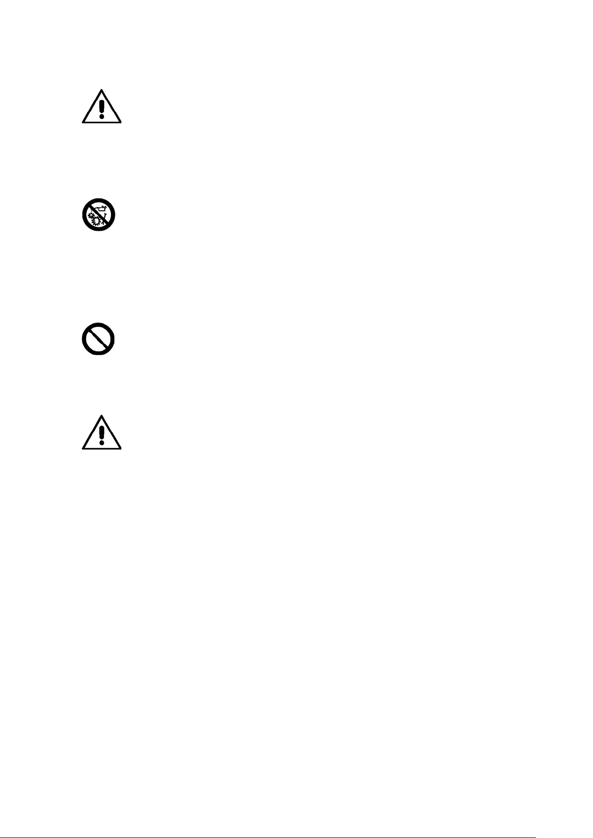
DANGER: Refers to immediate danger with the risk of
serious injury or death.
ATTENTION: Dangers or unsafe procedures that can
cause minor injuries or damage to property.
Read these instructions carefully before using the
machine. Keep this manual and the illustrated materials
supplied with the equ ipment in a folder near t he place
of operation so as to allow the machine operators to
consult the documentation at any time.
The manual is only to be considered valid for the
machine serial number and model stated on the
attached nameplate.
The instructions and information described in this
manual must always be complied with: the operator will
be held responsible for any operation not specially
described and authorized in this manual.
Some of the illustrat ions c ontained in this booklet have
been taken from pictures of prototypes: standard
production machines may differ slightly in certain
respects. These instructions are for the attention of
personnel with basic m echanical s kills. W e have therefore condensed the d escriptions of each operation by
omitting detailed instructions regarding, for example,
how to loosen or tighten the fixing devices. Do not
attempt to perform operations unless properly qualified
or with suitable experience. If necessary, please
contact an authorized Service Centre for assistance.
INSTALLATION
WARNING: Dangers or unsafe procedures that can
cause serious injury or death.
Take the utmost care when unpacking, assembling,
lifting and setting up the machine as indicated below.
1
Page 5
Failure to observe thes e instructions can damage the
machine and compromise the operator's safety.
Remove the original pack ing m ater ials after posit ionin g
them as indicated on the packaging.
All regulations in forc e concerning safety at work must
be complied with when choosing the installation
position.
In particular, the machine must only be installed and
operated in protect ed environments where there is no
risk of exposure to dripping.
IMPORTANT: for the correct and safe operation of the
machine, the lighting level in the place of use should be
at least 300 lux.
Environmental operating conditions must comply with
the following requirements:
- Relative hum idity ranging from 30% to 80% (without
condensation);
- Temperatures ranging from 0° to +50°C.
The floor must be strong enough to support a load
equal to the weight of the equipment plus the maximum
load allowed.
warnings can cause serious injuries to the operator or
other persons.
Do not operate the machine until you have read and
understood all the danger/warning notices in this
manual.
The correct use of this machine requires a qualified and
authorized operator. This operator must be able to
understand the m anufacturer's written instructions, be
suitably trained and be familiar with the safety
procedures and regulat ions . O per ators ar e f orbidd en t o
use the machine under the influence of alcohol or drugs
that could affect his/her physical and mental capacity.
The following conditions are essential:
- r ead and understand the inform ation and instructio ns
described in this manual;
- have a thorough knowledge of the features and
characteristics of the machine;
- keep unauthorized perso ns well clear of the working
area;
- make sure that the machine has been installed in
compliance with all r elevant standards and regulations
in force;
- make sure that all machine operators are suitably
trained, that they are capable of using the machine
correctly and safely and that they are adequately
supervised during work ;
- do not touch power lines or the inside of electric
motors or any other electrical equipment before making
sure that they have been powered off;
- r ead this booklet carefully and learn how to use the
machine correctly and safely;
- Always keep th is user m anual in a place where it c an
be readily consulted and do not fail to refer to it.
The machine must not be operated in potentially
explosive atmospheres.
SAFETY REGULATIONS
Failure to comply with the instructions and danger
Do not remove or deface the DANGER, CAUTION,
WARNING or INSTRUCTION decals. Replace any
missing or illegible dec als. If any decals have become
detached or damaged, it is possible to obtain them from
your nearest reseller.
-Observe the unified industrial accident prevention
regulations relating to high voltages and rotating
machinery whenever the machine is in use or being
2
Page 6
serviced.
- Any unauthorized changes or modifications made to
the machine automatically release the manufacturer
from any liability in the case of damage or accidents
resulting from such changes or modifications.
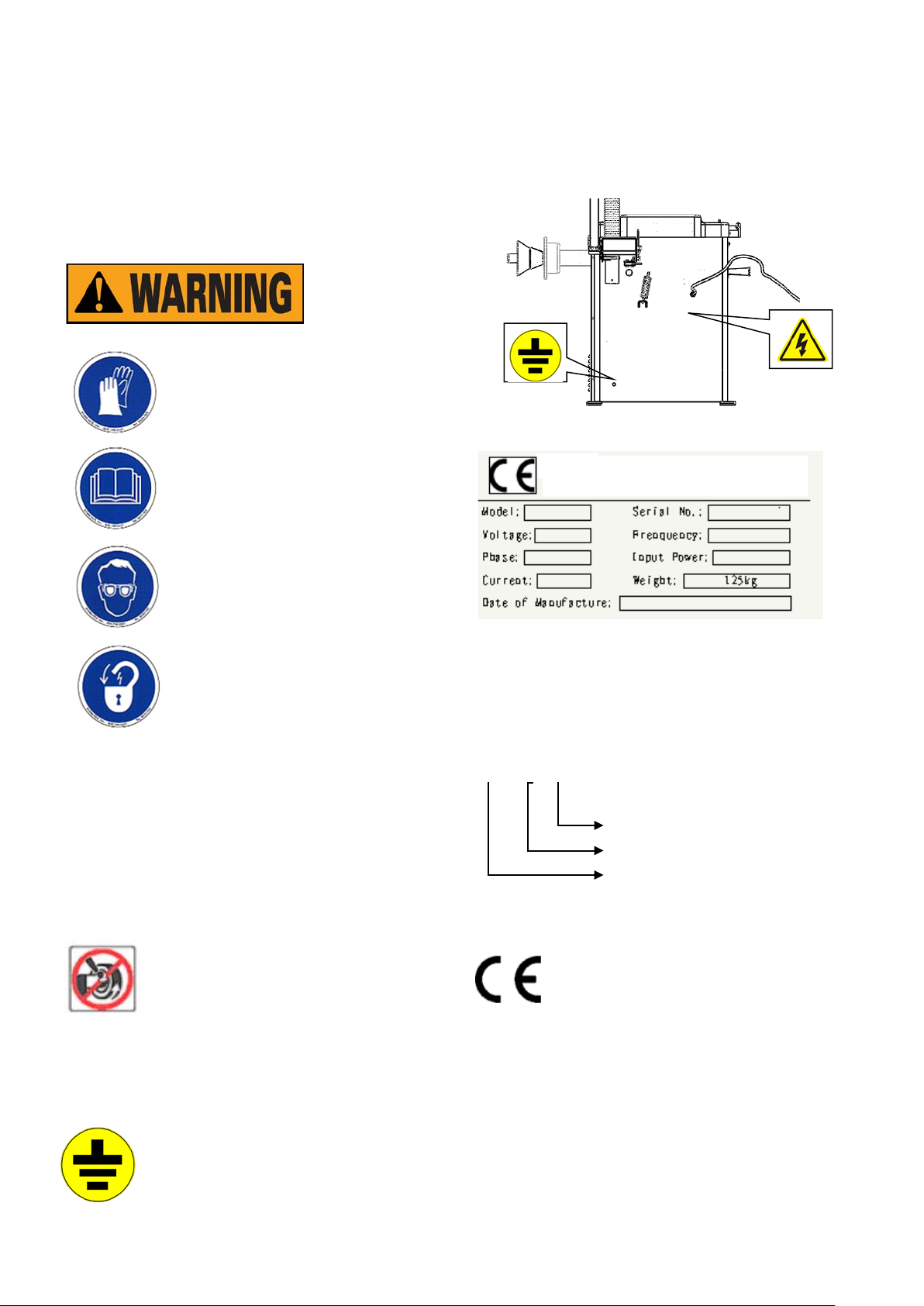
WEAR PROTECTIVE GLOVE
REA D OPE R ATION MANUAL
WEAR PROTECTIVE GLASSES
POWER OFF THE ELEC T RIC AL
SOURCE OF THE MACHINE
DURI NG M AI NTANCE
Meaning of the decals (including the one
indicating caution)
Lightning symbol:This decal, positioned on the back of
the machine, indicates where to insert the power supply
cable and warns the user to pay attention to his safety.
Warning for rotating machine part
This decal, positioned next to the balancing shaft,
reminds the user that this is a rotating part and is
therefore dangerous and should not be touched with
the hands. The arrow indicates the rotation direction.
Grounding symbol: This decal, positioned
on the rear left side of the machine,
indicates where to connect the ground wire.
DECAL LOC ATION DIAGRA M
Nameplate
Note: The following information coming from the
nameplate
The nameplate is stuck in the center to the top on the
rear of the mac hine. T he m eaning of each par t is i n t h e
following:
CB 9XX B
With hood
Model
Computerized dynamic wheel
balancer
B. CE certificate
This mark indicates that this model of
machine has got the CE certificate
C、Series No The first 3numbers is the abbreviate of the
model. The middle 4 is th e manufacture date and the
last 4 is company product series number.
D、What on the cross l ine is the nam e and addr ess of
the company and u nder the cr oss line n ot includes the
above explained but the rated electrical parameters,
3
Page 7
such as voltage、frequency、power、phase number & full
load current, and the weight and manufacture date of
the machine.
If the B has noted in the model of the machine, it means
the machine with the protection cover. It means without
the equipment of the protection cover if without the note
of B.
2 INST A LLATION AND OPERATION
Before installation and us e of the wheel balancer, you
should carefully read this installation and operation
manual. And keep this m anual in hand for r eference at
any time. Y ou should be sure that all the operators have
read this manual to guarantee the most perfect
functions of the machine and meanwhile the safety.
2.1 PROTECTIVE HOOD INSTALLATION:
: shown in page 26~27
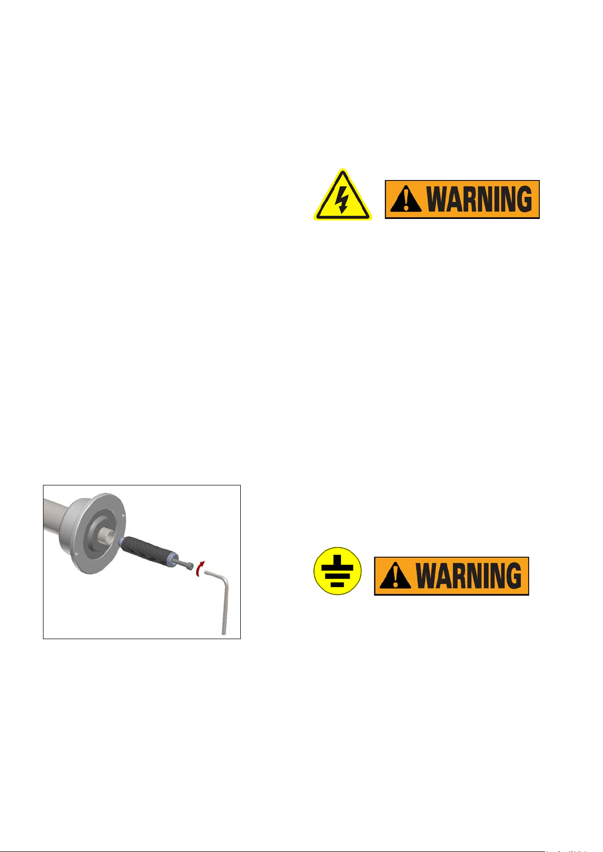
2.2 MAIN SHAFT INSTALLATION
MAINSHAFT INSTALLATION:Before installation, use
the ethyl alcohol and compressed air to clean up the
center hole of the shaft and c onnect part. Use spann er
and screw to fix the thread shaft on the balance shaft
(Fig2)
parameter marked on the nameplate of the machine.
The wiring of the machine m ust have the f use and the
perfect ground protection. And install the electrical
Leakage automatic controls switch in the power source.
And recom mend the application of the stabili zer if the
voltage of installation site is unstable.
Any electrical connect in th e workshop is only done b y
the qualified technical staffs and it should meet the
enforced regulation.
Any electrical connect must be according to the
following:
• Power on the data plate on the machine;
• Voltage decrease cannot exceed 4% of the rated
voltage on the data plate when full load (10% when
start)
-Operators must:
• Install the plug;
• install 30ma circuit breaker;
• install power cable fuse;
• provide with effective workshop electrical connec t to
ground;
- prevent the auth ori zed o p er atio n and p ul l out the p lu g
to prolong the working life when not use the machine.
- If the m ac hine direc t l y co nnec te d to the power so urc e
through the power boar d not the plug, we should use
the qualified staffs to operate.
Fig2
2.3 ELECTRICAL CONNECTION & EARTHING
According to the label on the connection between
power cable and body, the power cable connect
socket must be grounded w ith the rel iabl e eart h w ire.
All the electrical devices installation must be done by
the qualified staff. Before installation, please check
If the power system is comply with the technical
Perfect ground is necessary for the correct operation.
Do not connect the machi ne with air pipe, water pipe,
telephone line and the other unsuitable obj ec ts
3. TECHNICAL FEATURES
3.1 FEATURES:
-adopts quality computer with the feature of high
intelligence and high stable
-mechanical main shaft adopts high prec ision bear ing
4
Page 8
istance from
driven, wear-resistant, low noise
-press stop key to realize the emergency stop
-full automatic dynamic/static balance check
-balance 3 ALU rim and 1 motorcycle tire
-self-calibration and full automatic trouble diagnosis
3.2MAIN TECHNICAL SPECIFICATION
- rated voltage 220V/110V( selectable) 50/60HZ 、
380V/50HZ/1P
-power 250W
-speed 7S(if the weight of the wheel is about 20Kg)
-accuracy ±1g
-noise ≤69dB
-rim diameter 10″~24″
-maximum wheel weight 65kg
-rim width 1.5~20″
-max wheel diameter 44inch
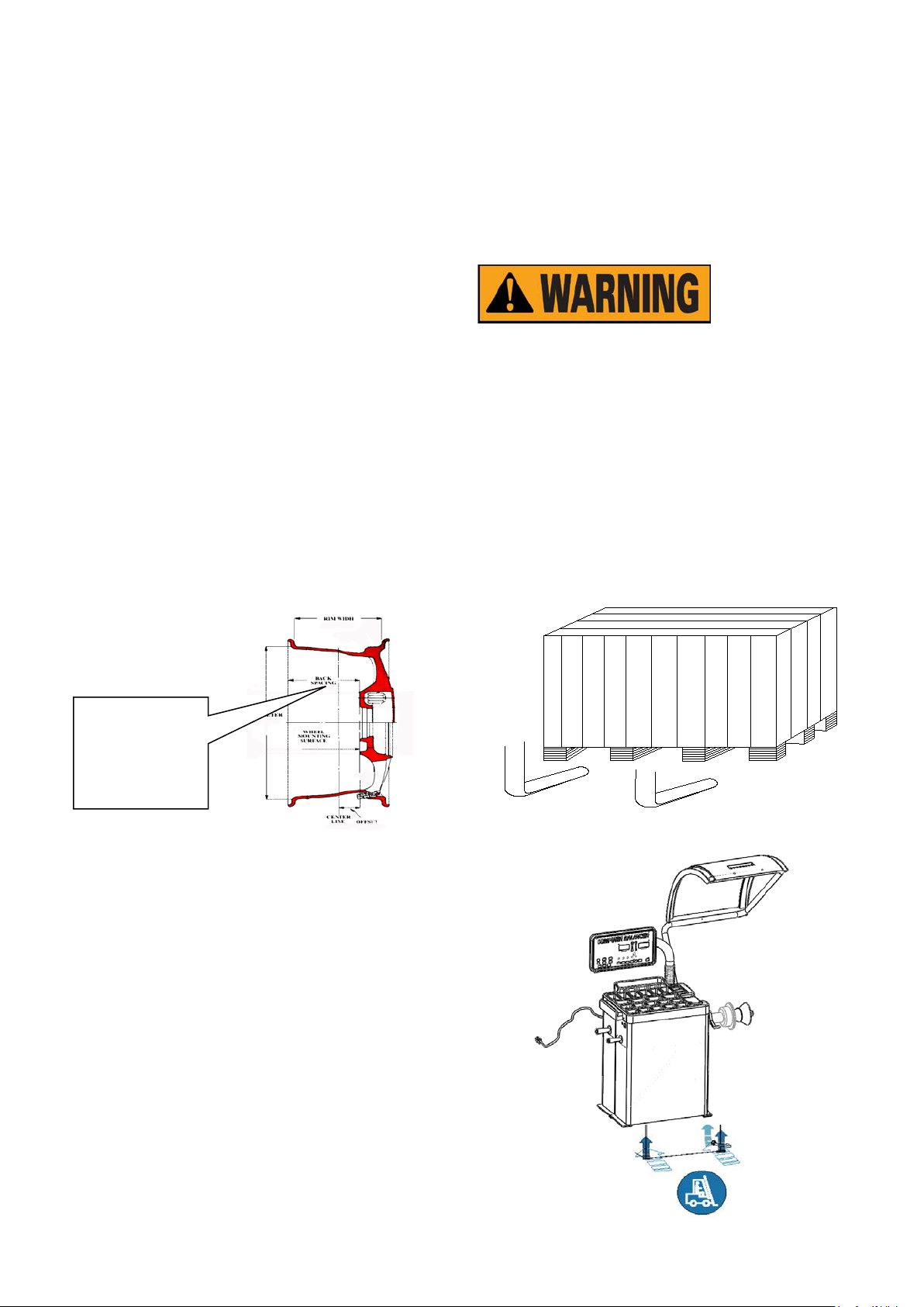
Special instruction:
For the outreach of the main shaft is limited, so there i s
some limit to the distance from flange disk to the
outside edge of the tire should less than 170mm as
shown in the figure. O n this c ondition, you can oper ate
correctly.
D
flange disk to the
outside edge of the
tire
3
.3Work principal
Balancing sensor tests the unba lance signal and send
it to the terminal of the microprocessor via A/D
converter. Processor will calculate the unbalance va lue
through synthesized analysis to the unbalance signal
and angle signal of the main shaft.
4. INSTALLATION & TRANSPORTATION
4.1 TRANSPORTATION
-Place, carry and st ore the machine according to the
indication of the label on the package carton.
- Store environment: RH20%-95% temperature
-10℃-+60℃
-When transport and use t he m achine, do n ot p ull the
rotation shaft, or it will cause the permanent damage
Do not lift the machine at any other position.
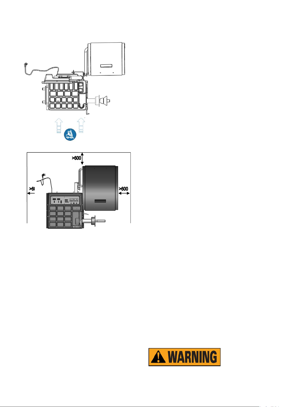
4.1.1After being sure that the package of your machine
is perfect, you can carry the wheel balancer to the
installation site.(Fig3). The choice of the installation
should comply with the following requirements. The
ambient temperature is 0℃-50℃ and the RH ≤85%. And
the installation site as shown in Fig4
FIG3
5
Page 9
4.1.2 Remove the upper cover of the package carton
and check and confirm the wheel balanc er, spare parts
and documents you purchased according to the
packing list. If you have any question, please contact
with the dealer.
Package materials such as plastic, PBV, nail, screw,
timber and carton must be placed into a scrap bin to
treat according to the local regulati on.
4.2 INSTALLATION
Fig 4
the sunlight for long time and the moisture.
5. SAFETY AND PREVENTION
5.1.1 Before operation, please confirm that you have
read the entire warning label and the instruction manual.
Not according with the s afety instr uction can c ause the
injuries to the operators & bystanders.
5.1.2 Keep your hands and the other parts of your body
from the location with the potential danger. Before
starting the machine, you must check it there existing
the damaged part. If any break or damage, the machine
will not be used.
5.1.3In emergency situation, if the tire not fixed, you
should press “STOP” to stop the rotation of the wheels.
Adopts high strength protective cover to prevent the tire
from flying in any direction and can only fall on the
ground to protect the safety of the operators.
5.1.4 Before balanc ing, operators should ch eck all the
tires and wheels to find the possible faults. Do not
balance the tires and wheels with fault.
5.1.5 Do not exceed the load capability of the wheel
balancer and do not attempt to balance the wheel
bigger than the designed dimension.
5.1.6 Wear suitable clothing such as suitable safe ty suit
such as glove, glasses and working suit. Not wear
necktie, long hair, loose clothing. T he operat ors shou ld
stand beside the machine when operation the machine.
Keep from the unauthorized personnel.
5.1.7 Before balancing, you must confirm the
installation of the wheel suitable. Before rotation, be
sure the nut turn 4 turns around the thre ad shaft and
firmly locked on the main shaft.
Remove the connect bolt. And carry down the wheel
balancer to place it on the flat and solid floor. We
should store it indoor to avoid i t from being expose d to
GENERAL CONDITIONS OF USE
6
Page 10
The wheel balancers descr ibed in this m anual mus t be
2 5 1 4 8 6 7
9
10
11
12
13
used exclusively to meas ure the exten t and pos ition of
car wheel unbalances, within the limits specified in the
technical data section . Furthermore, models eq uipped
with motors must be provided with a suitable guard.
The machine must be installed properly, operated
correctly and serviced regularly in order to prevent
accidents and injuries.
Any use other than
those described in this manual is to be considered
improper and unreasonable.
Do not start the
machine without the wheel lock ing equipm ent .
Protective hood
plays the role of prevention and safety.
Do not clean or wash the wheels mounted on the
machine with compressed air or jets of water.
Get to know your machine. The best way to prevent
accidents and obtain top performance from the
machine is to ensur e that all operators know ho w the
machine works.
6. CONFIGURATI ON & USE
6.1CONFIGURATION
Learn the function and location of all the controls.
Carefully check that all controls on the machine are
working properly.
7
Page 11
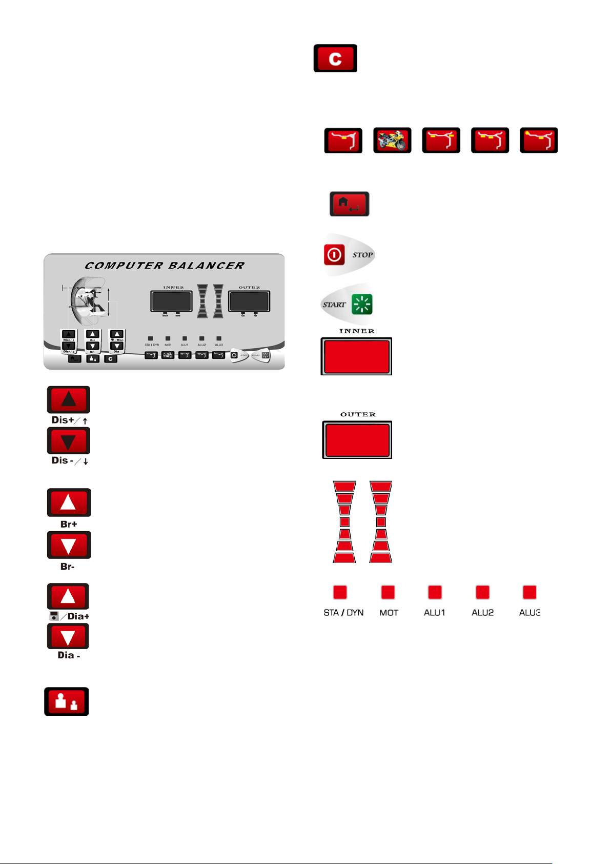
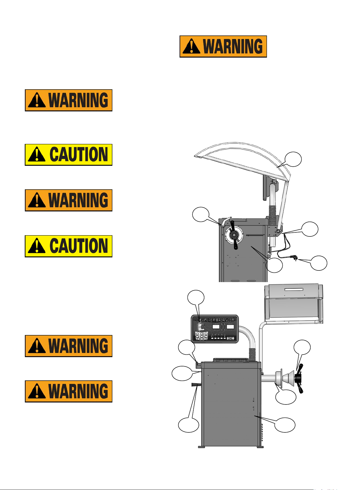
Fig 5
1- Power &plug 2- Side Panel
3- Return Spring 4- main switch
5- Scale 6- control panel
7- Weight Tray 8- Hood
9- Quick Nut 10- Balance Shaft
11- Body 12- power switch
13. Cone Storage Handle
6.2 DISPLAY PANEL & CONTROL PANEL
In the s tate of parameter input, it is the
1.
distance from wheel to balancer input
key .You can change the Br se t val ue of the
window by press the up/down key.
2
. Br value input key you can change the
Br set value of the window by press the
up/down key.
3. In the state of parameter input, it is the
diameter of the rim input key. You can
change the D set value of the window
by press the up/down key.
5. Unit conversion key can convert the unit of the
unbalance value and size.
6. Balancing mode selection key。
7.
parameter of the tire display
tire parameter display
Function key & confirm key
8. Emergency stop key
9. Start key
10. Inner unbalance value and
11. Outside unbalance value and
12. Unbalance position lamp.
13. Balancing modes display lamp
4. High accuracy balance key: When the
display displays [00], press this key the
display will display the unbalance value less
than 5g.
6.3 BASIC OPERATION
6.3.1 Switch on the m ain switch on the left side of the
machine , the display will display
[888]-[708][Uer]-[2.140] and then[ 0]-[ 0](it will display
[0.00]-[0.00] in ounce state)
8
Page 12
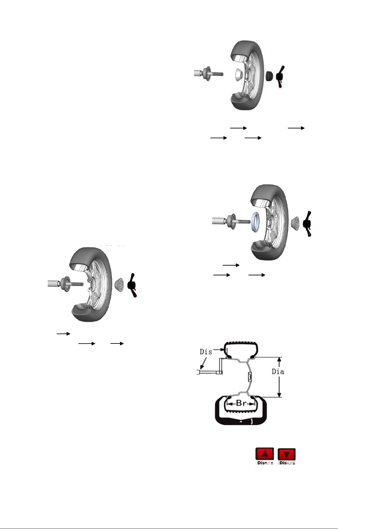
6.3.2 MOUNT WHEEL
Preparation before test:C hec k and clean the dust and
mud and if there ar e f oreig n bodies , suc h as m etal an d
stone, clipped on the surface of the tire. And also check
the air pressure of the tire is according with the
specified value. Check if there are deformation on t he
rim positioning surface and installation hole.
Check if there are any for eign bodies in the tire. Take
off the original weight.
The installation methods of the wheel : Positive
positioning, negative positioning & flange disk when
handling the middle and big sizes of tires. You can
select the methods according to the different
conditions.
6.3.2.1 SMALL CAR WHEEL POSITIVE POSITION
Positive positionin g is the nor m al method. I t is f eatur ed
with simple and quick operation. It is m ainly suitable to
the common steel rim and aluminum alloy rim with
small deformation.
Main shaft lower spring suitable cone
wheel bowl quick nut
6.3.2.3 FLANGE DISK POSITIONING(OPTIONAL)
Suitable to the big tire assemble
Main shaft flange disk(fixed on the main shaft)
wheel cone quick nut
Main shaft wheel(direction of the rim installation
surface is inside) cone quick nut
6.3.2.2
When the deformation of the outside of the wheel,
adopt this method to positioning to grantee the
accurate positioning of the steel rim inner hole and
main shaft. It is suitable to the steel rim, especially the
thick ALU
NOTE: T he choic e on the cone should be adapte d
to the rim center hole a nd pay attent ion to its direction.
Or it will cause the inaccurate measurement.
6.4 INPUT VALUE
6.4.1 Input DIS
Pull the scale to the inner position to add the weight
and press the key
value into the displa y. At this m oment, the display will
(Distance)
to input the DI
9
Page 13
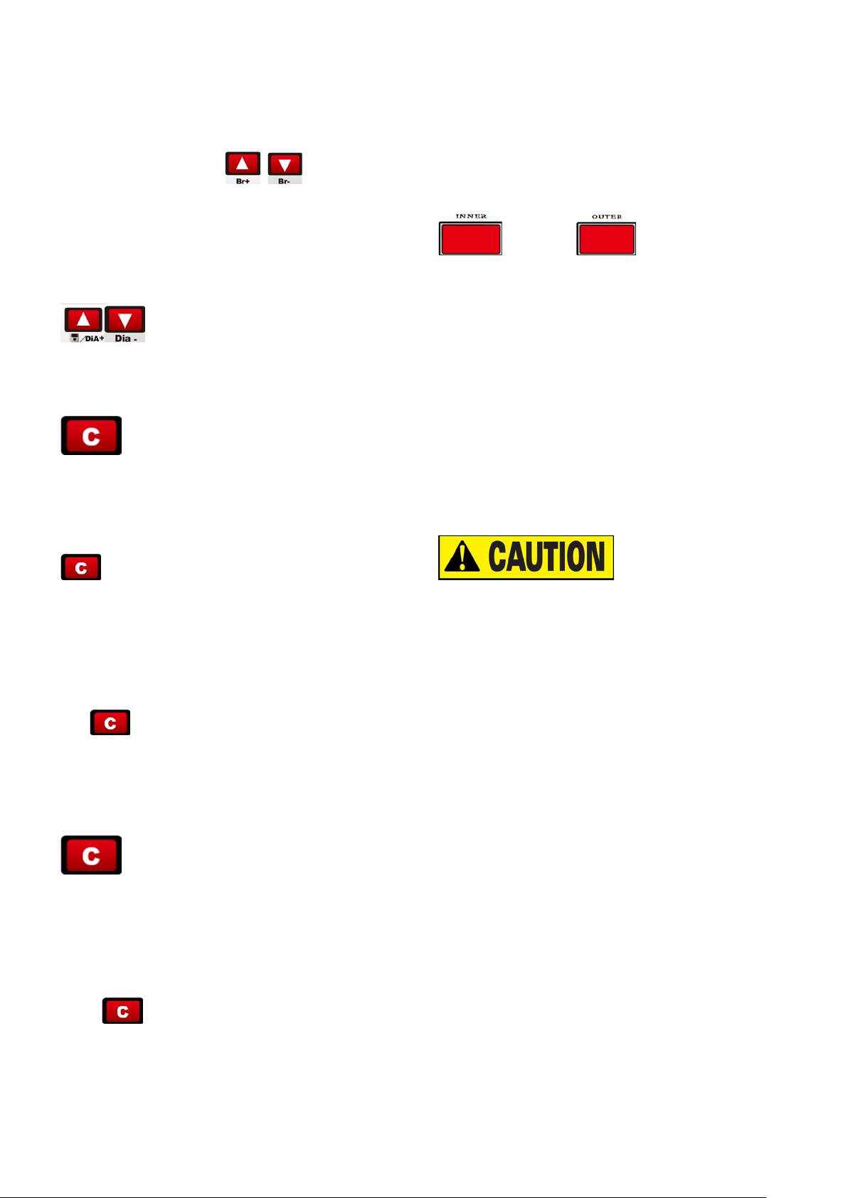
display[DIS]:[XXX],And the default system is mm.
6.4.2 Input Br (RIM Breadth) Value
Use the Br measurem ent caliper to meas ure the Br of
the rim, press the key
to input the Br
value into the displa y. At this m oment, the display will
display [Br. ]:[XXX]. and the default system is inch.
6.4.3 Input the DiA(Diameter)Tire Diameter Value
After confirming the rim diameter, press the key
to input the rim diameter into the display.
At this moment, t he display will disp lay [Dia ]:[XXX].
and the default system is mm.
6.4.4 UNIT CONVERSION:
①The unit convers ion of the Br of the rim from inch to
mm:
Normally, the display of Br should be in inch. When you
need the unit of the d ispla y to be mm , you can use t he
automatically stops. The machine can also start by
lowering down the prot ecti ve hoo d which c an be s et b y
the program.
6.4.6 DISPLAY UNBALANCE VALUE
When the spin ends, the d isplay will display the inner
and outer unbalance value of the
rim. Use your hand to pull the wheel. When all the
positioning lamps light inside and outside light, the
weight adding position will be indic ated .
6.4.7Rotate the wheel, when the left side positioning
lamp all light, at this moment, the highest position is the
inner unbalance position and when the right side
positioning lamp all light, at this moment, the highest
position is the outer unbalance position.
6.4.8 Add the correspo nding weight at the unbalance
point and start test again until the balance of the tire.
Attention:
k ey to realize the un it conversion from inch to
mm.
②The unit conversion of th e DI A of the rim from inc h to
mm:
Normally, the display of D should be i n inch. W hen you
need the unit of the d isplay to be mm , you can use t he
key
to realize the unit convers ion from inch to
mm.
After unit conversion, the unit of the display values of
rim Br and D value, but when you switch off and then on
the wheel balancer, the unit will be still inch.
③The unit conversion from gram to ounce:
Normally, the unit of the unbalance value is gr am (g). If
you want to mak e the ounce (Oz) to be the unit, you
can execute the g/Oz conversion. The unit of the
displayed unbalance value is gram(g). The way to
realize the unit conversion from gram to ounce is to
1. When start the machine, use hand to pull the
wheel to help it start rotation, es pecially to the relative
bigger tire, to prolong the working life of the motor.
2. Check if there are an y mis takes on the dim ens ion.
Check if the balance methods meet the configur at ion o f
the rim and select the balancer most easily to balance.
3. Check if the quick lock nut tight or not.
4. When the balance ends, remove the tire. Pay
attention to handle it with gentle and avoid knocking the
main shaft.
5. When clipping the weight. Use the hammer to c lip
the weight on the rim without too much force. Do not
knock the main shaft hardly to avoid damaging the
sensor. The position to add th e Weight should be free
from the grease and should be dry.
6.5 RESIDUAL UNBALANCE VALUE DISPLAY
The minimum value of the standard weight is 5g s o if
the weight you use is less than 5 g, t he wh eel balanc er
press
6.4.5 When press the start key,the wheel balancer
starts to run. A few seconds later, the machine
will not displa y the value and o nly displa ys the state of
“00”. When you need to d isplay the res idual unb alance
10
Page 14
3
/4” 3/4” 1/2”
1
/2” 3/4”
1
/2”
1
1
/4”
value, you should press and the display will
immediately display the inside or outside unbalance
value of less than 5g. The maximum residual
unbalance value is 4 g.
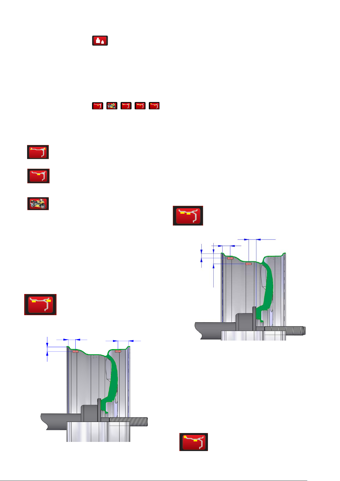
6.6 BALANCE MODE SELECT
Press the corresponding
key to choose the balance mode. If all the lights not
light up, it is the dynamic mode.
DYNAMIC—clip the weight on both sides of
rim(dynamic balance test once start)
STATIC— Stick the weight in centre
MOT—optional for balancing the
ALU1
Dis1=Dis+ 3/4”
Dis2=Dis+Br-3/4”
Dia 1=Dia-1”
Dia2=Dia-1”
ALU2-for ALU rim, hidden weight inside
motorcycle
When balancing motorcycle wheels, you require the
(optional) motorcycle adaptor accessory MJ-II. With the
assistance of the extension scale to measure Di, Br and
Di. Input the measure value into the Di, Br and Di
display window. The input method is similar to the
parameter input of the car.
ALU1- to balance the light aluminum
alloy rim. Adopt clip th e weight on the shoulders of the
rim
ALU2
Dis1=Dis+
Dis2= from 0 point to the outer of the flange disk
-1/2”
Dia1=Dia-1”
Dia2=Dia-2
11
3
/
”
4
1
/
”
2
Page 15
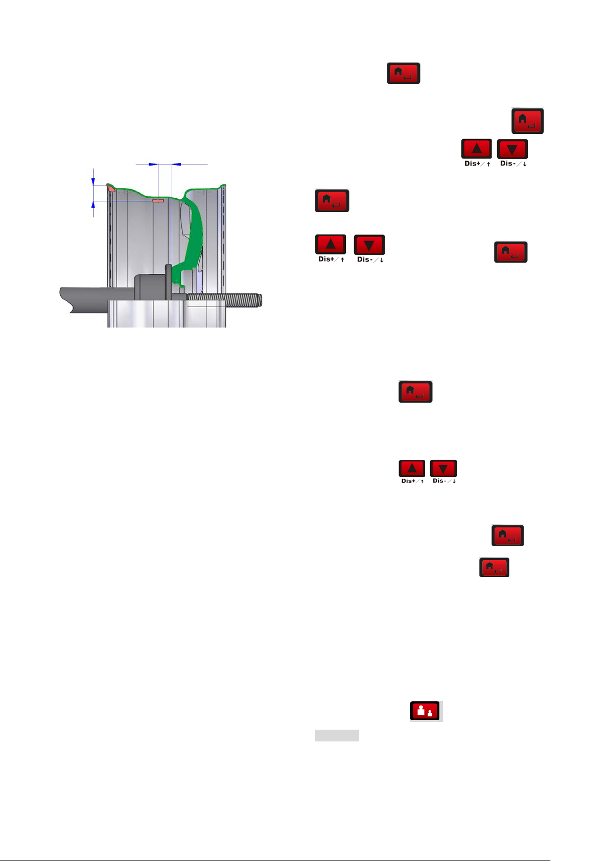
1
/2”
1
ALU3-clip the weight inside and the position to add
weight outside is same to ALU2.
Press program
menu.
-p- (protective cover setup) and then press
key to enter the program s etup
key
1
2
/4”
”
ALU3
Dis1=Dis
Dis2= from 0 point to the outer of the flange disk-
1
/
to confirm the entrance. Select
the on/off of the protective c over function. Then press
key to return to the upper level.
SP(protective cover control function setup) Select
to enter. And press key to
enter. The setup is same to the above.
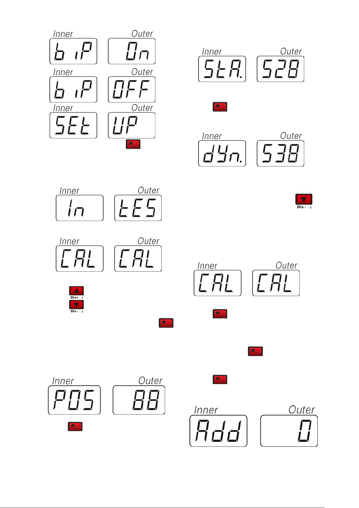
APP(Balance unit s etup) can se tup 1Gr and 5Gr。The
setup is same to the above.
BIP (beeper setup) can setup th e on/off of the beeper.
The setup is same to the above.
SET UP Press
setup.
IN TES (sensor test) to test the photocell and STA/DYN
sensor.
to enter the special functio n
to set
Dia1=Dia
1
/
Dia2=Dia-2
2
”
6.7SUPPLEMENTARY EXPLAINATION:
Once switching on, you will see standard dynamic
balance mode setup b y the computer. When selecting
ALU mode and the conf iguration of the a luminum allo y
rim is similar to the a bove standard ALU 1\ALU2\ALU3,
you can get relative accurate balance effect. If the
section of the tire similar to the one given be the
program, you need do some adjustment on the position
and weight of the weight. G eneral speaking, 1 ~2 times
of adjustment can reach relative satisfactory balance
effect.
7PROGRAM SETUP
7.1 PROGRAM FUNCTION INTRODUCTION
Next menu: Se lect
This function is used when the machine has not been
used for long time or the balancing is not accurate.
Self-calibration pr ogram setup: Press
into the program and then press
and the display wi ll d ispla y ADD -0. Press the s tart k ey
to start the test. After running, the display will display
ADD -100, rotate the tire until all of the unbalance
position lamp light up. Clip a weight of 100g at the 1 2
clock position on the tire. Once again start the machine
to realize the self-calibrat ion of the machine. Ent er the
shortcut method of the self-calibration program and
hold on pressing for 5seconds and enter
“ADD”-“0”.
The above operation step vector diagram is as follows:
12
to enter [CAL] –[CAL].
to enter
to Confirm
Page 16
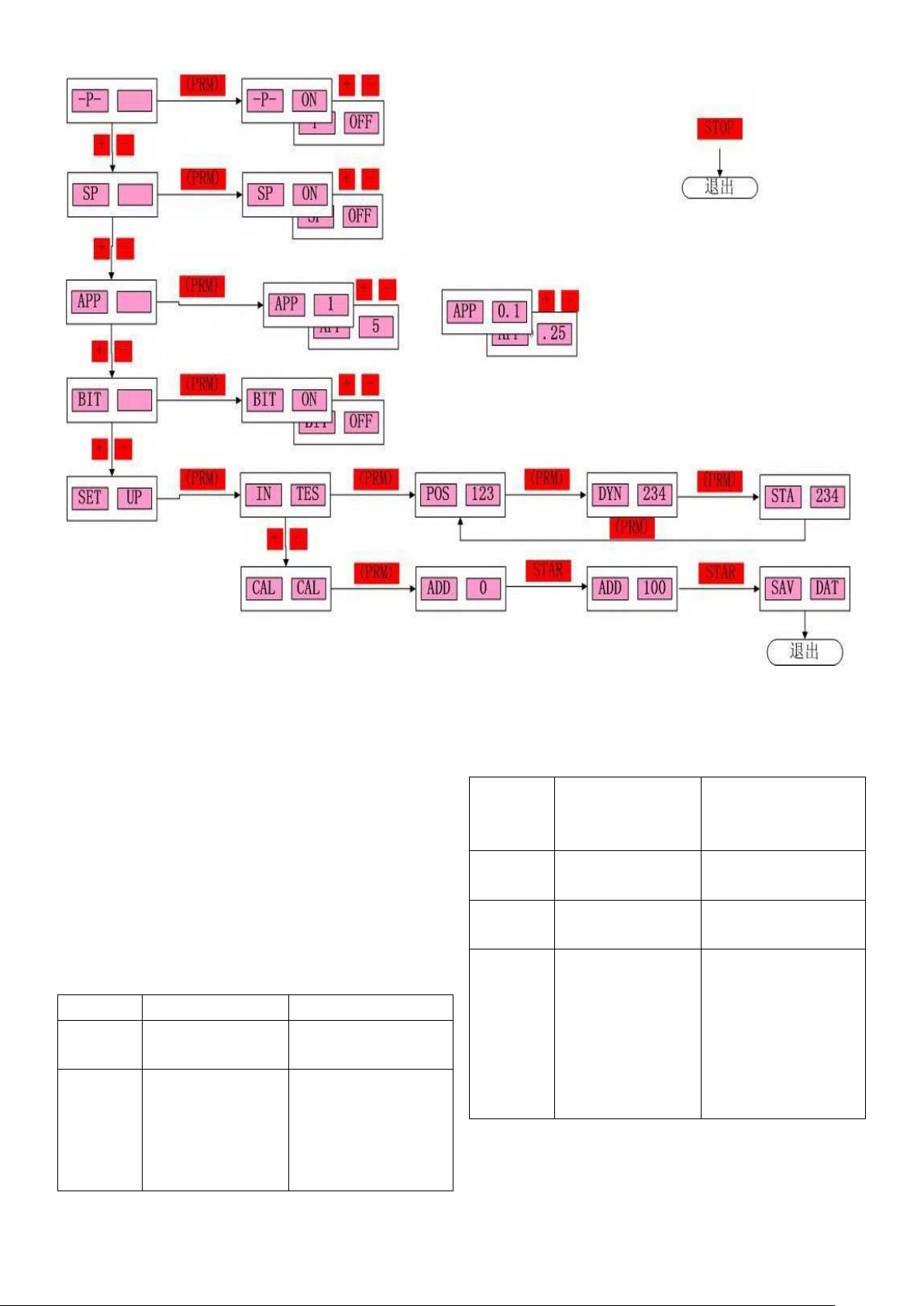
n the
rotation speed not
photocell coupler
Check the motor and
the photocell data
Press the start key or
rise up the protective
If you cannot solute by the above-mentioned method,
please contact with the professional persons.
7.2 ERROR INDICATION
DISPLAY CAUSE SOLUTION
ERR
OPN
ERR
SP
protective cover not
lower down
enough
cannot collect signal
Lower dow
protective cover
belt.
Check if the display of
normal
ERR
OFF
ERR
FAC
ERR
USR
ERR
REU
error of stop
cover.
factory set-up fault Correct factory set-up
customer set-up fault Customer set-up
Reverse rotates is
not correct
Troubleshooting of
power board
Check power cable
connection correct or
not, the wire sequence
of the 3-phase motor
must be correct
If cannot solve as per the above methods, please
contact the professional personnel
13
Page 17
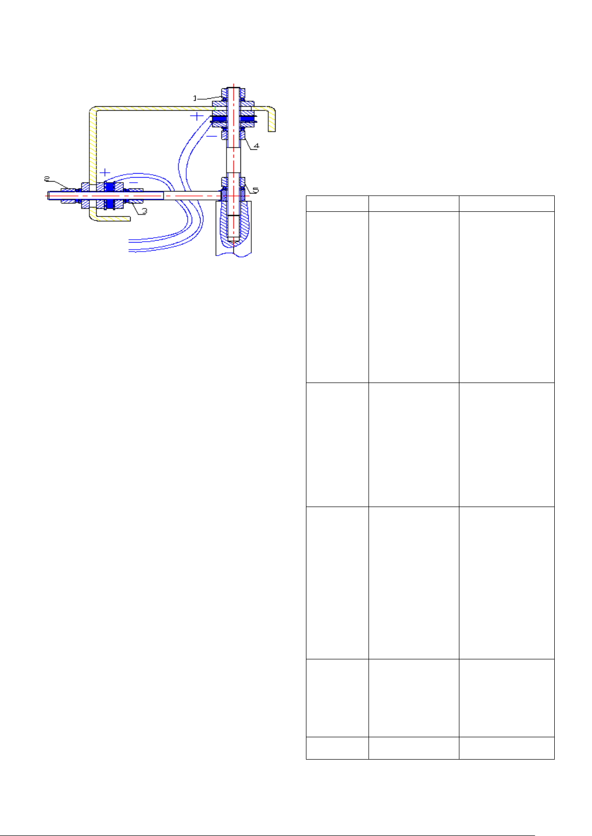
7.3 PRESS SENSOR INSTALLATION AND WIRING
board fault
1. There are
Sometime, the troubl esome of inacc uracy of balanci ng
and position if because the damage of the press sensor.
The method to change the press sensor is shown in the
following:
●Demount the upper cove r and right side panel of the
wheel balancer.
●Remove the nut 1&2, elastic washer, sanding washer
and plain washer.
●Loose the nut 3, 4 and 5 to disassemble each part.
●Change the new s ensor and mount the double hea d
screw and tight the nut 5.
●Use the spanner to tight nut 4 slight ly and then tight
nut3. At this tim e, pay attention that the horizontal an d
vertical sensor sc rew should to perpendicular t o each
other. The end of the screw should fall into the center of
the hole with the gap of at least 1mm.
● Mount the plain washer, sanding washer, elastic
washer and nut1 and 2. It must be completely tight.
Generally speaking, you should fix the nut1 first and
then nut 2.)
●There is the glass glue protective coating on the
pressure sensor.
●Short cut connect of press sensor output cable to
discharge and the n plug the cable disc harged into the
computer board to avoid the high voltage to break down
the computer board.
● Plug the sensor plug according to the original
position.
●Calibrate the balancer once again and mount the
upper cover and side panel.
After change the computer board, p hase sensor or the
press sensor, you must execute t he self-calibration. In
the process to change the computer board, you should
setup the parameter according to the parameter
marked in the m achine or the original boar d. You must
self-calibrate after changing
7.4 GENERAL TROUBLESHOOTING & SOLUTION::
Description Cause Solution
1. Check the
1. Check and
connect the external
power source.
2. Changer the
power board
3. Check the plug
cable
4. Change the
computer board
1. Open the housing
of the machine and
plug in and tight the
contact switch plug.
2. Start the machine
again
1. Plug in and tight
the cable between
the computer board
and power board.
2.Change the power
board 3. Change the
computer board
1. Connect again 2.
Correct the memory
value according to
the manual.
1. Change the
Start the
machine but
not display.
Display is
normal but
the start
button and
input push
button not
working.
Display is
normal but
not braking
after start.
Balance is
not accurate
& difficult to
reach “00”
Each spin,
circuit of 220V is
normal or not.
2. power board
fault
3. The cable
between the power
board and
computer loose
4. computer board
fault
1. contact switch
not good
2. machine
breakdown
1. The cable
between the power
board and
computer lose 2.
power board fault
2. Brake resistor
damage
3. computer
1. sensor lead
connects or contact
no good
2. memory value
lost
14
Page 18
dick not locked.
QUANT
SCALER
THREAD
WEIGHT
1
LARGE CONE
FLANGE DISK
the change
of the value
will not
exceed 5g
Each spin,
the range of
the change
of value will
be 20-90g.
Balance is
not accurate
& difficult to
reach “00”
When
second
mount &
demount,
the error will
exceed 10g.
foreign body on the
rim or the assemble
surface in the rim
center deformation
2. sensor damp
or quick nut not
tightly clamped
3. The external
power voltage or
the air pressure not
enough. The flange
1. There are
foreign bodies on
the wheel or the
unbalance of the
wheel value too big.
2. sensor damage
3. external power
source voltage too
low
1. Sensor damp
or damage
2. Program chore
1. Wheel internal
hole irregular
2. Flange disk
assemble not
properly
wheel
2. Oven,
recalibrate the
sensor.
3. Fix the anchor
bolt.
1. Change the
wheel
2. Check the
sensor and wiring.
3. Check power
source and assemble
stabilizer.
1. Calibrate
again,oven and then
self-calibration or
change
2.Self-calibration
again
1. Change the
wheel 2.Check the
assemble surface
and try again.
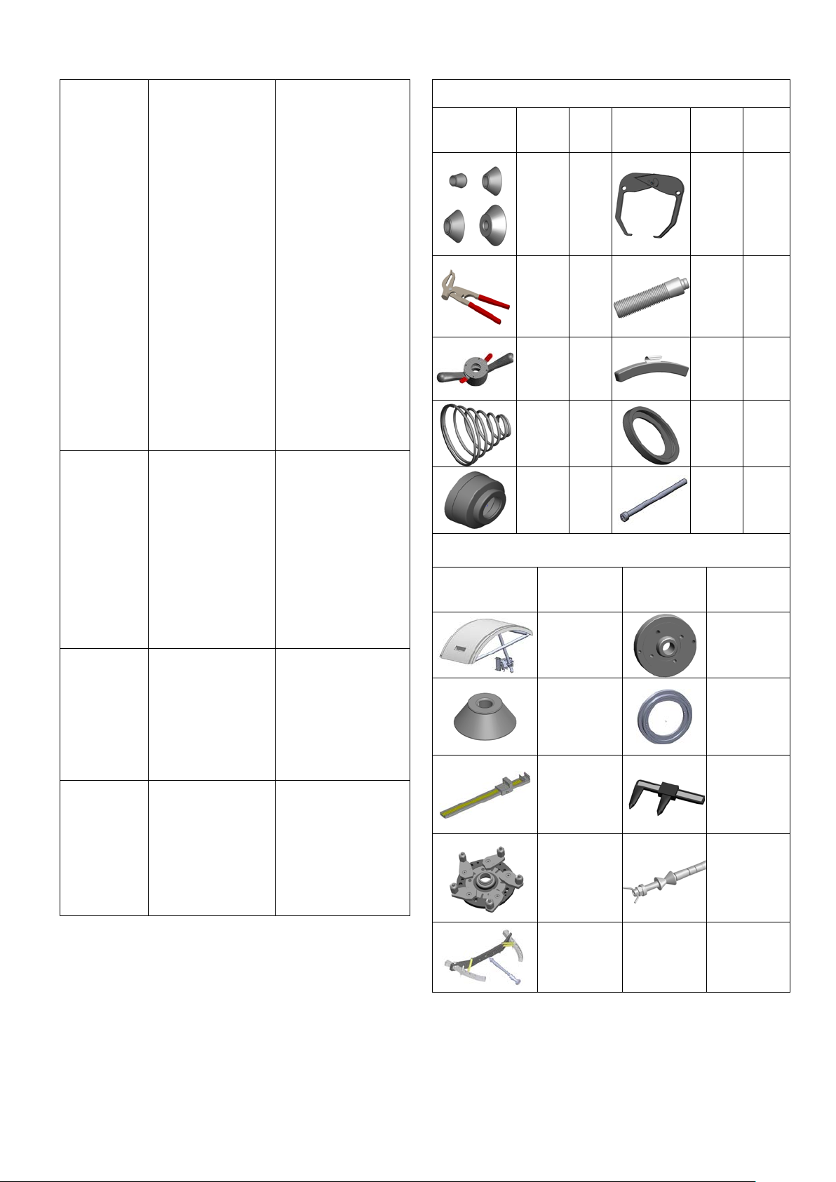
7.5Wheel balancer st andard accessory
STANDARD ACCESSOR Y
ACCESSORY
ACCESSORY
DESCRIP
TION
CONE 1 SET
PLIER
QUICK
SPRING 1PIECE
BOWL
PIECE
1PIEC
NUT
1PIEC
OPTIONAL ACCESSORY
DESCRIPTIU
ON
HOOD
WEIGHT
STICK SCALE
DK-W-1
MJ-I I
ITY
1
E
E
ACCESSORY
ACCESSORY
DESCRIP
TION
BR
SHAFT
BOWL
EDGE
HEXA
BOLT
M10X160
DESCRIPTIU
ON
4-POSITION
ADAPTOR
CENTERLES
S RIM CALIP
MJ-I
QUANTI
TY
1
PIECE
1
PIECE
PIECE
1PIECE
1PIECE
15
Page 19
8. MAINTENANCE
Penetration on the processed
Dropping point, °C, ASTM D 2265
ange of penetration
4 spheres test, impression
WARNING
The manufactur er will not bear an y responsibility
in the event of claims resulting from the use of
non-original spare parts or accessories.
WARNING
Unplug the machine from the socket and make
sure that all moving parts have been lock ed
before performing any adjustment or
maintenance operation.
WARNING
Do not remove or m odif y any part of the machine
(except for service interventions).
CAUTION
Keep the work area clean.
Never use com pressed air and/or jets of water to
remove dirt or residues f rom the machine. Take
all possible measures to prevent dust from
building up or rising during cleaning operations.
Keep the wheel balancer shaft, the securing r ing
nut, the centering cones and flange clean. These
components can be cleaned using a brush
previously dripped in environmentally friendly
solvents. Handle cones and flanges carefully so
as to avoid accidental dropping and subsequent
damage that would affect centering accuracy.
After use, store cones and flanges in a place
Type of thickener
Colour, appearance
item 25°, ASTM D 217,
mm/10
Viscosity oil base, ASTM D 445,
Li-complex
Dark blue
235
280
100
where they are su itably protected from dust a nd
dirt. If necessary, use eth yl alcohol to clean the
display panel. Perform the calibration procedure
at least once every six months.
LUBRICATION
The only rotating parts of the wheel balancer are
the motor and balance shaft. These parts must be
periodically lubricated by the operators. If the
machine is used very frequently, more than
2hours per day, we should annually check the
bearing. And we will check once a year if the
machine is used less than 2hours a day. When
test, do not open up the bearing so you need
insert a screwdriver to t est the noise. Due to the
function of the bearing is to clamp and support
and not suitable to c han ge or r emove the grease.
In addition, the speed of it is not too fast
compared to the m achine so no need to change
the grease. If you note the run of the bearing
abnormal or there is n oise, change the bear ing. If
the customer confirms the bearing is not changed,
you only need change the grease. Disassemble
the bearing and open up the s ealing ring and fill
the XHP103 grease. T hese operations shoul d be
guided by the profession p ersonnel and calibr ate
the machine after changing the grease. If the
change of the grease not correctly, it will
influence the accuracy of the machine. On this
condition, you need to reinstall the sealing ring
and assemble the machine and adjust again.
Technical safety card fo r using grease in the
wheel balancer
Mobilgrease XHP
NLGI degree
cSt @ 40°C
Ch
10
consistency, ASMT D 1831
(established upon the r olling of
the greases), mm/10
0.5
diam., ASTM D 2266, mm
16
Page 20
4 spheres test, welding load,
315
ity of oxidization bomb
4048
Resistance to water spray,
D 1264, loss (weight%), @
79°C
ASTM D 2509, kg
Test Timken OK load, A STM D
45
2509, lb
Stabil
35
method, ASTM D 942, pressure
drop at 100 hours, kPa
Corrosion prevention, ASTM D
Passed
1743
Emcor rust, IP 220, was h away
0
with acid water
Rust protection, IP 220-mod,
0
wash away with distilled water
Corrosion on copper, ASTM D
1A
15
ASTM D 4049, % spray
Wash away with water, ASMT
5
SCRAPPING
If the machine is to be scrapped, separate all
electrical, electronic, plastic and ferrous
components and dis pose of them separately, as
provided for by local regulations in force.
ENVIRONMENT INFORMATION
If the machines ha ve the crossed-out bin symbol
on their data plate
, the following disposal
procedure must be applied to.
This product ma y contain s ubstances that can be
hazardous to the environment and to human
health if it is not disposed of properly.
Electrical and electronic equipment must never
be disposed of in the us ual municipal waste but
must be separately collected for their proper
treatment.
The crossed-out bin symbol
, placed on the
the product mus t be disposed of properly at the
end of its life.
Thus, the hazardous consequences that
non-specific treatments of the substances
contained in these products, or improper use of
parts of them, may have on the environment or on
human health are prevented. Furthermore, this
helps to recover, recycle and re use many of the
materials contained in these products.
Electrical and electronic manufacturers and
distributors set up proper collection and treatment
systems for these products for this purpose.
Contact your local distributor to obtain information
on the collection proc edure s at the en d of the l ife
of your product.
When purchasing this product, your distributor will
also inform you of the poss ibility to return another
end-of-life piece of equipment free of charge as
long as it is of equi valent type an d had the s ame
functions as the purchased product.
Any disposal of the product performed in a
different way from that described above will be
liable to the penalties pro vi ded for b y the natio nal
regulations in force in the country where the
product is disposed of .
Further measures for environmental protection
are recommended: recycling of the internal and
external packaging of the product and proper
disposal of used batteries (only if contained in the
product).
Your help is crucial to reduce the amount of
natural resources used for manufacturing
electrical and electronic eq uipment, minim ize the
use of landfills for product disposal and improve
the quality of life, preventing potentially
hazardous substances f rom being r e lease d i n the
environment.
product and on this pag e, reminds the user that
FIREFIGHTING MEANS TO BE USED
17
Page 21
Consult the following table to choose the most
suitable fire extinguisher.
Dry materials
Water YES
Foam YES
Powder YES*
CO2 YES*
YES* Use only if m ore appropriate extinguishers
are not at hand or when the fire is small.
Flammable liquids
Water NO
Foam YES
Powder YES
CO2 YES
Electrical equipment
Water NO
Foam NO
Powder YES
CO2 YES
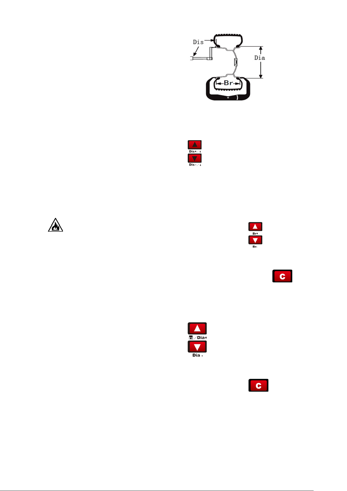
3.1 Pull out the scale of the ba lancer to m easure
the Di value which means the distance from the
insider of the tire to the body. According to
measured reading, the unit of which is cm, pr ess
to adjust the value to make the value
displayed in the right-side window to be the
measured value. But the unit of this displayed
value is mm. eg you should input 55mm if the
measured value is 5.5cm.
3.2 Use the width measurement scale to measure
Warning
This table contains general instructions to be
used as guidelines for users. All the applications
of each type of extinguisher must be obtained
from the relevant manufacturer.
9.DETAILEDMACHINE
OPERATION
9.1 How to balance a tire?
1. Switch on the power source
2. Select the cone according to the tire. Assemble
the tire on the main shaft of the wheel b ala nc er
and firmly lock it.
3. Input the tire parameter.
:
the Bre。you can press
value which is the implied value with the unit of
inch. If you want to convert this value into the
value with the unit of mm, press
realize the conversion between the units.
3.3 Check the D value, which means the diameter
of the rim, marked on the tire. Press
key to adjust the value in the right
window to be the diameter of the rim. You
can also realize the conversion of the unit of the
Dia to be mm by the
to input the Br
to
key.
4. Lower down the protective cover(you can also
press the start key). After the machine start,
rotate and test, it will automatic stops. In the left
/right window, the corresponding values will be
displayed. Rotate the tire, when all the position
18
Page 22
indication lamps light. Pls add the weight
corresponding to the value displayed in the
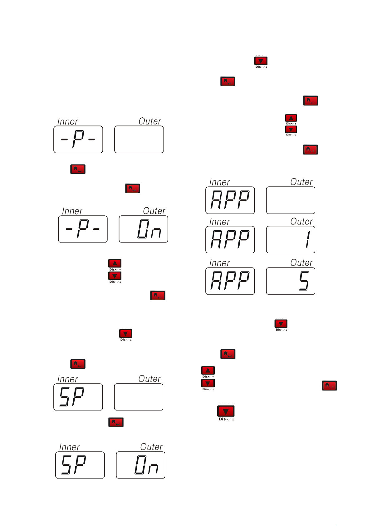
1.3 APP(minimum unbalance setup), In the
window. Once again, start the machine to test.
The window will display the unbalance value. The
upper state, press
balance process will be completed unti l reaching
the balance range you requied.
Press
to enter the setup
9.2 MACHINE PARAMETER SETUP
Select the corresponding unit,Press
confirm the entrance, Select
unbalance unit is 1Gr or 5 Gr. Press
confirm.
Press
to enter program setup menu.
1.1 -p-(hood setup) press
to confirm the
entrance select
to setup the on/off of
the function of the hood. Press
confirm.
to
1.2 –SP-(hood control function setup),In the
BIP (beeper setup) Press
upper condition, press
. The display will
on/off of the deeper.
display as the left figure.
to confirm the entrance.Select
Press
Press
to confirm the entrance.
to enter the APP setup.
key to
to select the
key to
to setup the
Select
to setup the on/off of the hood
function. Press
confirmation.
to confirm after
to setup the on/off of the beeper. Press
to confirm.
Press
19
to enter the sub-level
Page 23
1 “
SET”— “UP” Press to enter the
special function setup program
2 option:“
IN”– “TES”和 “CAL” –“CAL”
installation of the sensor is correct
Press
In the condition of DYN, press the pizeo sensor
9.3 CUSTOMER SELF-CALIBRATION
In the condition of
enter
self-calibration state. We use this when the
machine has not been used for a long time or the
balancing is inaccurate.
key to test static sensor
IN -TES,select to
CAL –CAL,means customer
Select
In the condition of “
enter the condition of test.
In the condition of POS, rotate the tire clockwise,
the value in the right window will increase.
Counterclockwise, decrease.
Press
In the condition of STA, press the pizeo sensor
perpendicular to the m ain shaft, the value in the
right window will change which means the
to display in cycle.
IN”—“TES”,press to
key to test static sensor
Press
This function can be used after inputting tire
parameter.
*hold on pressing
enter this state.
Press to enter and the display will display
“
ADD”-“O”
20
to enter into the program.
for 5seconds to
Page 24
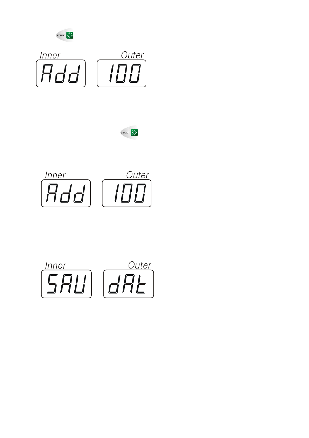
Press to span the machine.
The window will display “
your hand to rotate the tire until all the right side
lamp light up. At this moment clip the weight of
100g at the 12 clock
ADD”-“100”,then Use
position outside of the tire. Press
span the machine. Until the span is over, you
finish the self-calibration
of the machine.
After complete the customer self-calibration, it will
display “
self-calibration is finished.
SAV”-“DAT” Then the customer
to
21
Page 25
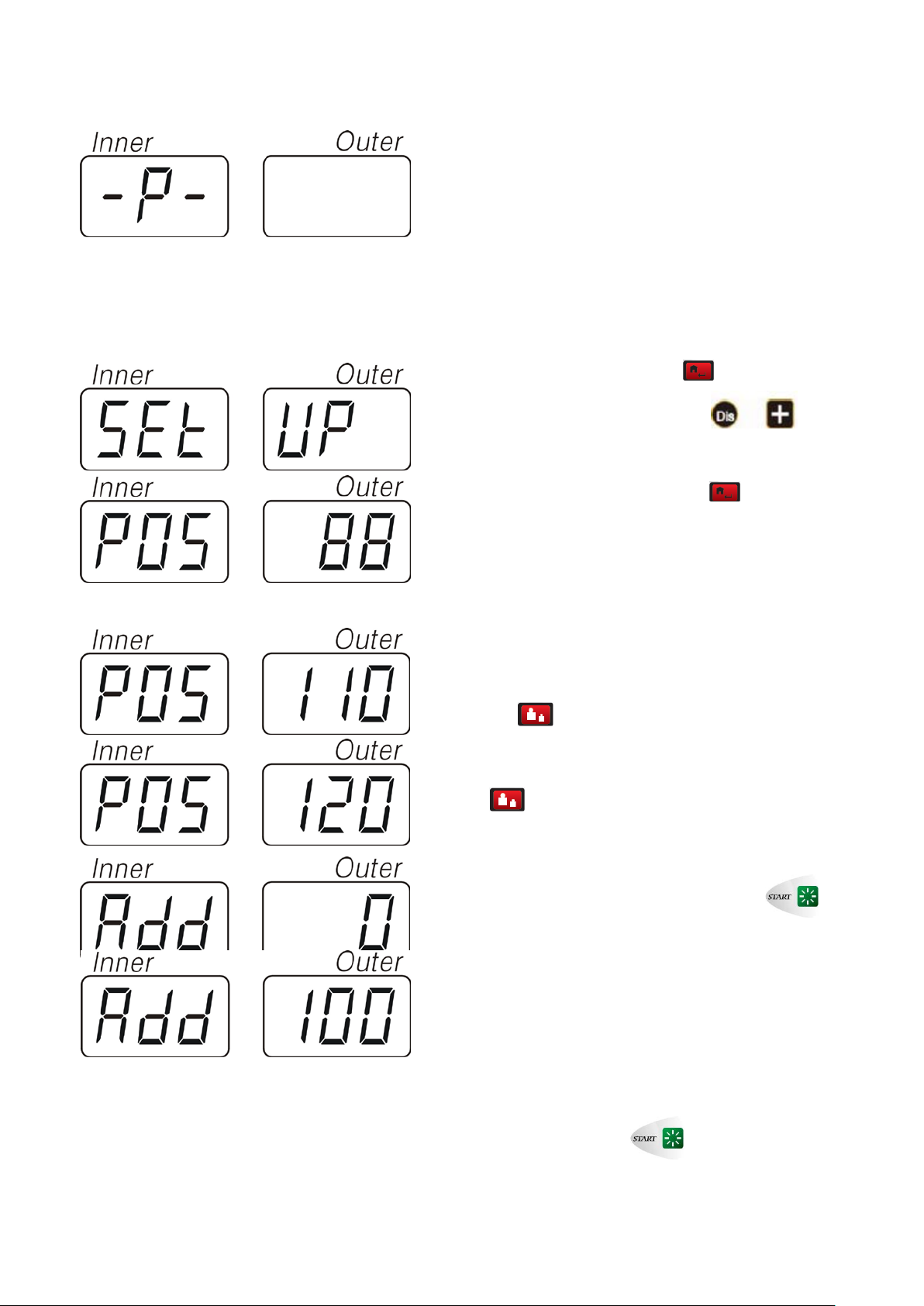
Factory Self-Calibration:
If the customer self-calibration will not be helping to
maintain the machine to have satisfactory balancing
stability, we recommend that you proceed Factory
Self-Calibration procedure. Below you would find the
detailed instruction:
Press “Home button” one time ,and it displays
P ]”, press “DIS + button” one time , and
“[
you will see “[
SET ]-[ UP ]”
Press “Home button” two times
[
POS—XXX], pull the wheel by hand( clock-wise or
anti-clock-wise) slowly.
When it displays [POS]—[110] press ‘Fine button”
one time
until it displays [
time
The screen displays [ADD]-[ 0 ], press to
start rotation o f the machine.
,then continue to pull the whee l sl ow ly
POS]—[120] Press “ Fine button” one
.
, and it dispalys
When machine stops rotation, it displays[ADD]—[100] ,
at this moment, please pull the wheel until the outer
indicating lights are all illuminating, clamp 100g
calibration standard weight on the outside rim at 12
o’clock position. Press
machine.
23
to start rotation of the
Page 26
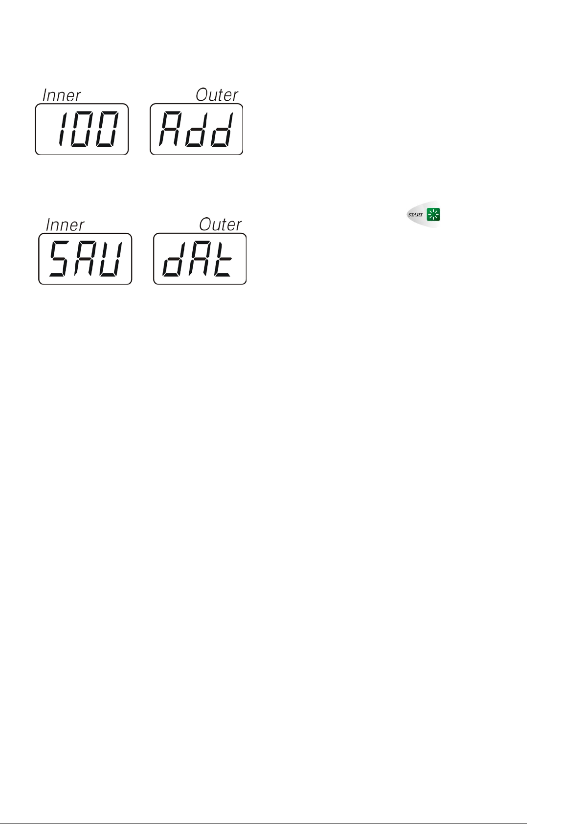
When the machine stops, it displays “100—ADD “, at
this moment please remove that 100g standard weight
from the outside rim edge firstly, then pull the wheel by
hand until the inner indicating lights are all illuminating,
clamp that 100g standard weight on the inside rim at 12
o’clock position, Press to start the rotation
again.
When it stops, you w ill hear 3 times be ep s indication and
the Factory Self-Calibrat io n is over.
24
Page 27
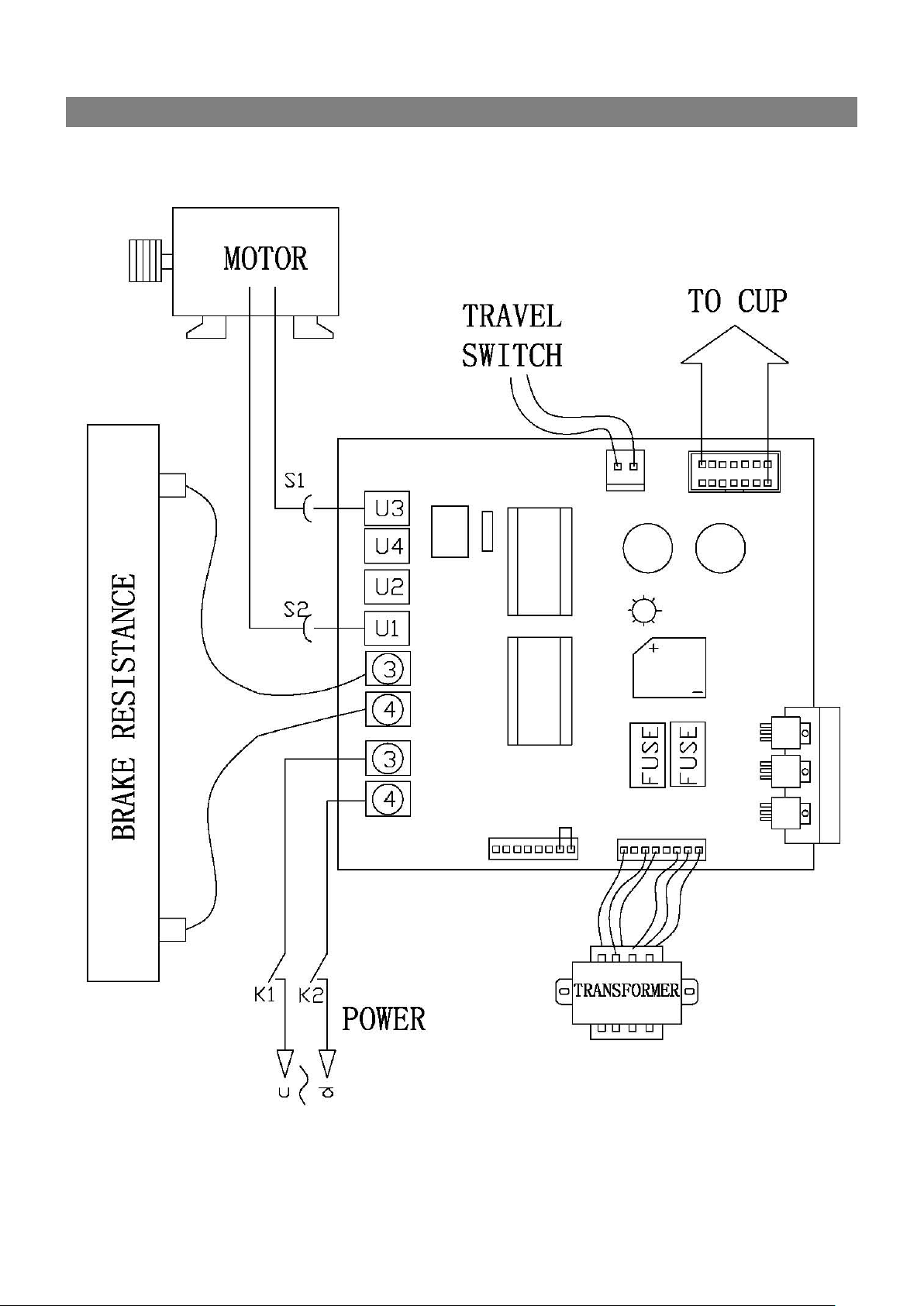
APPENDIX 1 POWER DOARD LAYOUT
25
Page 28
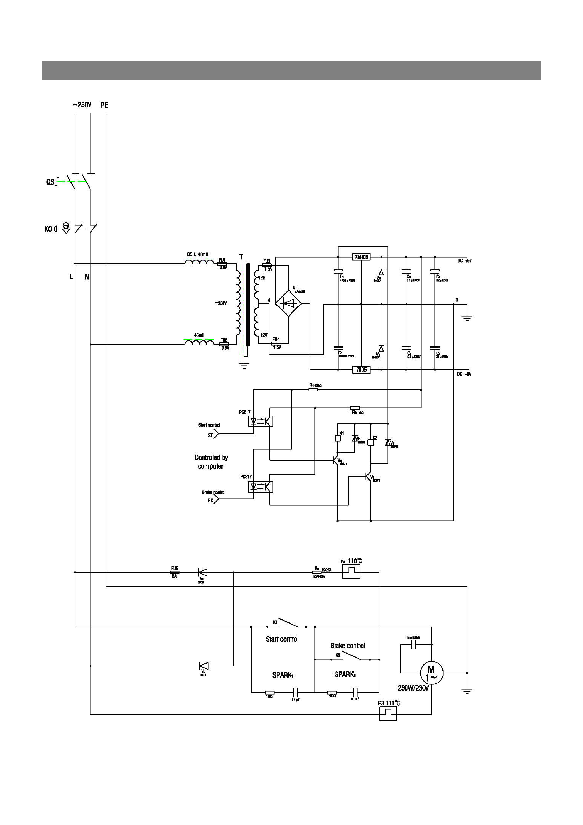
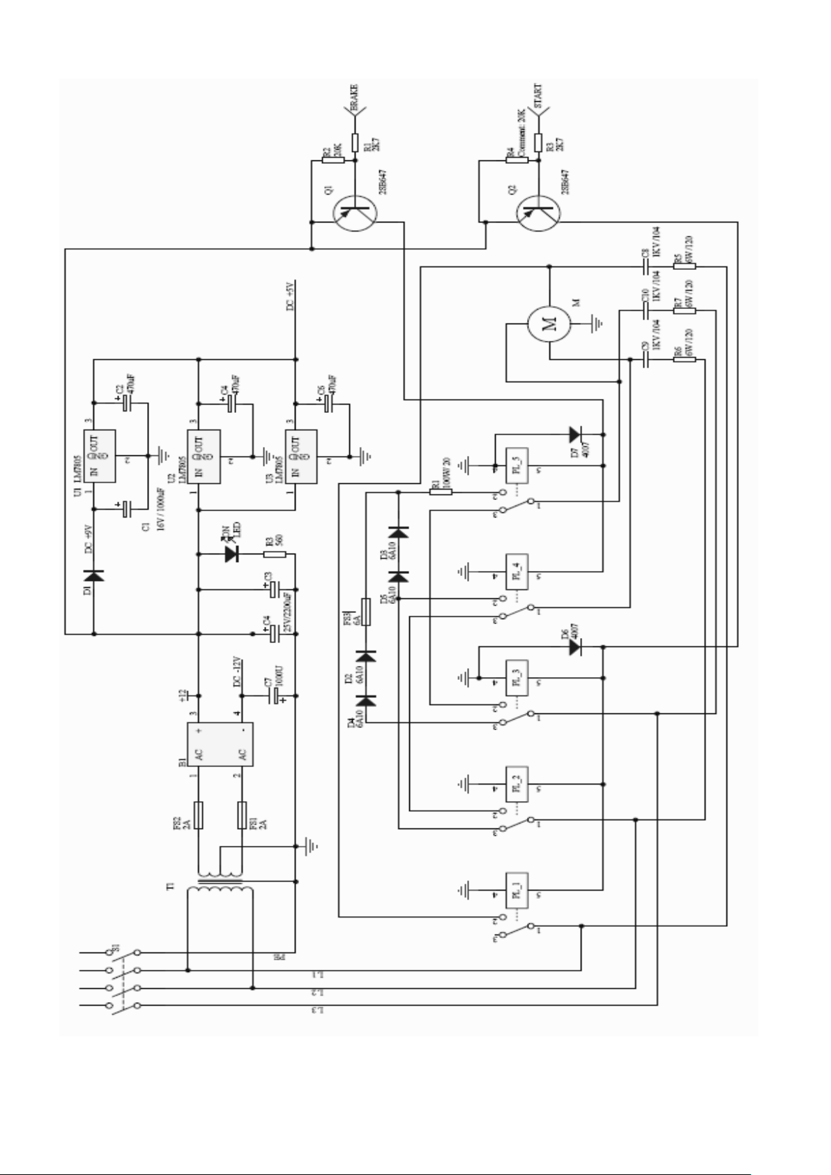
APPENDIX 2 CIRCUIT SCHEME
26
Page 29
27
Page 30
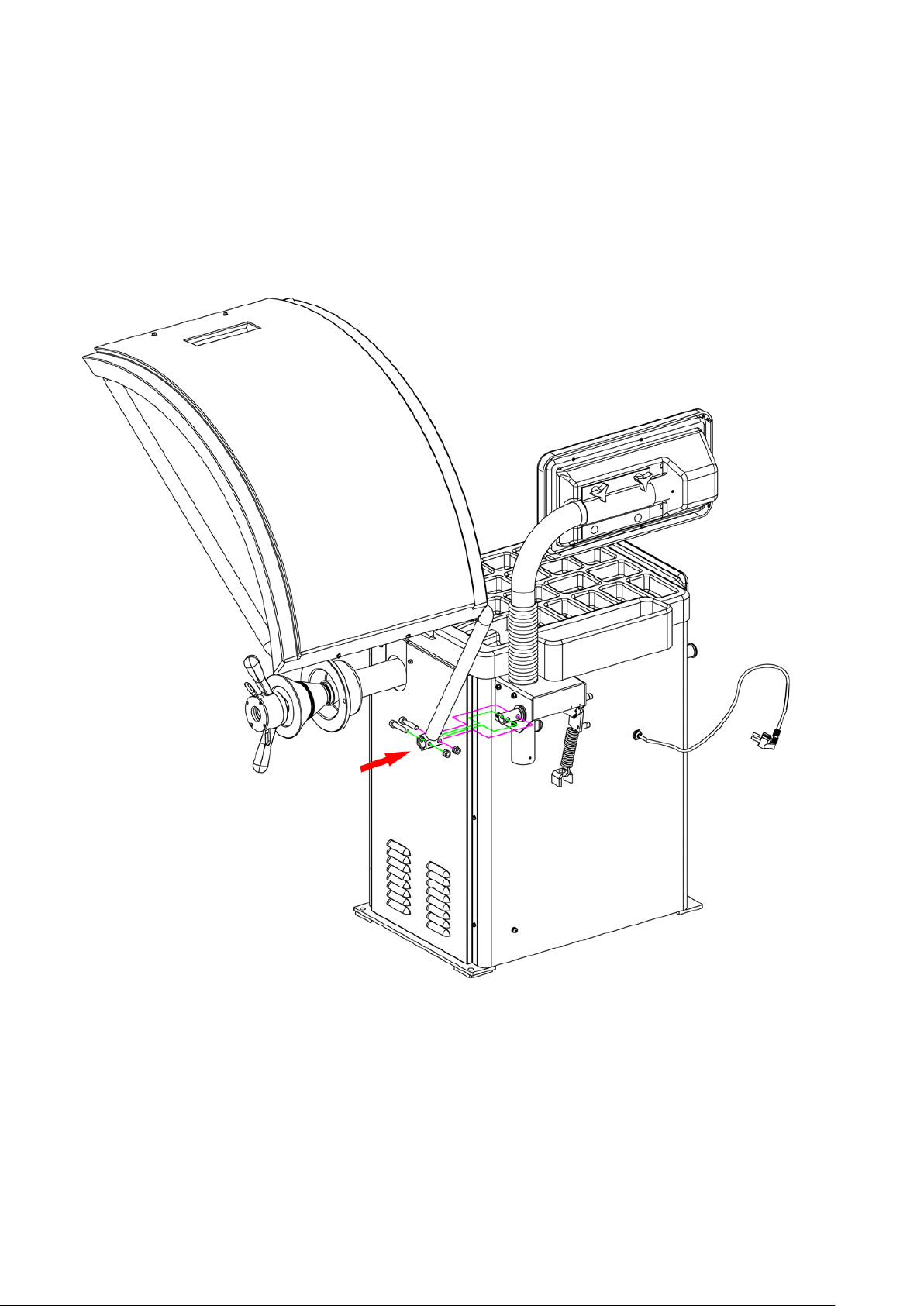
Appendix
Protective cover installation I
28
Page 31
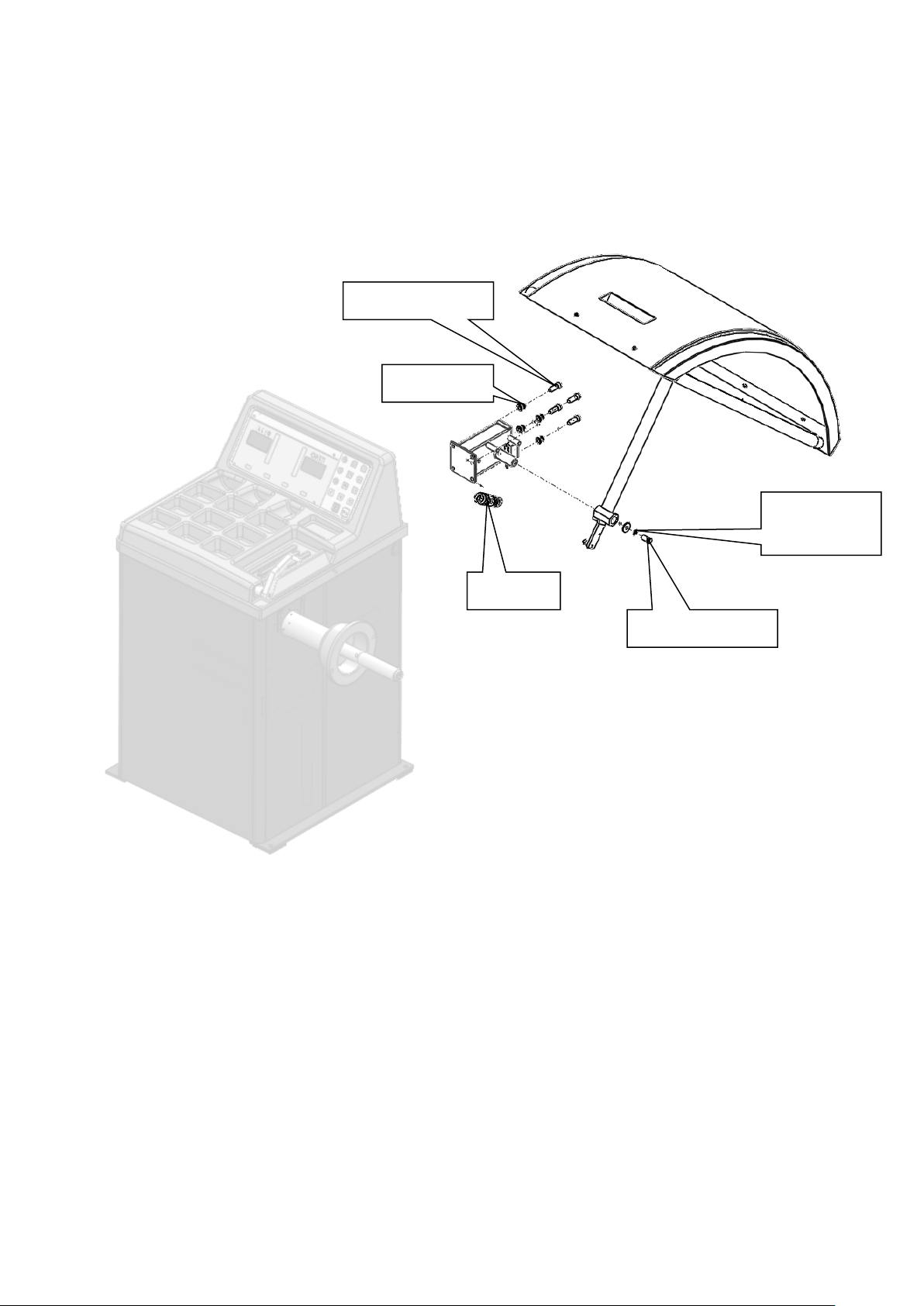
Appendix
Protective cover installation II
Hex. Screw M10X30
Flat washer 10
Spring washer
Spring
Screw M10X20
10
The manufacturer has the right to modify the products without notification to the buyer in advance
29
 Loading...