

Page 1

TB15 3
FR
Hydraulic Excavator
Serial No.
¡
TB153FR: 15820004~
¡
TB180FR: 17830004~
Book No. AL5E001
OPERA TOR’S MANUAL
TB18 0
FR
W ARNING
Read and understand these instructions.
Failure to do so can cause injury or death.
Page 2
SAFETY ALERT SYMBOL
This symbol means Attention! Be Alert! Your Safety Is Involved.
The message that follows the symbol contains important information
about safety .
Read and understand the message to avoid personal injury or death.
■ It is the owner or employer’s responsibility to fully instruct each operator in the
proper and safe operation of all equipment. All persons using this machine should
thoroughly familiarize themselves with the following sections.
■ All operators must be instructed on the proper functions of the excavator before
running the machine.
■ Learn and practice correct use of the machine controls in a safe, clear area before
operating this machine on a job site.
CAUTION
Improper operation, inspection and maintenance of this
machine can cause injury or death.
Read and understand this manual before performing any
operation, inspection or maintenance on this machine.
■ Always store this manual near at hand preferably on the machine itself. If it should be lost
or damaged, immediately order a new one from your Takeuchi dealer.
When transferring ownership of this machine, be sure to provide this manual to the next
owner.
■ Takeuchi supplies machines complying to the local regulations and standards of the country
of export. If your machine has been purchased in another country or from a person or
company of another country , it may not have the safety devices or safety standards required
for use in your country . Should you have any question about whether your machine complies
with the regulations and standards of your country, contact a Takeuchi dealer.
■ Please note that the contents and diagrams included in this manual may not match your
machine exactly.
Page 3

It is your responsibility to observe all pertinent laws and regulations and to follow
the manufacturer’s instructions on machine operation, inspection and maintenance.
Virtually all accidents occur as the result of a failure to observe basic safety rules and
precautions. An accident can often be avoided by recognizing potentially hazardous
situations beforehand. Read and understand all of the safety messages which explain
how to prevent these accidents from occurring. Do not operate the machine until you are
sure that you have gained a proper understanding of its operation, inspection and
maintenance.
■ SlGNAL WORDS
Safety messages appearing in this manual and on machine decals are identified by the
words “DANGER”, “WARNING” and “CAUTION”. These signal words mean the following:
DANGER WARNING CAUTION
The word “DANGER”
indicates an imminently
hazardous situation
which, if not avoided,
can result in serious
injury or death.
IMPORT ANT: The word “IMPORTANT” is used to alert against operators and
maintenance personnel about situations which can result in possible damage to the
machine and its components.
The word “WARNING”
indicates a potentially
hazardous situation
which, if not avoided,
could result in serious
injury or death.
The word “CAUTlON”
indicates a potentially
hazardous situation
which, if not avoided,
may result in minor or
moderate injury.
It is impossible to foresee every possible circumstance that might involve a potential hazard.
The warnings in this manual or on the machine can not cover all possible contingencies. Y ou
must exercise all due care and follow normal safety procedures when operating the machine
so as to ensure that no damage occurs to the machine, its operators or other persons.
■ EXPLANA TION OF GRAPHICAL SYMBOLS
Following is an explanation of symbols used in this manual.
, X......... prohibition
/ ....... Lock
/ ...... Unlock
1
Page 4
INTRODUCTION
Foreword
This manual describes operation, inspection
and maintenance of the machine, as well as
safety instructions to be heeded during these
operations.
If you have any questions about the machine,
please contact a Takeuchi sales or service
outlet.
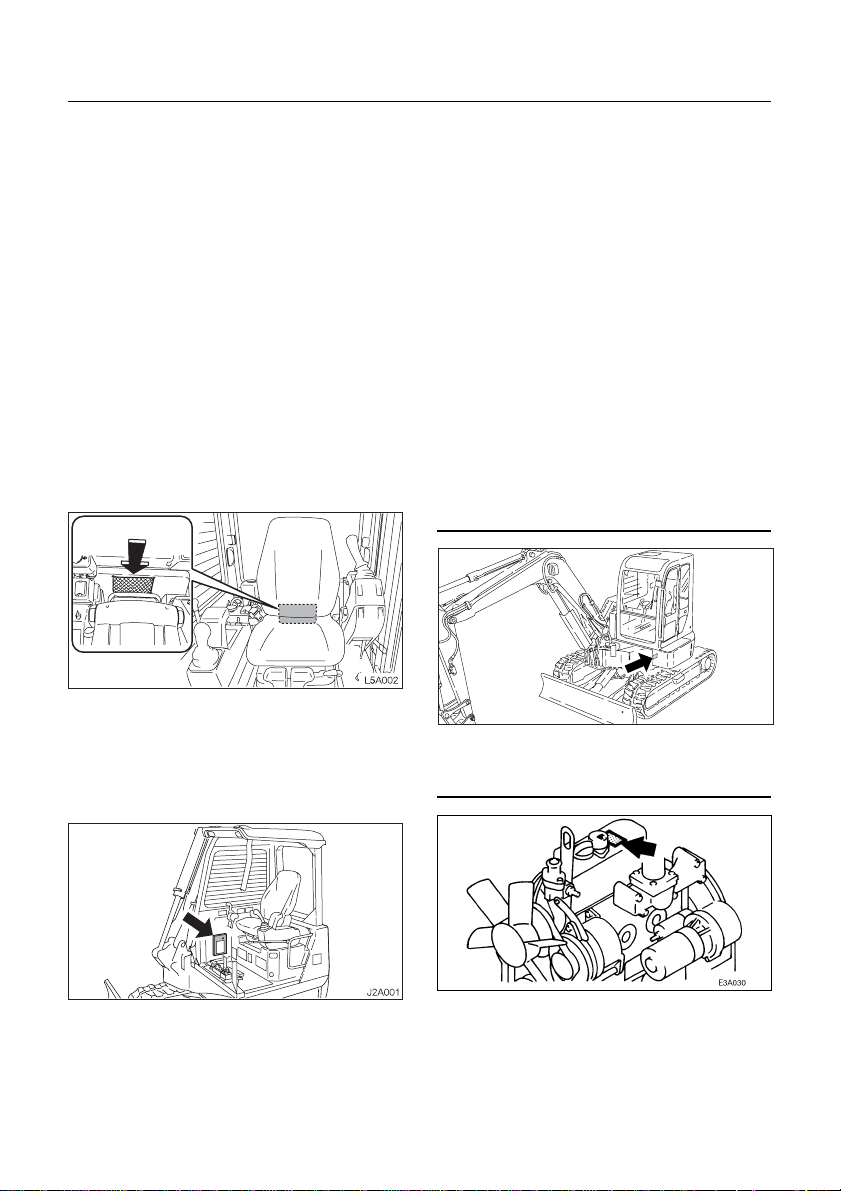
■ Manual storage compartment
A compartment for storing this manual is
provided at the position shown on the
diagram below.
1. After using the manual, place it in the
plastic pouch and store it back in the
manual storage compartment.
< TB153FR : Canopy >
■ Serial numbers
Check the serial numbers of the machine and
the engine and write them in the spaces
provided below.
Machine number :
L4A0011
Engine number :
1. Insert the starter key and turn it
counterclockwise to unlock the manual
storage compartment.
2
Page 5
MACHINE DESCRIPTlON
■ Front, rear, Ieft and right
This manual refers the front, rear, left and
right of the machine as seen when sitting in
the operator’s seat with the dozer blade
visible to the front.
■ Designated operations
Use this machine primarily for the following
operations:
¡ Excavating
¡ Digging ditches
¡ Digging side ditches
¡ Leveling
¡ Loading
■ Features
¡ A unique adjustable offset boom system
¡ Short tail swing radius
¡ Short pitch rubber crawler
¡ Low engine noise and exhaust emissions
¡ Pilot operated joystick controls
¡ One toutch engine deceleration button
¡ Slew cushioning system for easy bucket positioning
¡ Engine emergency stop / idle system
¡ Tilt-up operators platform for easy access to major compartment
FRONT
REAR
RIGHTLEFT
D5A003
■ Break-in period
When the machine is new, heed the instructions below when operating the machine for the
first 100 hours (as indicated on the hour meter).
Using a new machine roughly without breaking it in will lead to quicker deterioration of machine
performance and may shorten the machine’s service life.
¡ Warm up the engine and hydraulic oil sufficiently .
¡ Avoid heavy loads and rapid operations. Operate with a load of about 80% the maximum
load.
¡ Do not start up, accelerate, change directions, or stop abruptly unless necessary.
3
Page 6

4
Page 7

CONTENTS
Introduction .................................... 2
Machine Description ...................... 3
Safety.............................................. 7
Controls .........................................35
Operation.......................................67
Transport .....................................101
Maintenance ................................107
Troubleshooting ..........................161
Specifications..............................175
Options ........................................193
Index ............................................229
5
Page 8

6
Page 9

SAFETY
General Precautions ....................................8
Preparing Precautions...............................12
Starting Precautions ..................................14
Operating Precautions...............................16
Stopping Precautions ................................23
Transporting Precautions ..........................24
Maintenance Precautions ..........................25
Safety Signs (Decals).................................32
7
Page 10
SAFETY
General Precautions
Observe all safety rules
¡ Operation, inspection and maintenance of
this machine must be performed only by
a trained and qualified person.
¡ All rules, regulations, precautions and
safety procedures must be understood
and followed when performing operation,
inspection and maintenance of this
machine.
¡ Do not perform any operation, inspection
and maintenance of this machine when
under the adverse influence of alcohol,
drugs, medication, fatigue, or insufficient
sleep.
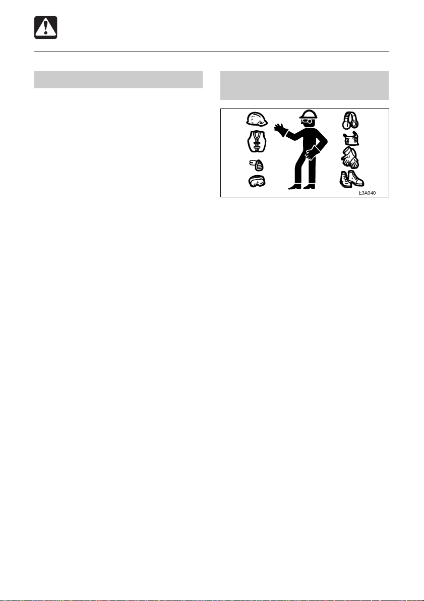
Wear appropriate clothing and personal protective equipment
¡ Do not wear loose clothing or any
accessory that can catch on controls or in
moving parts.
¡ Do not wear oily or fuel stained clothing
that can catch fire.
¡ Wear a hard hat, safety shoes, safety
glasses, filter mask, heavy gloves, ear
protection and other protective equipment
as required by job conditions. Wear
required appropriate equipment such as
safety glasses and filter mask when using
grinders, hammers or compressed air, as
metal fragments or other objects can fly
and cause serious injury.
¡ Use hearing protection when operating the
machine. Loud prolonged noise can cause
hearing impairments, even the total loss
of hearing.
8
Page 11
SAFETY
General Precautions
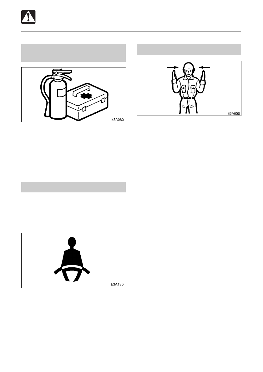
Provide a fire extinguisher and first aid kit
¡ Know where a fire extinguisher and first
aid kit are located and understand how to
use them.
¡ Know how to contact emergency
assistance and first aid help.
Never remove safety equipment
¡ Make sure all protective guards, canopies,
doors, etc., are in place and secure. Repair
or replace damaged components before
operating the machine.
Use a signal person and flagman
Know and use the hand signals required for
particular jobs and make sure who has the
responsibility for signaling.
¡ All personnel must fully understand all the
signals.
¡ The operator shall respond to signals only
from the appointed signal person, but shall
obey a stop signal at any time from
anyone.
¡ The signal person must stand in a clearly
visible location when giving signals.
¡ Know how to use the safety lock lever , seat
belt and other safety equipment and use
them properly .
¡ Never remove any safety equipment
except for service. Keep all safety
equipment in good operating condition.
9
Page 12

SAFETY
General Precautions
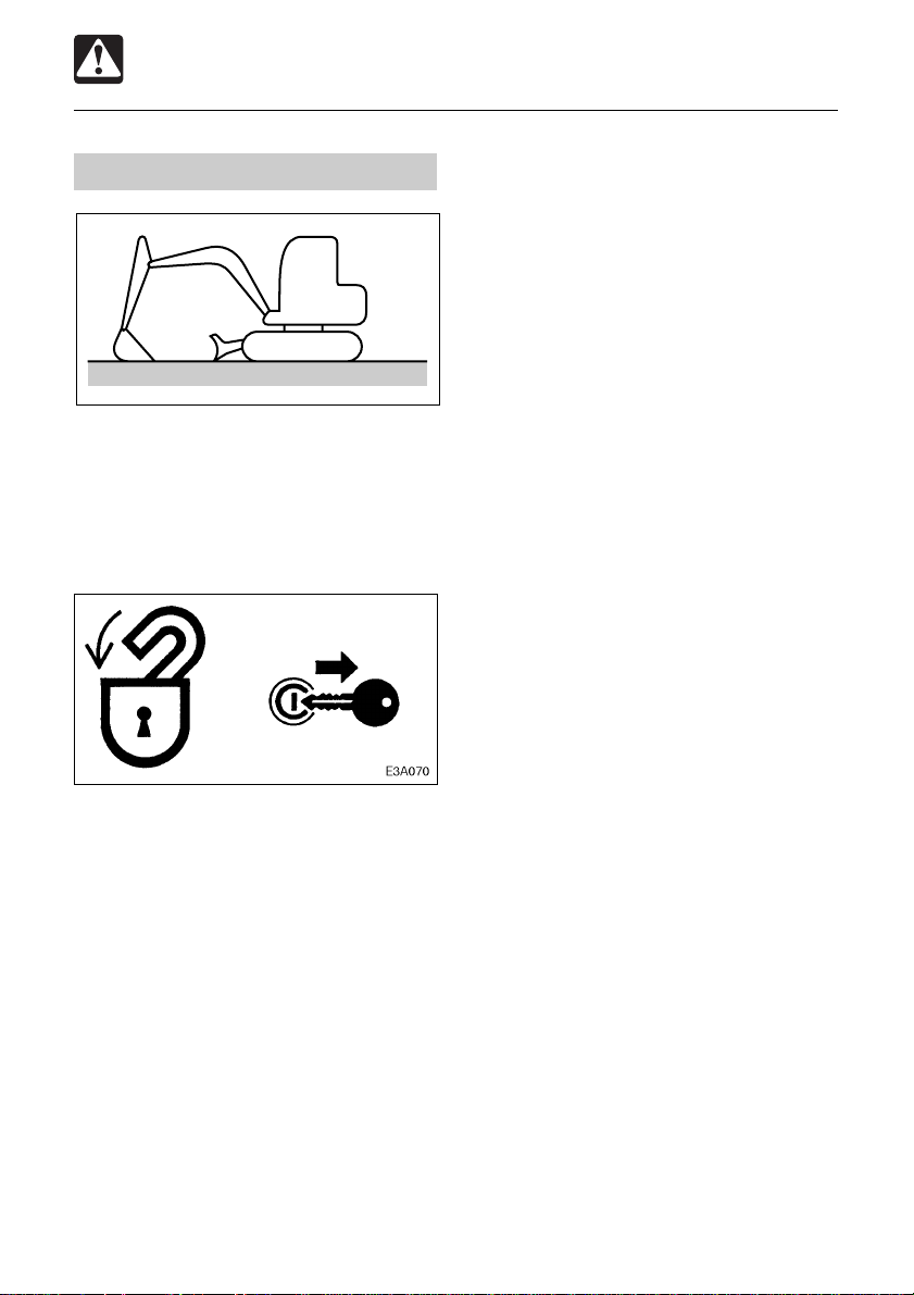
Be sure to lock the safety lock lever before leaving the operator’s seat
¡ Before leaving the operator’s seat, raise
the safety lock lever to engage the lock
and stop the engine. If any controls should
be touched accidentally when the safety
lock lever is lowered, the machine will
move suddenly, and cause serious injury
or death.
¡ < TB153FR > : Note that the dozer blade
control is not locked, even when the safety
lock lever is set to the lock position. Do
not touch this control accidentally.
¡ Before leaving the operator’s seat, lower
the working equipment, raise the safety
lock lever to engage the lock and stop the
engine. Also, be sure to remove the key
and take it with you.
Avoid fire and explosion hazards
Keep flames away from fuel, hydraulic fluid,
oil, grease and antifreeze. Fuel is particularly
flammable and dangerous.
¡ When handling these combustible
materials, keep lit cigarettes, matches,
lighters and other flames or sources of
flames away.
¡ Do not smoke or permit open flames while
fueling or near fueling operations.
¡ Never remove the fuel cap or refuel with
the engine running or hot. Never allow fuel
to spill on hot machine components.
¡ Clean up spilled fuel, oil or other
flammable fluids immediately.
¡ Check for fuel, oil or hydraulic fluid leaks.
Stop all leaks and clean the machine
before operating.
¡ Do not cut or weld on pipes or tubes that
contain flammable fluids. Clean thoroughly
with nonflammable solvent before cutting
or welding.
¡ Remove all trash or debris from the
machine. Make sure that oily rags or other
flammable material are not stored on the
machine.
¡ Handle all solvents and dry chemicals
according to procedures identified on
manufacturers’ containers. Work in a wellventilated area.
¡ Never use fuel for cleaning purposes.
Always use a nonflammable solvent.
¡ Store all flammable fluids and materials
in a safe and well-ventilated place.
10
Page 13
SAFETY
General Precautions
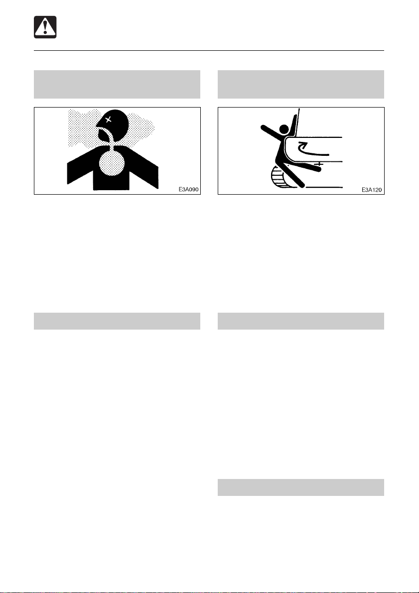
Exhaust fumes from the engine can kill
¡ Do not operate the engine in an enclosed
area without adequate ventilation.
¡ If natural ventilation is poor, install
ventilators, fans, exhaust extension pipes
or other artificial venting devices.
Handling asbestos dust
Inhaling asbestos dust has been linked to
lung cancer. When handling materials which
may contain asbestos, take the following
precautions:
¡ Never use compressed air for cleaning.
¡ Avoid brushing or grinding of the materials.
¡ For clean up, use wet methods or a
vacuum equipped with a high efficiency
particulate air (HEP A) filter.
¡ Wear an approved respirator if there is no
other way to control the dust. When
working indoors, install a ventilation
system with a macro molecular filter.
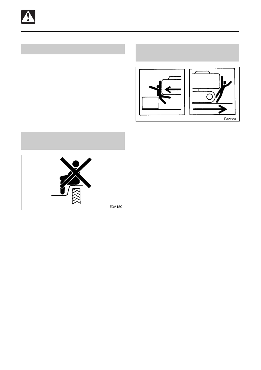
Be careful not to get crushed or cut
Never put your hands, feet or other parts of
your body between the upperstructure and
the undercarriage or tracks, between the
machine body and working equipment, or
between a cylinder and moving part. The size
of these gaps change when the machine
moves and if caught a person can suffer
severe injury or death.
Using optional products
¡ Consult with a Takeuchi dealer before in-
stalling optional attachments.
¡ Do not use attachments that have not
been approved by T akeuchi or a Takeuchi
dealer. Doing so may compromise safety
or adversely affect the machine’s
operation or service life.
¡ Takeuchi will not be held responsible for
any injuries, accidents or damage to its
products caused by the use of a nonapproved attachment.
Never modify the machine
Unauthorized modifications to this machine
can cause injury or death. Never make
unauthorized modifications to any part of this
machine.
11
Page 14
SAFETY
Preparing Precautions
Know the working area
Before starting operation, know the working
area to ensure safety.
¡ Check the topography and ground
condition of the working area, or the
structure of the building when working
indoors, and take the necessary safety
measures in dangerous spots.
¡ Note and avoid all hazards and
obstructions such as ditches, underground
lines, trees, cliffs, overhead electrical wires
or areas where there is danger of a slide.
¡ Check with the local utilities for the
locations of buried gas and water pipes
and buried power cables. Determine jointly
what specific precautions must be taken
to insure safety.
¡ When working on roads, be sure to take
into account the safety of pedestrians and
vehicles.
• Use a flagman an / or signals.
• Fence off the working area and prohibit
entry to unauthorized persons.
¡ When working in water or crossing shallow
streams or creeks, check the depth of the
water, the solidity of the ground, and the
speed of the current beforehand. Make
sure the water is not deeper than the
allowable depth.
Refer to the section titled “Cautions on
Operating” for further instructions.
Alway keep the machine clean
¡ Clean windows, mirrors and lights to
ensure good visibility .
¡ Wipe off any oil, grease, mud, snow or
ice, to prevent accidents due to slipping.
¡ Remove all loose objects stored in the
machine and all objects which do not
belong in or on the machine and its
equipment.
¡ Remove any dirt, oil or grease from the
engine area, to prevent fires.
¡ Clean the area around the operator’s seat,
removing any potential obstacles.
12
Page 15

SAFETY
Preparing Precautions
Perform inspection and maintenance daily
Failure to notice or repair machine
irregularities or damage can lead to
accidents.
¡ Before operating, perform the prescribed
inspections and make repairs immediately
should any irregularities be found.
¡ If a failure that causes loss of control such
as steering, service brakes or engine
occurs, stop the machine motion as
quickly as possible, follow the shutdown
procedure, and keep machine securely
parked until the malfunction is corrected.
13
Page 16
SAFETY
Starting Precautions
Maintain three point contact when mounting and dismounting
¡ Do not jump on or off the machine. Never
attempt to mount or dismount a moving
machine.
¡ When mounting and dismounting the cab,
first open the door fully to the locked
position and check that it does not move.
(For machines with cabs)
¡ Always face the access system and
maintain a three point contact with the
recommended handrails and steps while
getting on and off the machine. Keep steps
and platform clean.
¡ Never use the safety lock lever or control
levers as hand holds.
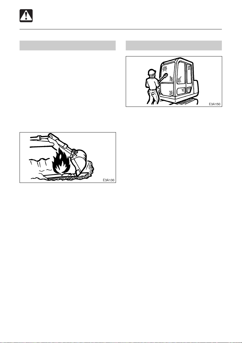
Clear the area of other persons before starting the machine
Do not start the engine until you are sure it is
safe. Before starting, check or perform the
following.
¡ Walk around the machine and warn all
personnel who may be servicing the
machine or are in the machine path. Do
not start until all personnel are clearly away
from the machine.
¡ Check for any “DO NOT OPERATE” tags
or similar warning notices on the cab door,
controls or starter switch.
¡ Sound horn to alert everyone around the
machine.
Start the engine from the operator’s seat
¡ Adjust, secure and latch the operator’s
seat.
¡ Fasten the seat belt.
¡ Check that the parking device is applied
and place all controls in the neutral
position.
¡ Check that the safety lock lever is in the
lock position.
¡ Clear the area of all persons.
¡ Start and operate the engine from the
operator’s seat only.
¡ Never attempt to start the engine by
shorting across the starter terminals.
14
Page 17

SAFETY
Starting Precautions
Starting with jumper cables
Use jumper cables only in the recommended
manner. Improper use of jumper cables can
result in battery explosion or unexpected
machine motion.
Refer to the section titled “If the Battery
Goes Dead” for proper instructions.
After starting the engine
After starting the engine, perform the
following operations and checks in a safe
place with no persons or obstacles in the
area. If any malfunctions are found, follow
the shutdown procedure and report the
malfunction.
¡ Warm up the engine and hydraulic fluid.
¡ Observe all gauges or warning
instruments for proper operation.
¡ Listen for unusual noises.
¡ Test engine speed control.
¡ Operate each control to insure proper
operation.
In cold weather
¡ Be careful of slippery conditions on
freezing ground, steps and hand holds.
¡ In severe cold weather, do not touch any
metal parts of the machine with exposed
flesh, as flesh can freeze to the metal and
Cause injury.
¡ Do not use ether or starting fluids on this
engine. These starting aids can cause
explosion and serious injury or death.
¡ Warm up the engine and hydraulic fluid
before operating.
15
Page 18
SAFETY
Operating Precautions
Ensure good visibility
¡ When working in dark places, turn on the
machine’s working lights and headlights
and/or provide extra stationary lighting if
necessary.
¡ When visibility is poor due to severe
weather (fog, snow or rain), stop operating
the machine and wait until conditions
improves.
Do not permit riders on the machine
¡ Do not allow anyone to ride on any part of
the machine at any time while traveling.
¡ Do not allow anyone to be on any part of
the machine while operating.
Check for safety in the surrounding area before starting
¡ Understand the machine limitations.
¡ Use a signal person where clearances are
close or your vision is obstructed.
¡ Never allow anyone to enter the slewing
(swing) radius and machine path.
¡ Signal your intention to move by sounding
the horn.
¡ There are blind spots to the rear of the
machine.
If necessary, swing the cab around before
backing up to check that the area is safe
and clear.
16
Page 19
SAFETY
Operating Precautions
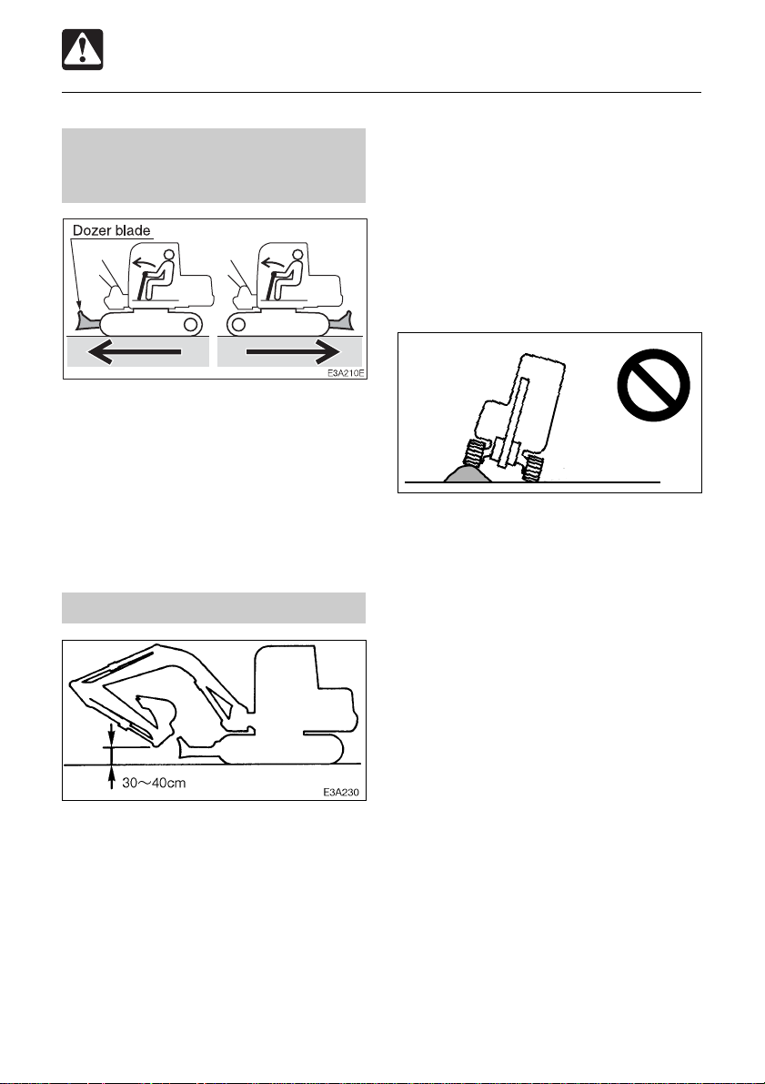
Check the position of the undercarriage (tracks) before traveling
Before operating the travel levers, check to
make sure that the dozer blade is to the front
of the operator’s seat. BE A WARE that when
the dozer blade is to the rear of the operator’s
seat, the travel levers operate in the opposite
direction to when the dozer blade is in the
front.
Travel safety
(12 to 16 in.)
¡ When a load greater than a set value is
applied during 2nd speed (high speed)
travel, the speed will automatically slow
down by switching to 1st speed (low
speed). Thereafter, when the load
becomes lighter, the speed will increase
by returning to 2nd speed (high speed).
Exercise due caution since the travel
speed changes automatically.
E4A040
¡ Avoid crossing over obstacles whenever
possible. If you must do so, keep the hoe
attachment close to the ground and travel
slowly. Never cross obstacles if they will
seriously tilt the machine (to an angle of
10° or greater).
¡ On uneven ground, travel at low speed
and avoid accelerating, stopping or
changing directions abruptly.
¡ When roading a machine, know and use
the signaling devices required on the
machine. Provide an escort for road travel
when required.
¡ Travel with the dozer blade up, the hoe
attachment folded as shown on the
diagram, and the bucket raised 30 to 40
cm (12 to 16 in.) from the ground.
¡ Do not slew (swing) while traveling. If you
must operate the hoe attachment while
traveling, operate at speeds slow enough
so you have complete control at all times.
17
Page 20
SAFETY
Operating Precautions
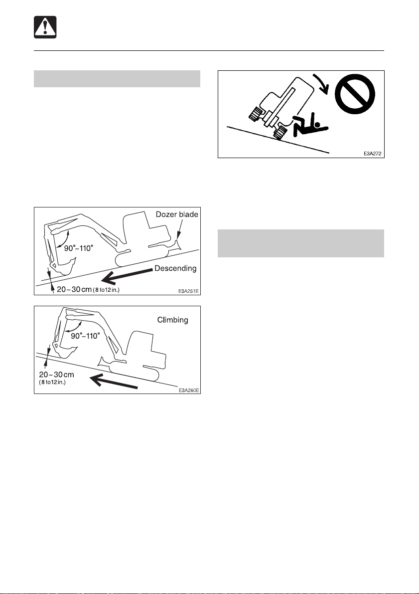
Cautions on traveling on slopes
When traveling on slopes or grades, be
careful that the machine does not tip (roll)
over or slide.
¡ Never exceed the machine’s stability
capabilities (maximum gradeability - 30°,
lateral tipping angle - 15°). Also note that
when actual working area conditions are
poor the machine’s stability capabilities
may be lower.
¡ Do not change directions or cross slopes
sideways. First return to a flat surface then
redirect the machine.
Operate on snow or ice with extra care
¡ When traveling on snow or frozen
surfaces, keep the machine travel speed
down and avoid accelerating, stopping or
changing directions abruptly .
¡ Remember that the road shoulder , fences,
etc., may be buried in the snow and not
visible.
¡ Lower the dozer blade when parked on
unsure ground conditions.
¡ When traveling on slopes or grades, lower
the bucket to a height of 20 to 30 cm (8 to
12 in.) off the ground. In emergencies,
lower the bucket to the ground and stop
the machine.
¡ When traveling on slopes or grades, move
slowly in first gear (low speed).
¡ Do not travel down slopes in reverse.
¡ On grass, dead leaves, wet metal or frozen
surfaces, the machine may slide sideways
even on very gentle slopes. Make sure
the machine never faces sideways with
respect to the slope.
18
Page 21
SAFETY
Operating Precautions
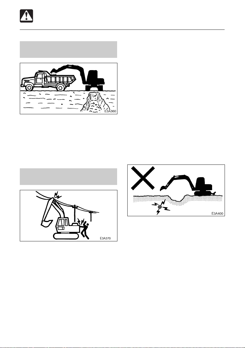
Insure driver safety before loading trucks
Do not load a truck unless the driver is in a
safe place.
¡ Never swing or position the bucket over
personnel or truck cabs.
¡ Load the truck from the rear.
Keep a safe distance from electrical power lines
¡ Always contact the nearest electric utility
and determine jointly what specific
precautions must be taken to insure safety.
¡ Consider all lines to be power lines and
treat all power lines as energized even
though it is known or believed that the
power is shut off and the line is visibly
grounded.
¡ Use a signal person to observe the
approach of any part of the machine or
load to the power line.
¡ Caution all ground personnel to stand
clear of the machine and the load at all
times.
¡ If the machine should come in contact with
a live electrical source, do not leave the
operator’s seat. Do not allow anyone to
approach or touch the machine.
Never approach power lines with any part of
the machine and its load unless all local and
national required safety precautions have
been taken. Electrocution and death can
result from arcing, touching or even being
close to a machine that is in contact with or
near an electrical source.
¡ Maintain the maximum possible distance
from power lines and never violate the
minimum clearance.
¡ Be especially careful of buried high voltage
power lines.
19
Page 22
SAFETY
Operating Precautions
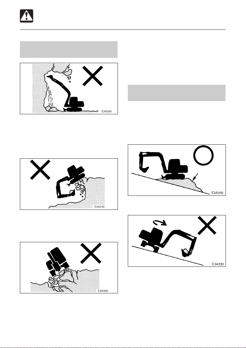
Watch out for hazardous working conditions
¡ Never undercut a high bank. Be
particularly alert for the possibility of a
cave-in.
¡ Do not operate in places where there is a
danger of falling rocks.
• The ground is weak after rain or
explosions.
• The ground is also unstable on banks
and near dugout trenches.
Operating on slopes is dangerous
When operating on slopes or grades, slewing
(swinging) or operating working equipment
may cause the machine to lose stability and
tip over. Avoid operating on slopes whenever
possible.
Fill
¡ Level off the work area.
¡ Keep machine well back from the edge of
an excavation. Avoid undercutting the
machine.
¡ Do not approach unstable surfaces (cliffs,
road shoulders, deep trenches, etc.). The
ground may give way under the machine’s
weight or vibrations, causing the machine
to tip over.
¡ Avoid swinging the loaded bucket in a
downhill direction. This will reduce the
stability of the machine.
20
Page 23
SAFETY
Operating Precautions
Never slew (swing) sideways with excessive weights
The machine can tip over more easily in the
lateral direction than in the longitudinal
direction.
¡ Do not slew (swing) sideways with
excessive weight at the front.
In particular do not slew sideways on
slopes.
¡ The front is heavier for machines equipped
with breakers, crushers or telescopic arms
than for machines equipped with the
standard bucket. Do not operate such
machines sideways especially with the
digging arm (boom) downhill.
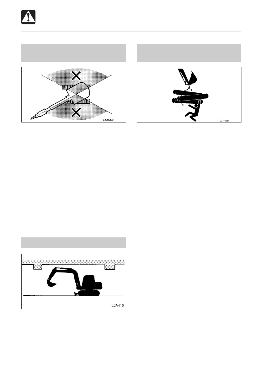
Watch boom clearance
When operating under bridges, in tunnels,
near power lines or indoors, be careful not
to hit the boom or arm against overhead
objects.
Excavators are not designed for lifting loads
The machine is specifically designed for
excavation work and has no safety devices
for crane operation. Extreme caution should
be used if the excavator is used for lifting.
¡ Never lift loads in excess of capacity.
Overload will cause the machine to roll and
can result in serious injury or death.
¡ All rated lift capacities are based on the
machine being level and on a firm
supporting surface. For safe working
loads, the user is expected to make due
allowance for the particular job conditions
such as soft or uneven ground, non-level
condition, side loads, dynamic or jerked
loads, hazardous conditions, experience
of personnel, etc. The operator and other
personnel should fully acquaint
themselves with the operator’s manual
before operating this machine, and rules
for safe operation of equipment shall be
adhered to at all times.
¡ Failure of the bucket linkage or slings
could result if chains or slings are
incorrectly attached, resulting in serious
injury or death.
¡ Do not attempt to pull stumps out of the
ground while using the machine as a
crane. The loads imposed on the machine
under this use are completely unknown.
¡ Never allow any personnel to stand on or
under lifted loads or even within the
maneuvering area.
21
Page 24

SAFETY
Operating Precautions
Danger of flying objects
This machine is not equipped with protective
guards to protect the operator from flying
objects. Do not use the machine in places
where there are risks of the operator being
hit by flying objects.
Cautions on towing
N0A006
When towing, selecting the wrong wire rope,
inspecting improperly, or towing in the wrong
way could lead to accidents resulting in
serious injury or death.
¡ The wire rope breaking or coming
detached could be extremely dangerous.
Use a wire rope suited for the required
towing force.
¡ Do not use a wire rope that is kinked,
twisted or otherwise damaged.
¡ Do not apply strong loads abruptly to the
wire rope.
¡ Use safety gloves when handling the wire
rope.
¡ Make sure there is an operator on the
machine being towed as well as on the
machine that is towing.
¡ Never tow on slopes.
¡ Do not let anyone near the wire rope while
towing.
22
Page 25
SAFETY
Stopping Precautions
Park safely
E3A4901
¡ Park the machine on firm, level ground and
apply the parking device.
¡ When parking on streets, use barriers,
caution signs, lights, etc., so that the
machine can easily be seen even at night
to avoid collision with other vehicles.
¡ Before leaving the machine, do the
following:
1. Lower the bucket and dozer blade to
the ground.
2. Raise the safety lock lever to engage
the lock.
3. Stop the engine and remove the key.
4. Lock the cab and covers.
23
Page 26
SAFETY
Transporting Precautions
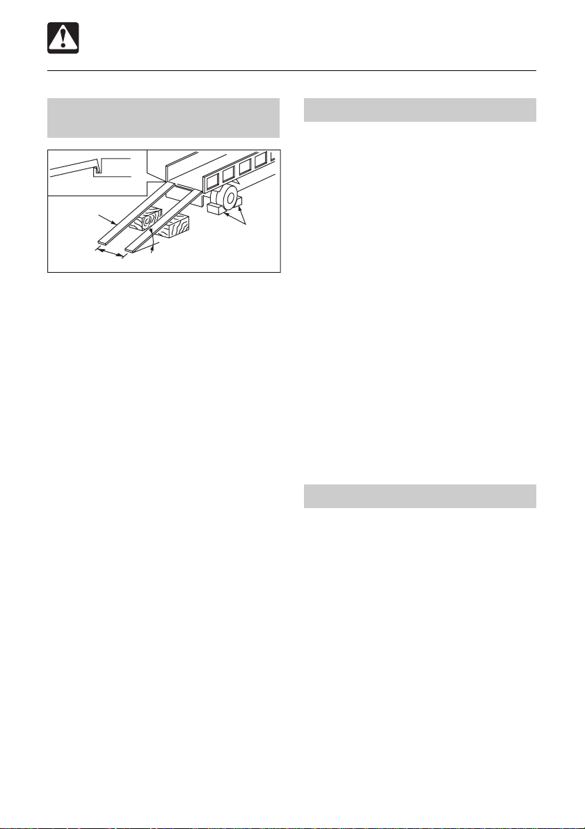
Load and unload the machine safely
Fasten to the suspension fitting
Ramp
Stopper
Distance between ramps
The machine may roll or tip over or fall while
loading or unloading it. Take the following
precautions:
¡ Select a firm, level surface and keep
sufficient distance from road shoulders.
¡ Use loading ramps of adequate strength
and size. Maintain the slope of loading
ramps within 15 degrees.
¡ Secure the ramps to the truck bed.
¡ Keep the truck bed and loading ramps
clean of oil, clay, ice, snow, and other
materials which can become slippery.
Clean the tracks.
¡ Block the transport vehicle so it can not
move.
¡ Use a signal person when loading and
unloading the machine, and travel slowly
in first gear (low speed).
¡ Never change course on the ramp.
¡ Do not slew (swing) on ramps. The
machine may tip over.
¡ When slewing (swinging) on the truck bed,
do so slowly as the footing can be
unstable.
¡ Engage the slew (swing) lock after loading.
¡ Block both tracks and secure the machine
to the truck bed with load binders.
15° or less
E4F001
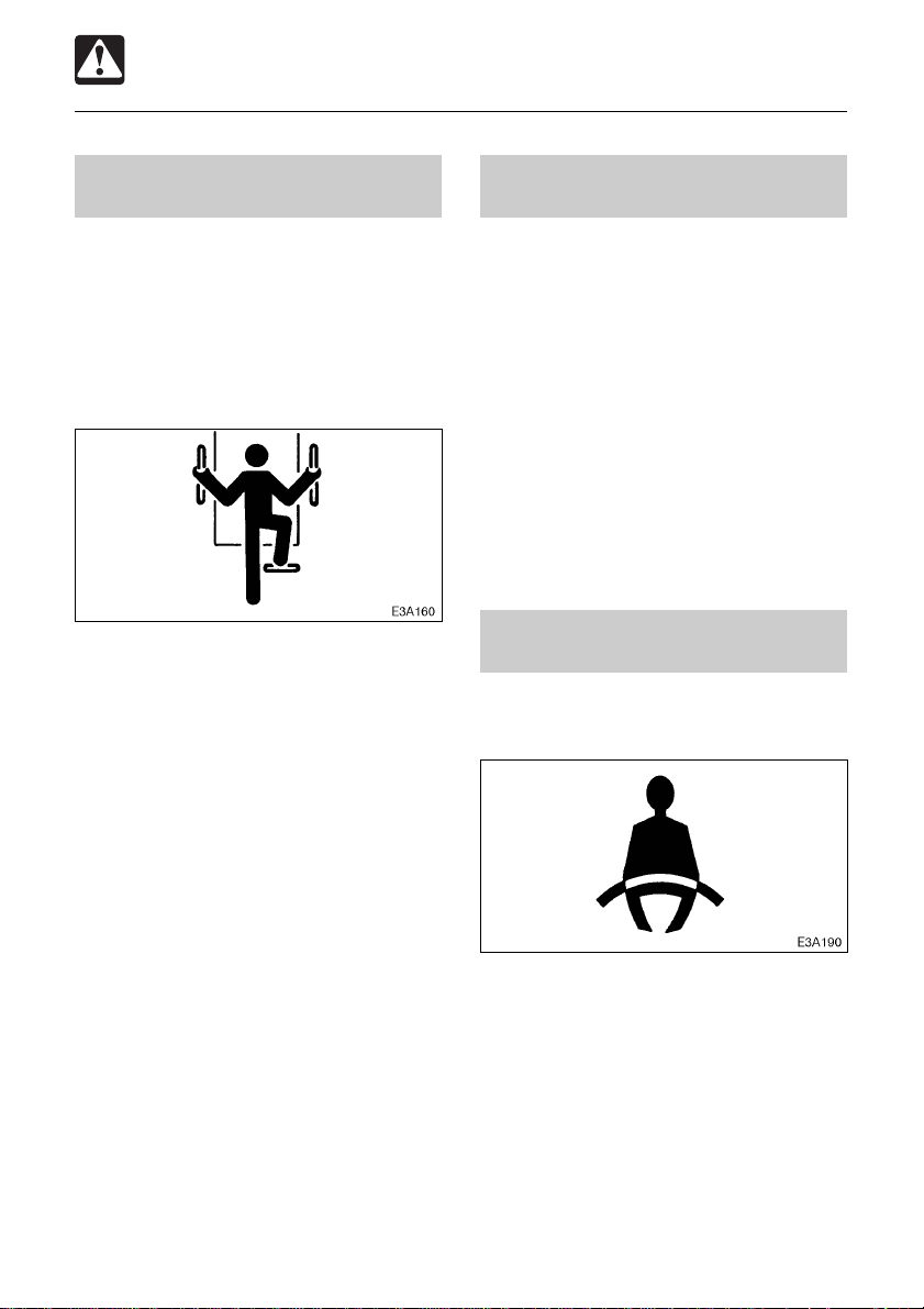
Hoist the machine safely
¡ Know and use correct crane signals.
¡ Inspect the hoisting equipment daily for
damaged or missing parts.
¡ When hoisting, use a wire rope with
sufficient strength with respect to the
machine’s weight.
¡ Do not hoist with the machine in a posture
other than the one described in the
procedure below. Doing so is dangerous
as it may result in the machine losing its
balance.
Refer to the section titled “Hoisting the
Machine” for further instructions.
¡ Do not hoist the machine with an operator
(s) on it.
¡ When hoisting, hoist slowly so that the
machine does not tip.
¡ Keep all other persons out of the area
when hoisting. Do not move the machine
over the heads of the persons.
Transport the machine safely
¡ Know and follow the safety rules, vehicle
code and traffic laws when transporting
the machine.
¡ Consider the length, width, height and
weight of the truck with the machine
loaded on it when determining the best
route.
24
Page 27
SAFETY
Maintenance Precautions
Attach a “DO NOT OPERA TE” tag
Severe injury could result if an unauthorized
person should start the engine or touch
controls during inspection or maintenance.
¡ Stop the engine and remove the key
before performing maintenance.
¡ Attach a “DO NOT OPERATE” tag to the
starter switch or control lever.
Use the correct tools
Do not use damaged or weakened tools or
tools designed for other purposes. Use tools
suited for the operation at hand.
Anti-explosive lighting
Use anti-explosive electrical fixtures and
lights when inspecting fuel, oil, coolant,
battery fluid, etc. If lighting that is not antiexplosive should break, the substance could
ignite, resulting in serious injury or death.
Do not allow unauthorized personnel in the work area
Replace important safety parts periodically
¡ Replace fuel hoses periodically. Fuel
hoses become weaker over time, even if
they appear to be in good shape.
¡ Replace important safety parts whenever
an irregularity is found, even if it is before
the normal time for replacement.
Refer to the section titled “Important Parts”
for further details.
Do not allow unauthorized personnel in the
work area. Chips or other debris can fly off
machine parts when grinding, welding or
using a hammer.
25
Page 28
SAFETY
Maintenance Precautions
Prepare the work area
¡ Select a firm, level work area. Make sure
there is adequate light and, if indoors,
ventilation.
¡ Clear obstacles and dangerous objects.
Eliminate slippery areas.
Always clean the machine
Stop the engine before performing maintenance
¡ Avoid lubrication or mechanical
adjustments with the machine in motion
or with the engine running while stationary.
¡ If maintenance must be performed with
the engine running, always work as a two
person team with one person sitting in the
operator’s seat while the other works on
the machine.
• When performing maintenance, be sure
to keep your body and clothing away
from moving parts.
Stay clear of moving parts
¡ Clean the machine before performing
maintenance.
¡ Stop the engine and cover electrical parts
when washing the machine. Water on
electrical parts could cause short-circuits
or malfunctions.
Do not use water or steam to wash the
battery, sensors, connectors or the
operator’s seat area.
¡ Stay clear of all rotating and moving parts.
Wrapping or entanglement may result in
serious injury or death.
¡ Keep hands, clothing and tools away from
the rotating fan and running fan belts.
26
Page 29
SAFETY
Maintenance Precautions
Securely block the machine or any component that may fall
¡ Before performing maintenance or repairs
under the machine, set all working
equipment against the ground or in the
lowermost position.
¡ Securely block the tracks.
¡ If you must work beneath the raised
machine or equipment, always use wood
blocks, jack-stands or other rigid and
stable supports. Never get under the
machine or working equipment if they are
not sufficiently supported. This procedure
is especially important when working on
hydraulic cylinders.
Secure the engine hood or cover when opened
Be sure to secure the engine hood or cover
when opening it. Do not open the engine
hood or cover on slopes or in strong wind.
Cautions on tilting up the platform
¡ Raising or lowering the platform while the
engine is running may cause the machine
to move, and cause serious injury or
death. Lower the working equipment to the
ground and stop the engine before raising
or lowering the platform.
¡ When the floor is tilted up, support it firmly
with the stopper to prevent it from falling.
Place heavy objects in a stable position
Securely block the working equipment
To prevent unexpected movement, securely
block the working equipment when repairing
or replacing the cutting edges or bucket teeth.
When removing or installing the hoe
attachment, place it in a stable position so
that it does not tip over.
27
Page 30
SAFETY
Maintenance Precautions
Use caution when fueling
¡ Do not smoke or permit open flames while
fueling or near fueling operations.
¡ Never remove the fuel cap or refuel with
the engine running or hot. Never allow fuel
to spill on hot machine components.
¡ Maintain control of the fuel filler nozzle
when filling the tank.
¡ Do not fill the fuel tank to capacity. Allow
room for expansion.
¡ Clean up spilled fuel immediately.
¡ Tighten the fuel tank cap securely. Should
the fuel cap be lost, replace it only with
the original manufacturer’s approved cap.
Use of a non-approved cap without proper
venting may result in pressurization of the
tank.
¡ Never use fuel for cleaning purposes.
¡ Use the correct fuel grade for the operating
season.
Be careful with hot and pressurized components
Stop the engine and allow the machine to
cool down before performing inspection and
maintenance.
¡ The engine, muffler, radiator, hydraulic
lines, sliding parts and many other parts
of the machine are hot directly after the
engine is stopped. Touching these parts
will cause burns.
¡ The engine coolant, oil and hydraulic fluid
are also hot and under high pressure.
Be careful when loosening caps and
plugs. Working on the machine under
these conditions could result in burns or
injuries due to the hot oil spurting out.
Be careful with hot cooling systems
Handling of hoses
Fuel, oil or hydraulic fluid leaks can cause a
fire.
¡ Do not twist, bend or hit the hoses.
¡ Never use twisted, bent or cracked hoses,
tubes and pipes. They may burst.
¡ Retighten loose connections.
Do not remove the radiator cap or drain plugs
when the coolant is hot. Stop the engine, let
the engine and radiator cool and loosen the
radiator cap or drain plugs slowly.
28
Page 31

SAFETY
Maintenance Precautions
Be careful with fluids under pressure
Pressure can be maintained in the hydraulic
circuit long after the engine has been shut
down.
¡ Release all pressure before working on
the hydraulic system.
¡ Hydraulic fluid under pressure can
penetrate the skin or eyes and cause
injury , blindness or death. Fluid escaping
from a small hole can be almost invisible.
Wear a safety goggles and heavy gloves
and use a piece of cardboard or wood to
search for suspected leaks.
If fluid is injected into the skin, it must be
removed within a few hours by a doctor
familiar with this type of injury .
Release all pressure before working on the hydraulic system
Oil may spurt out if caps or filters are removed
or pipes disconnected before releasing the
pressure in the hydraulic system.
¡ Gradually press the air breather button to
relieve tank pressure.
¡ Move all the control levers and pedals
several times in all directions to release
the pressure from the working equipment
circuitry. (When equipped with accumulator)
¡ When removing plugs or screws or
disconnecting hoses, stand to the side and
loosen slowly to gradually release the
internal pressure before removing.
Handling of the accumulator
High pressure nitrogen gas is enclosed in
the accumulator and incorrect handling could
possibly bring about serious personal injury
due to explosion. The following matters
should be strictly observed :
¡ Do not disassemble.
¡ Do not bring close to fire or throw into a
fire.
¡ Do not make hole, weld, or fuse.
¡ Do not subject to shock such as hitting or
rolling.
¡ At time of disposal, it will be necessary to
release the enclosed gas. Please contact
a Takeuchi sales or service outlet.
29
N0A0051
Page 32

SAFETY
Maintenance Precautions
Be careful with grease under pressure < TB153FR >
E3A6201
The track adjuster contains highly
pressurized grease. If the tension is adjusted
without following the prescribed procedure,
the grease discharge valve may fly off,
resulting in injury.
¡ Do not loosen the grease nipple.
¡ Loosen the grease discharge valve slowly .
¡ Do not put your face, arms, legs or body
in front of the grease discharge valve.
¡ If no grease is expelled when grease
discharge valve is loosened, there is a
problem. Contact your nearest service
outlet for repairs. DO NOT disassemble,
as this is very dangerous.
Disconnect the battery
Disconnect the battery before working on the
electrical system or doing any welding.
Remove the negative (–) battery cable first.
When reconnecting the battery, connect the
negative (–) battery cable last.
Avoid battery hazards
¡ Batteries contain sulfuric acid which will
damage eyes or skin on contact.
• If acid contacts eyes, flush immediately
with clean water and get prompt medical
attention.
• If acid is accidentally swallowed, drink
large quantities of water or milk and call
a physician immediately.
• If acid contacts skin or clothing, wash
off immediately with clean water.
¡ Wear safety glasses and gloves when
working with batteries.
¡ Batteries generate flammable and
explosive gases. Keep arcs, sparks,
flames and lighted tobacco away.
¡ Use a flashlight to check battery electrolyte
level.
¡ Stop the engine and shut off electrical
equipment while inspecting or handling the
battery .
¡ Do not short circuit the battery posts with
metal items.
¡ Always unfasten the negative (–) battery
cable first when disconnecting the battery
cable. Always connect the negative (–)
battery cable last when fastening the
battery cable.
¡ Loose battery terminals may result in
sparks. Be sure to fasten terminals tightly.
¡ Make sure the vent caps are tightened
securely.
¡ Do not charge a battery or jump-start the
engine if the battery is frozen. Warm to
15°C (60°F) or the battery may explode.
¡ Do not use the battery when the fluid level
is below the lower level. Doing so will
hasten the deterioration of the internal
portions of the battery and shorten the
battery life, and can also cause rupturing
(or an explosion).
¡ Do not fill the battery above the upper
level. Doing so could cause the fluid to
leak, contact and damage the skin, or
cause parts to corrode.
30
Page 33

SAFETY
Maintenance Precautions
Have a T akeuchi service agent repair welding cracks or other damage
Ask a Takeuchi service agent to repair any
welding problems which are detected. If not
feasible, make sure the welding is done by a
qualified person in a properly equipped
workplace.
Vibrations to which the operator is subjected
According to the results of the tests carried
out to determine the vibrations transmitted
to the operator by the machine, the upper
limbs are subjected to vibrations lower than
2.5 m (8.2 ft) / sq.sec. while the seated part
of the body is subjected to vibrations lower
than 0.5 m (1.64ft) / sq.sec.
Checks after maintenance
Disposing of wastes
¡ Funnel spent fluids from the machine into
containers. Disposing of fluids improperly
destroys the environment.
¡ Follow the prescribed regulations when
disposing of oil, fuel, engine coolant,
refrigerant, solvents, filters, batteries or
other harmful substances.
¡ Gradually raise the engine speed from a
low idle to maximum speed and check that
no oil or water is leaking from serviced
parts.
¡ Move the controls and check that the
machine is operating properly.
31
Page 34

SAFETY
Safety Signs (Decals)
The following safety signs (decals) have been placed on your machine in the areas indicated.
They are intended for the personal safety of you, and those working with you. Please take
this manual, walk around your machine and note the content and location of these safety
signs. Review these signs and the operating instructions in this manual with your machine
operators.
¡ Keep the signs legible. If they are not, obtain replacements from your Service outlet.
32
Page 35

SAFETY
Safety Signs (Decals)
1. No.08810-31556
Warning
Read and understand this
manual before performing any
operation, inspection or
maintenance on this machine.
08810-31556
2. No.08810-31557
Hazard from falling window.
After raising window, be sure to lock it in
place with lock pins.
08810-31557
3. No.05793-00045
Hazard at lifting or lowering window
When the front window is opened or
closed, it will come close to the head.
Be careful that the window does not
strike the head.
05793-00045
4. No.05793-00052 <TB153FR >
Hazard of a flying plug from track adjuster
Read manual before adjusting track for
safe and proper handling.
5. No.05793-00011
Safety Distance
Do not get near or stand within the
machine working area.
05793-00011
6. No.05793-00049
Safety Distance
Hazard of being hit by
the working device of the
machine.
Keep away from machine
during operation.
05793-00049
7. No.05693-52506
Handling the interference prevention system
To ensure operator safety, this excavator is equipped
with a system which autmatically stops boom or bucket
when it approaches the cab to prevent it from hitting the cab
CAUTIONS ON USE
*Donot disassemble or damage the sensors installed
on the boom and main body.
In addition, do not install attachments other than
those designated by Takeuchi. The interference
prevention system may not function properly if other
attachments are installed.
Operation when the boom has stopped automatically
1
If theboom has stopped while rising:
Operate the boom downward.
2
If the boom has stopped while
offsetting to the left:
1.Operate theboom downwardto mov
it outsidethe automaticstop range.
2. Offsetto the left.
*Offsetting to the right is possibl
regardiess ofthe boom’spostuer.
Preliminary Inspection
Perform theinspection poeration operationsdescribed below andcheck
that the bucket,arm and boom do nottouch the cab when the boo
or bucketis moved near thecab and stopsautomatically.
WARNING
e
1
1
2
e
2
3
05793-00052
1
Upper part of cab
Offset the boom to the fornt of the poerator’s seat
and movethe boom near the cab.
Offset the boom to the right and move the bucket near the cab.
2
Offset
Offset the boom fully to the right and check thant it
can be set to the maximum rear inclination.
3
Offset to the left in the posture in above.
33
05693-52506
エ
2
Page 36

SAFETY
Safety Signs (Decals)
8. No.03593-13700
WARNING
1 -
This machine,if improperly operated or
maintained can cause bodily harm,or even
DEATH.
Read and understand the owners manual
2 -
supplied with this machine before operating.
Keep all safety devices in place and
3 -
functional.
Do not operate the machine unless the seat
4 -
belt is properly fastened around you.
Follow the instructions in the Operator’s
5 -
Manual when hoisting the machine or
fastening it to the transport vehicle.
9. No.03793-37300
WARNING
If the platform is raised or lowered while the
engine is running, the machine may start
moving.Be sure to stop the engine first.
If you need to run the engine while the
platform is raised, follow the instructions
below.
(Refer to the Instruction Manual.)
1. Place the machine on a stable, level
surface, and stop the engine.
2. Lock the operating lever.
3. Tilt-up the platform.
4. Insert the stopper to prevent platform from
dropping.
5. Make sure that all levers and pedals are in
neutral positions.
6. Push the throttle lever fully forward.
(Low idling)
7. Start the engine.
8. After inspection and maintenance is
compiete, stop the engine,
10. No.03593-07400
CAUTION
STOP ENGINE
BEFORE OPENING
11. No.03593-47010
WARNING
THIS EXCAVATOR
MUST NOT BE USED
AS A CRANE
12. No.03393-68100
WARNING
WHEN BUCKETS WIDER THAN STANDARD
ARE FITTED TO THIS MACHINE,
CAB(CANOPY)DAMAGE MAY OCCUR WHEN
FULL RIGHT HAND BOOM OFFSET IS USED.
03793-37300
03593-07400
03593-47010
03393-68100
03593-13700
13. No.03393-75040
CAUTION
DO NOT USE ETHER
USAGE OF ETHER FOR STARTING
PURPOSES MAY CAUSE INTERNAL
ENGINE DAMAGE.
03393-75040
14. No.03393-75050
CAUTION
HYDRAULIC TANK MUST REMAIN
PRESSURIZED TO AVOID DAMAGE
TO PUMPS.
03393-75050
15. No.05693-21980
WARNING
18. No.05693-53810
CAUTION
Setting this switch to the “OFF”
position will shut down all of
the electrical circuits and the
memory of the radio preset
tuning buttons will be deleted.
05693-53810
19. No.03593-06600
Diesel Fuel
D
Diesel Fuel Only
03593-06600
20. No.03593-06700
Hydraulic oil
Engine may be HOT
05693-21980
16. No.03993-52302
WARNING
DO NOT ENTER
INTO PINCH AREA.
03993-52302
21. No.08810-31549
Tie down point
for USA
17. No.03993-52303
22. No.03993-00500
WARNING
Failure to properly set the Attachment
Interference Switch can result in
equipment damage, bodily harm, or death.
03993-52303
Position of Hoisting
for USA
23. Noise Outside the Cab / for EU
This value indicates the noise level outside the machine
and refers to the noise perceived by the persons who are in
the vicinity of the work area.
< TB153FR >
No.03393-41031
< TB180FR >
No.05693-49035
34
Page 37

CONTROLS
Names of Components ..............................36
Doors and Covers ......................................38
Seat and Seat Belt......................................44
Instrument Cluster .....................................46
Switches .....................................................48
Levers and Pedals ..................................... 53
Accessories ...............................................56
35
Page 38

CONTROLS
Names of Components
Upperstructure
1. Cab
2. Seat
3. Engine hood
4. Fuel tank
5. Hydraulic tank
Undercarriage
6. Crawler belt
7. Idler
8. Track roller
9. Carrier roller
10. Travel motor
36
Working equipment
11. Bucket
12. Bucket cylinder
13. Arm
14. Arm cylinder
15. Boom
16. Boom cylinder
17. Boom bracket
18. Offset cylinder
19. Right link arm
20. Auxiliary hydraulic lines
21. Dozer blade
22. Blade cylinder
Page 39

CONTROLS
Names of Components
1. Instrument cluster
2. Starter switch
3. Light switch
4. Horn button
5. Travel speed switch
6. Wiper switch (Cab)
7. Safety lock lever
8. Attachment Interference switch
9. Throttle controller < TB180FR >
10. Left operating lever
11. Right operating lever
12. Travel levers
13. First Auxiliary hydraulic switches
14. Blade lever
15. Offset pedal
16. Decel. button
17. Heater & AC control panel
18. Automatic decel. button < TB180FR >
19. Cigarette lighter
20. Overload warning switch (Option)
21. Selector button (2nd or 4th Aux.) (Option)
< TB180FR >
22. Second / fourth auxiliary hydraulic switch
(Option)
23. Second auxiliary hydraulics operation
indicator lamp (Option) < TB180FR >
24. Third auxiliary hydraulic button (Option)
25. Third auxiliary hydraulic switch (Option)
26. Third auxiliary hydraulics warning lamp
(Option)
27. Throttle lever < TB153FR >
37
Page 40

CONTROLS
Doors and Covers
Starter Key
E4B003
The starter key is used not only to start and
stop the engine, but also to lock and unlock
the following places :
¡ Cab door
¡ Fuel filler cap
¡ Rear cover
¡ Rear cover
¡ Tool box
¡ Manual storage compartment (Canopy)
Cab Door
WARNING
Lock and unlock
2
1
C4C001
1. Insert and turn the starter key.
Opening
1. Pull the knob (1) towards you and open
the door.
To open the door from inside the cab, push
the lever (2) to the front.
2. Open the door fully and press it against
the cab to lock it in place.
Closing
4
3
When mounting and dismounting the
cab, first open the door fully to the locked
position and check that it does not move.
Open the door fully and press it against the
catch at the back of the door to lock it in place.
Always lock the door when mounting and
dismounting and when operating the
machine.
C4C002
1. Either push release lever (3) to the front
or lower release lever (4).
2. Close the released door.
38
Page 41

CONTROLS
Doors and Covers
Front Window (Cab)
WARNING
¡¡
¡ Grasp the handles firmly with both
¡¡
hands when opening and closing the
front window. Y our head or hands may
get caught if they slip.
¡¡
¡ When the front window is opened or
¡¡
closed, it will come close to the head.
Be careful that the window dose not
strike the head.
¡¡
¡ If you open the front window , be sure to
¡¡
lock it in place with the knobs (latch) (2)
on the left and right sides. The window
may fall if it is not locked in place.
Opening
Closing
WARNING
When closing the front window, lower the
window slowly so as not to hit your head.
Lowering the window abruptly may result
in injury or damage the front window.
1. Grasp the left and right handles (1) and
press the knobs (2) with your thumb to
release the lock.
2. Pull down the front window and while
doing so, slide it to the front and slowly
lower it.
1. Grasp the left and right handles (1) and
press the knobs (2) with your thumb to
release the lock.
2. Pull the front window toward you and lift
while doing so.
3. Lift the front window fully and then release
your thumb from the knobs (2) and lock
the front window.
3. Lower the front window fully and then
release your thumb from the knobs (2) and
lock the front window.
39
Page 42

CONTROLS
Doors and Covers
Lower Front Window (Cab)
Removing
4 4
N0B008
1. Open the front window and stow it in the
ceiling.
2. Grasp the protruding parts (4) on the left
and right with your fingers and slowly lift
the lower front window off.
4
5
6 6
3. Hold the glass firmly, place the lower front
window through the guides (5) at the rear,
then set it on the supports (6) and fasten
it in place.
4
5
C4C006
Side Window (Cab)
7
N0B023
1. Grasp the catch (7), unlock it and open
the side window.
2. To close the side window, close it until a
click is heard.
Tool Case
Lock and unlock
1. Insert and turn the starter key
counterclockwise (clockwise) to unlock
(lock).
40
Page 43

CONTROLS
Doors and Covers
Rear Cover
CAUTION
¡¡
¡ When opening the rear cover, open it
¡¡
firmly to the locked position.
¡¡
¡ When opening and closing the rear
¡¡
cover, be careful not to get your hands
or other parts of your body caught.
Opening
1. Insert the starter key and turn it clockwise
to unlock the rear cover (1).
2. Open the rear cover (1) fully until it stops.
(It locks automatically)
3. Check that the rear cover (1) is securely
locked in place.
Engine hood unlock knob (3) is located
behind the rear cover (1).
Engine Hood
WARNING
Before opening the engine hood, be sure
to stop the engine. If your hands or tools
should get caught in the fan or fan belt
while the engine is running they may be
severed.
Opening
1. Open the rear cover and pull the unlock
knob (3).
Refer to “Rear Cover”.
2. Lift the engine hood (1) fully.
Closing
1. Close the engine hood and press it down
until a click is heard at the front.
Closing
1. Raise the stay (2) to unlock the rear cover
(1).
2. Close the rear cover (1) and press it inside
until a click is heard at the front.
41
Page 44

CONTROLS
Doors and Covers
Fuel Filler Cap
WARNING
¡¡
¡ Do not smoke or permit open flames
¡¡
while fueling or near fueling
operations.
¡¡
¡ Supply fuel in a well ventilated place
¡¡
and with the engine stopped.
¡¡
¡ Clean up spilled fuel immediately.
¡¡
¡¡
¡ Do not fill the fuel tank to capacity.
¡¡
Allow room for expansion.
¡¡
¡ Tighten the fuel filler cap securely.
¡¡
Opening
1. Open the key cover, insert and turn the
key counterclockwise to unlock the fuel
cap.
2. Turn the fuel cap counterclockwise and
remove it.
Closing
1. Set the fuel cap in place and turn it
clockwise.
2. Turn the key clockwise to lock the fuel cap,
then remove the key.
42
Page 45

MEMO
43
Page 46

CONTROLS
Seat and Seat Belt
Seat
WARNING
Adjust, secure and latch the operator’s
seat.
(A) Back angle adjustment
WARNING
¡¡
¡ Do not set the seat back to its
¡¡
maximum reclining position and slide
the seat backwards at the same time.
Doing so may break the rear window
glass, resulting in injury.
¡¡
¡ Be careful not to allow the force of the
¡¡
spring to bring the seat back sharply
forward.
1. Raising your torso, sitting down firmly in
the seat.
2. Pulling lever (1) allows you to use the
pressure of the springs in the seat pressing
against your back to adjust the reclining
angle of the seat back. Release the lever
(1) at the desired angle and the seat back
will be locked in that position.
(B) Fore-and-aft adjustment
1. Pull on lever (2) and slide the seat backward
or forward to bring it to the optimum position
for operating the machine.
2. Release the lever (2) at the desired position
and the seat will be locked there.
Adjustment stroke: 15 steps,150 mm (5.9 in.)
(C) Weight adjustment
1. Turn handle (3) until the indicator (4) will
show the operator’s weight.
May be set to any value from 10 kg steps,
50 to 130 kg (1 10 to 287 lbs.)
(D) Adjusting the height of the seat
Upward
1. Lift the seat to first or second position clickstop.
Downward
1. First lift the seat to highest position, then
the seat can be lowered to lowest position.
(E) Headrest adjustment (Option)
The position of the headrest can be adjusted
in the vertical and front/back directions.
1. To adjust in the vertical direction, grasp
the headrest with both hands and move it
upwards or downwards.
2. T o adjust in the front/back direction, grasp
the headrest with hands and move it
forwards or backwards.
44
Page 47

CONTROLS
Seat and Seat Belt
Seat Belt
CAUTION
Always fasten the seat belt securely
before starting the engine.
Fastening the seat belt
1. Adjust the seat to the optimum position
for operating, raise your torso, and sit back
firmly into the seat.
2. Pull the seat belt to the desired length.
A
B
E4B023
3. Make sure that the belt is not twisted and
then insert the tongue plate (A) into the
buckle (B) of the seat belt until you hear a
clicking sound as it locks in place.
Releasing the seat belt
C
E4B024
1. T o remove the seat belt, simply press the
button (C) located on the buckle.
The seat belt is automatically stowed
away .
45
Page 48

CONTROLS
C4B030
G4B010
Instrument Cluster
Warning Lamps
IMPORT ANT: If a warning lamp flashes
and an alarm is sounded, stop all
operations immediately and inspect and
maintain the appropriate part.
Refer to page 169 “Troubleshooting”.
1. Engine Emergency Lamp
This lamp flashes and an
alarm is sounded if the
engine oil pressure or the
G4B009
coolant level in the radiator
drops or the coolant temperature rises
abnormally while the engine is running. After
approximately 5 seconds, the engine stops
or low idling automatically.
2. Engine Oil Pressure / Coolant Level
Warning Lamp
This lamp flashes and an
alarm is sounded if the
lubricant oil pressure or
L3B036
coolant level in the radiator
drops abnormally while the engine is running.
3. Coolant Temperature W arning Lamp
This lamp flashes and an
alarm is sounded if the
engine coolant temperature
C4B012
rises abnormally while the
engine is running.
4. Battery Charge Warning Lamp
This lamp flashes and an
alarm is sounded if a
problem arises in the
charging system while the
engine is running.
5. Air Cleaner Warning Lamp
This lamp flashes and an
alarm is sounded if the air
cleaner filter is clogged while
the engine is running.
46
Page 49

CONTROLS
Instrument Cluster
Indicators
6. Glow Lamp
This lamp turns off when
engine preheating is
completed.
C4B013
7. Travel Speed Lamp
This lamp lights when the
travel speed is set to 2nd
(high speed).
C4B014
8. Decel. Lamp
This lamp lights when decel.
switch pressed, the engine
speed decreases.
G4B011
Meters
9. Hour Meter
This displays the total
engine running time in
hours.
G4B012
The rightmost digit indicates
tenths of hours (6 minutes).
Set the inspection and maintenance intervals
according to the time displayed on the hour
meter.
10. Water Temperature Gauge
This gauge indicates the
temperature of the engine
coolant water.
G4B013
The needle should be within
the green range during machine operation.
The red range indicates overheating.
11. Fuel Gauge
This gauge indicates the
amount of fuel in the tank.
Be sure to top off the tank
G4B014
before running out of fuel.
47
Page 50
CONTROLS
Switches
Starter Switch
PREHEAT
IMPORTANT: Do not repeatedly switch
the key from OFF to ON and ON to OFF
over a short period. Doing so will cause
engine breakdown.
PREHEA T.....Position for preheating the
OFF ..............Position for stopping the
ON................ Position in which the engine
START ..........Position for starting the
OFF
ON
START
E4B010
engine.
engine and inserting or
removing the key.
is running. At this position, all
the electrical equipment is
functional.
engine. When the key is
released, the switch
automatically returns to the
ON position.
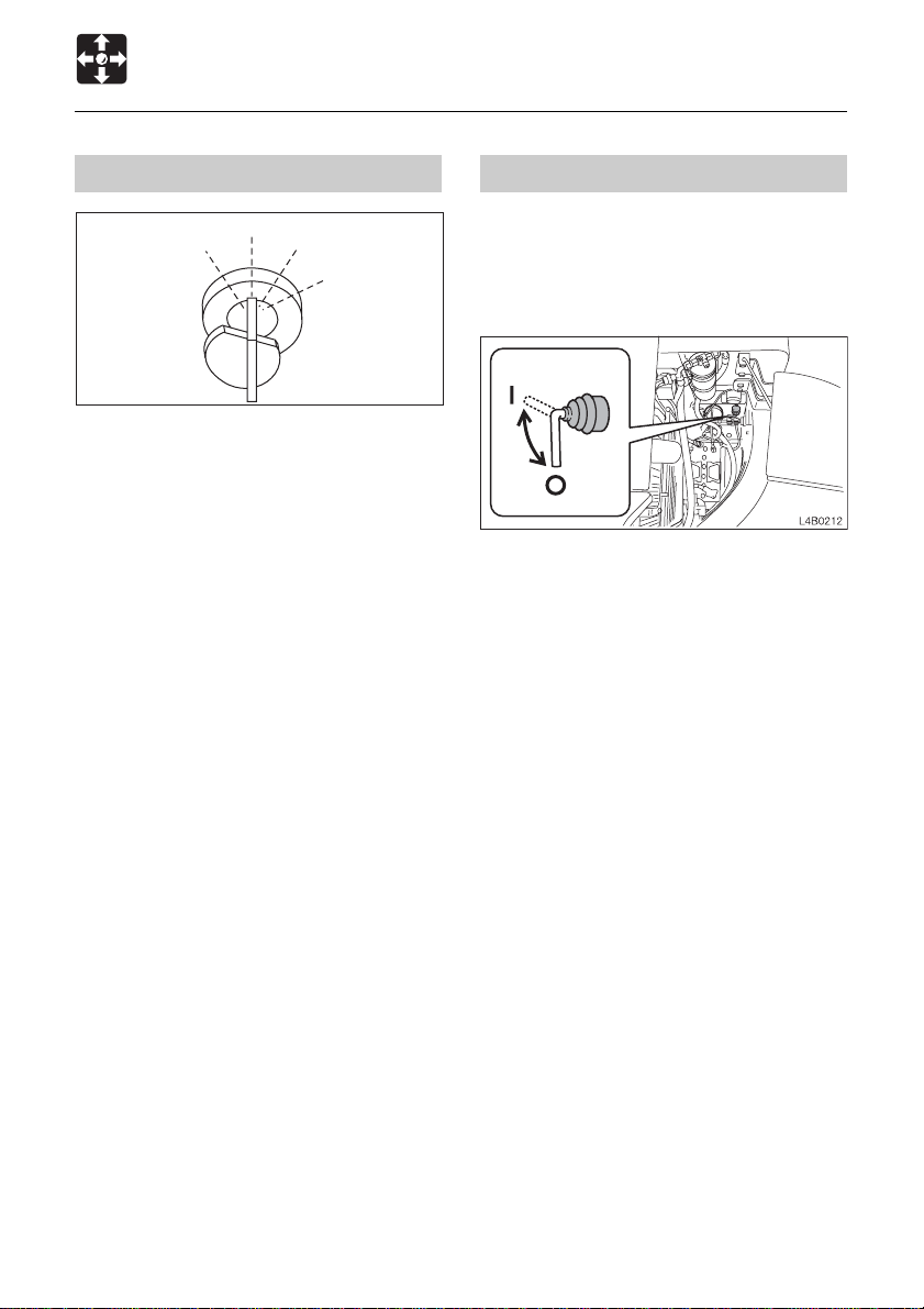
Battery Switch
IMPORTANT: Never set this switch to the
OFF (O) position while the engine is
running. Doing so might cause damage
to the electrical system.
1. Open the rear cover.
OFF (O) .... Switches off the electrical
circuit.Be sure to set this switch
to the OFF (O) position when
storing the machine for a long
period, or when performing
maintenance of the electrical
system.
ON ( I )...... Connects the electrical system.
Check that this switch is in the
ON ( I ) position before starting
the engine.
Supplement: Setting this switch to the OFF
(O) position will shut down all of the electrical
circuits and the memory of the radio preset
tuning buttons will be deleted.
48
Page 51

CONTROLS
Switches
Horn Button
Press the button on the right operating lever
to blow the horn.
Decel. Button
WARNING
Set the operating and travel levers to
neutral before operating the decel. button.
The machine’s operating speed will
change abruptly if the switch is operated
while the levers are engaged.
Automatic Decel. Button < TB180FR >
N0B019
Pressing this button to the ON position will
cause the lamp to light and will activate the
deceleration function. Use of the deceleration
button will not be possible at this time. After
about 4 seconds with the control levers set
to neutral, the engine speed will automatically
drop to Low idling to reduce fuel
consumption. Moving the control levers will
cause the speed to return to the original
engine speed.
Throttle Controller < TB180FR >
Press the button on the right operating lever
to lower the engine speed to low idling.
Press the button again to return to the engine
speed set with the throttle controler.
Supplement: The one-touch decelerator is
a device for lowering the engine speed and
reducing fuel consumption when little engine
output is required, for example when the
operating and travel levers are in neutral.
This controls the engine speed.
(A) .... Low idling
(B) .... Middle speed
(C) .... Maximum speed
49
Page 52

CONTROLS
Switches
Attachment Interference Switch
WARNING
¡¡
¡Failure to properly set the Attachment
¡¡
Interference Switch can result in
equipment damage, serious injury, or
death.
¡¡
¡Ensure that all buckets used in the
¡¡
standard position are no longer than a
standard bucket when measured from
pin to tooth.
The Attachment Interference Switch (AIS) is
automatically set to the M mode by the
interference Prevention System (IPS) when
the engine is started.
To use the minimal front radius feature, reset
the AIS to the M position then select the
appropriate attachment width (S.L or M).
< TB153FR >
S
Modes of Operation
< TB153FR >
S....... Standard bucket attachment less
than 635mm (24 inches) wide
L ....... Bucket attachment more than
635mm (24 inches) and less than
800mm (31 inches) wide
M ...... Bucket attachment more than
800mm (31 inches) wide or any other
approved attachment
< TB180FR >
S....... Standard bucket attachment less
than 750mm (30 inches) wide
L ....... Bucket attachment more than
750mm (30 inches) and less than
1000mm (40 inches) wide
M ...... Bucket attachment more than
1000mm (40 inches) wide or any
other approved attachment
Refer to page 82 “Attachment Interference
Switch / Interference Prevention System”.
L
M
J1B017
< TB180FR >
50
Page 53

CONTROLS
Switches
Travel Speed Switch
WARNING
When a load greater than a set value is
applied during 2nd speed (high speed)
travel, the speed will automatically slow
down by switching to 1st speed (low
speed). Thereafter, when the load
becomes lighter, the speed will increase
by returning to 2nd speed (high speed).
Exercise due caution since the travel
speed changes automatically.
Press this switch to set the travel speed to
2nd speed (high speed). Press again to
return to 1st speed (low speed).
First Auxiliary Hydraulic Switches
Slider Switch
(Proportional control)
Proportional control allows for slow-to-fast
movement of auxiliary functions.
Example: If you move the slider switch half
way, the auxiliary function will move at
approximately one-half speed.
Move this switch to control the flow of the oil
in the first auxiliary hydraulic lines.
Auxiliary Hydraulic Buttons
Press those buttons to control the flow of the
oil in the first auxiliary hydraulic lines.
¡Proportional control of the auxiliary
hydraulic circuit is not possible.
(A) .... Hydraulic oil flows to left auxiliary
line(a)
(B) .... Hydraulic oil flows to right auxiliary
line(b)
51
Page 54

CONTROLS
Switches
Light Switch
L3B028
When this switch is turned while the starter
switch is at ON, the lights turn on as follows :
O ...... Off
I ....... Meter light, front light and boom light
turn on.
Wiper Switch (Cab)
IMPORTANT: If no washer fluid is
discharged, do not operate the washer.
Doing so may damage the pump.
IMPORTANT: Operating the wiper with no
moisture on the windshield will scratch
the glass. Apply water or washer fluid
when operating the wiper.
IMPORTANT: In cold seasons, the wiper
blade may freeze to the glass. Operating
the wiper forcibly may damage the wiper
motor.
PUSH
L3B029
O ............ Off
I ............. Wiper operates.
PUSH ..... Washer fluid is squirted from the
nozzle while pressed, and stops
when released.
52
Page 55

CONTROLS
Levers and Pedals
Safety Lock Lever
WARNING
¡¡
¡Before leaving the operator’s seat,
¡¡
raise the safety lock lever to engage
the lock and stop the engine. If any
controls should be touched
accidentally when the safety lock lever
is lowered, the machine will move
suddenly, and cause serious injury or
death.
¡¡
¡< TB153FR > : Note that the dozer blade
¡¡
control is not locked, even when the
safety lock lever is set to the lock
position. Do not touch this control
accidentally .
¡¡
¡Be careful not to touch the operating
¡¡
levers when raising and lowering the
safety lock lever.
Operating Levers
WARNING
¡¡
¡Be careful to check which pattern of
¡¡
lever control arrangement you are
operating with before beginning
operations.
¡¡
¡The explanations in this manual are for
¡¡
the ISO pattern.
Use these levers to operate the boom, arm,
bucket and upperstructure (slew).
Refer to page 74 “Lever Pattern”.
Refer to page 84 “Operating the Working
Equipment”.
S2B015
This device is for locking the working
equipment, auxiliary hydraulic control,
slewing and traveling.
When the lever is raised, the lever stand
springs up and the lever is locked.
¡< TB153FR > : Note that the dozer blade
control is not locked, even when the safety
lock lever is set to the lock position. Do
not touch this control accidentally.
53
Page 56

CONTROLS
Levers and Pedals
Throttle Lever < TB153FR >
A
This controls the engine speed.
(A) .... Low idling
(B) .... Maximum speed
B
Blade Lever
D5B021E
Travel Levers
WARNING
Before operating the travel levers, check
to make sure that the dozer blade is to
the front of the operator’s seat. BE
AWARE that when the dozer blade is to
the rear of the operator’s seat, the travel
levers operate in the opposite direction
to when the dozer blade is in the front.
Use these to move forward and backward
and to change directions.
Refer to page 79 “Operating the Travel
Levers”.
Use this lever to operate the dozer blade.
(A) .... Blade up
(B) .... Blade down
Refer to page 85 “Operating the Dozer
Blade”.
54
Page 57

CONTROLS
Levers and Pedals
Offset Pedal
Use this pedal to operate the boom offset.
(A) .... Boom offset right
(B) .... Boom offset left
Refer to page 85 “Operating the Boom
Offset”.
Pedal Lock
WARNING
When not using the pedal, set the pedal
lock to the locked position. Stepping on
a pedal accidentally when it is not locked
may lead to unexpected accidents.
This device is for locking the offset pedal.
Set the pedal lock over the pedal to lock it.
55
Page 58

CONTROLS
Accessories
Heater (Cab)
WARNING
¡¡
¡Always be sure to allow sufficient
¡¡
ventilation.
¡¡
¡Do not place combustible or explosive
¡¡
objects near the air outlets.
Control panel
Fan Switch (1)
Use this switch to adjust the fan speed in
three steps.
OFF ........ Fan off
............ Low
............ Medium
............ High
Temperature Control Dial (2)
Use this dial to adjust the air temperature.
Counterclockwise
.......................... To lower the temperature
Clockwise ..... To increase the temperature
Supplement: No warm air is emitted if the
temperature of the engine coolant is low.
Airflow mode control dial (3)
Use this dial to select recirculation or fresh
air intake.
............... Recirculation
• To cool or heat the cab quickly
• When external air is dirty
CENTER.... 50% fresh air intake
• To ventilate while heating the cab slowly
............. Fresh air intake
• To remove fog from the windows
• To ventilate while heating the cab
Outlets
Move the louvers up and down or left and
right to adjust the air flow direction and
amount.
Supplement: Use the heater with care in
warm seasons. Coolant circulates in the
heater even when the heater switch is turned
off.
When the heater is no longer needed, stop
coolant circulation as follows :
IMPORTANT: Use the valve (1) either fully
open or fully closed.
Cooling water could leak when the valve
is set at a halfway position.
56
Page 59

CONTROLS
Accessories
< TB153FR >
< TB180FR >
1. Park on a flat surface and stop the engine.
2. Open the engine hood.
3. Turn the valve (1) clockwise until it stops
to close it.
Interior Light (Cab)
IMPORTANT: The battery capacity will
decrease if the interior light is left on for
long periods of time the engine stopped.
Turn the lamp off when leaving the
machine.
I
O
C4C024
O ...... Off
I ....... Lit
57
Page 60

CONTROLS
Accessories
Cigarette Lighter (Cab)
WARNING
¡¡
¡Do not leave the cigarette lighter’s
¡¡
knob pressed in. Doing so heats up the
lighter, and could be dangerous.
¡¡
¡If the knob does not pop out after 30
¡¡
seconds, it may be broken. Pull it out
by hand.
¡¡
¡Do not use other cigarette lighters, as
¡¡
they may get stuck.
¡¡
¡Only use applicable electric products
¡¡
with this socket.
¡¡
¡Do not touch metal parts of the lighter .
¡¡
Doing so could cause burns.
This is the cigarette lighter and internal power
supply socket.
When using the wiper and this socket
simultaneously, be careful not to exceed
12V / 10A.
Ashtray (Cab)
WARNING
¡¡
¡Be sure to extinguish cigarettes and
¡¡
matches completely before putting
them in the ashtray, and always close
the ashtray afterwards.
¡¡
¡Do not overfill the ashtray with
¡¡
cigarette butts or put in paper or other
easily burnable objects. Doing so could
lead to fire.
Pull the ashtray out towards you to use it.
To clean, press the ash discharge button (1)
and pull out the ashtray.
1. Press the lighter in.
2. Release the lighter and wait for it to pop
out. The lighter pops out automatically
when the heater becomes red.
3. Once the lighter pops out, pull it out.
58
Page 61

CONTROLS
Accessories
External Power Sockets (for EU)
WARNING
Only use applicable electric products with
these sockets.
1
L2C0071
for Beacon
1
N0C008
Use these sockets as an external power
supply. When using these sockets, be
careful not to exceed 12V / 10A.
To use, raise the cap (1).
Applicable plug: BOSCH 0352321007
59
Page 62

CONTROLS
Accessories
Radio
Operating precautions
¡To ensure safe operation of the machine, always be sure to keep the volume of the radio
down to a level where you can easily hear sounds from outside the machine.
¡Do not keep the radio playing for long periods of time with the engine stopped. Doing so
will drain the battery of its charge and make it difficult or impossible to restart the engine.
¡Be careful not to allow water or other liquids to come into contact with the radio . Doing so
may result in it being rendered inoperable.
¡Be careful not to insert cassette tapes backward. Doing so may damage the cassette
player. Insert tapes with the head of the tape facing to the right.
¡Always remove the cassette from the player when not in use.
Names of components
16 153 6 7 8
11
TRE
LOUD DISP
SEEKDNSEEK
M
H
UP
9 5 4 13 14
BASS
12 10
2
PS/AS
BAND
VOL
1
(1) (2) Power switch / volume control knob
Turn this knob clockwise. The “click” sound
indicates that the power supply is turned on.
Further turning increases the speaker
volume. If a tape is loaded in the radio, eject
the tape to switch to the radio.
KRH–M867
AUTO REVERSE CASSETTE STEREO RECEIVER
MTL LOUD ST
FM1
FM2
AM
DC12V/24V
(3) Tone control
¡Bass control knob
¡Treble control knob
1
2
3
5
4
METAL
6
L2C001
60
Page 63

CONTROLS
Accessories
(4) Program indicators
Indicates tape direction. When s lamp is on.
Upper side of a tape is playback, t indicates
playback of lower side.
(5) Display
G
D FBE G
MTL LOUD ST
A C
FM1
FM2
AM
L2C002
(A) Band
(B) Time / Frequency
(C) Memory channel (1–6)
(D) Metal
(E) FM Stereo
(F) Loudness
(G)T ape direction
(6) Eject button
Push this button to eject the cassette tape.
¡To change over to radio while listening to
a cassette tape, press the EJECT button
to stop the tape and the system will
automatically change over to radio.
(7) Cassette door
Insert the cassette tape with the exposed
magnetic tape side facing to the right.
¡Simply insert a tape to change over to the
cassette tape mode while listening to the
radio.
(8) Fast-forward / rewind /
program changeover button
Fast-forward
MTL LOUD ST
FM1
FM2
AM
L2C003
Fast-rewind / Stop
MTL LOUD ST
FM1
FM2
AM
L2C004
To fast-forward the tape, push the button
matching the direction of program indication
and to rewind, push the other button. T o stop
fast-forwarding or rewinding, lightly press the
button which is not locked to cancel the
operation. The system will then start playing
the tape again normally.
61
Page 64

CONTROLS
Accessories
KRH–M867
AUTO REVERSE CASSETTE STEREO RECEIVER
FM1
FM2
AM
MTL LOUD ST
M
H
To change the program, press the fastforward and rewind buttons simultaneously.
The direction of tape feed will reverse.
¡When the tape ends in one direction, the
system automatically reverses the tape
and plays the other side.
¡To stop fast-forwarding or rewinding, lightly
touch the unlocked key. This frees the
locked key and normal playing resumes.
(9) Tuner switch (Manual tuning)
Pressing the
raises the receiving frequency. Pressing the
shaped TUNER button lowers the
receiving frequency similarly. Pressing either
of these buttons continuously shifts the
receiving frequency continuously.
(10) SEEK switch
Pressing the “SEEK” button shifts the
receiving frequency in the higher or lower
frequency direction before automatically
stopping at a position where a station is
picked up.
(11) LOUD switch
This button is used to operate the system at
a lower sound volume but with enhanced
bass and treble sound. (“LOUD” indication
appears on the display .)
DC12V/24V
142
METAL
3
6
5
L2C005
shaped TUNER button
(12) Band select switch
Pressing the “BAND” button changes over
between FM1, FM2 and AM (MW) bands.
The display indicates the receiving band
name and frequency.
(13) Metal switch
Press the “MTL” (5) button before playing a
metal or CrO
tape.
2
The “MTL” indication appears on the display.
(14) Preset switch keys
One station each in the FM1, FM2 and
AM(MW) bands, respectively, can be preset
for each of these preset keys.
When listening to a preset station, select
either of the AM, FM1,FM2 bands using the
band select switch, then simply press the
number key corresponding to the preset
selected station.
The system can memorize 6 stations in AM
band and 12 stations in FM bands (FM1: 6
stations and FM2: 6 stations).
Manual Memory
Use manual tuning button or seek tuning
button to choose a radio station if a
broadcasting station is wanted to be
recorded. For 2 seconds press 1–6 preset
key when the indication of frequency has
already shown and the frequency is
recorded. Flash stops and channel starts
functioning.
¡If the main power supply is interrupted,
such as when exchanging machine
battery, all presettings will be erased.
Repeat the presetting procedure in
such case.
62
Page 65

CONTROLS
A
Accessories
(15) DISP (Time / Frequency) button
This system is equipped with a clock which
can show the accurate time. Even if the radio
is off, the clock still shows the time.
(16) PS / AS switch
Push this button 2 sec below will
automatically operates to show the
memorized station from 1 to 6. The signal
scaning start by pushing this button
momentarily . When a station is received the
scaning automatically stops there for 5
seconds FLASHLY and then resumes
scaning. As soon as the desired station is
found, press the this button again.
If you will auto memory push this button over
5 sec so initiates a scan of the band. Station
frequencies are either stored in order of low
of frequency for FM, or in sequence for AM,
starting from preset channel 1. If all of the
preset channels have not been filled up after
one scan, the remaining preset channels are
left unchanged, and channel 1 is recalled.
Channel 8 flashes during A.
¡¡
¡Set the time
¡¡
TRE
S LOUD DISP
SEEKDNSEEK
D
BASS
VOL
UP
PS/AS
M
H
BAND
TRE
LOUD DISP
SEEKDNSEEK
M
H
UP
L2C006
After pressing DISP button, press tuner
button
tuner button
or to correct the time. Press
to set the “hour” and tuner
button for setting the “minute”. Set the
time when the time is shown.
63
Page 66

CONTROLS
Accessories
First Auxiliary Hydraulic Lines
WARNING
Oil may spurt out if caps or filters are
removed or pipes disconnected before
releasing the pressure in the hydraulic
system.
¡¡
¡When disconnecting hoses, release the
¡¡
internal pressure before removing.
These lines deliver the hydraulic oil
necessary for operating a hydraulic breaker,
crusher or other attachments.
< TB153FR >
O
S
b
a
J1C002
< TB180FR >
2. Remove the plugs.
3. Connect the attachment hydraulic lines to
ports (a) and (b).
When fitted with a hydraulic breaker,
connect the return circuit to port (b) and
the supply circuit to port (a).
4. Open the stop valves.
When fitted with a hydraulic breaker, open
the selector valve (1).
Refer to pege 65 “Selector valve”.
5. When connecting is complete, purge air
from the hydraulic lines.
a. Start and run the engine at low idle with
no load for 10 minutes.
b. With the engine running at low idle
operate the auxiliary hydraulic switches
repeatedly (approx. 10 times) to purge
air from the hydraulic lines.
c. Stop the engine and wait for more than
5 minutes until bubbles escape from the
hydraulic oil in the tank.
IMPORTANT: Follow the procedures for
purging air as instructed by the
attachment manufacturer if specified to
do so.
Stop valve..... S : Closed O : Open
Connecting the Hydraulic Circuits
To connect the attachment hydraulic lines,
use the following procedures:
1. Release the pressure remaining in the
lines then close the stop valve.
Refer to “Releasing the residual pressure”.
6. Check for leaks.
Disconnecting the hydraulic circuits
1. Release the pressure remaining in the
lines then close the stop valve.
Refer to “Releasing the residual pressure”.
2. Disconnect the lines from ports (a) and
(b).
3. Install the plugs.
Releasing the residual pressure
After using the auxilliary hydraulic circuits,
pressure remains in the circuits. This is called
the residual pressure. Release this residual
pressure before disconnecting the lines.
64
Page 67

CONTROLS
Accessories
1. Start the engine and press the auxiliary
hydraulic button (B).
(The residual pressure is released from
the (a) port line, and pressure is generated
in the (b) port.)
2. Stop the engine and open the selector
valve (1) on the machine body .
(The residual pressure is released from
the (b) port line.)
When equipped with accumulator (option) :
Refer to page 204 “Releasing the residual
pressure”.
Selector valve
O: Open .......When using a hydraulic
breaker (1-way flow)
S: Closed.....When using a reversible
attachment (2-way flow)
Change the direction of the hydraulic oil flow
by opening or closing the selector valve on
the machine body .
65
Page 68

66
Page 69

OPERATION
Before Starting Operation ......................... 68
Starting and Stopping the Engine
<TB153FR>.............................................70
Starting and Stopping the Engine
<TB180FR>.............................................72
Machine Operation.....................................74
Operating Procedures ...............................88
Parking the Machine ..................................96
Handling in Cold Weather..........................97
Handling Rubber Crawlers ........................ 98
67
Page 70

OPERATION
Before Starting Operation
Mounting and Dismounting
WARNING
¡¡
¡Do not jump on or off the machine.
¡¡
Never attempt to mount or dismount a
moving machine.
¡¡
¡When mounting and dismounting the
¡¡
cab, first open the door fully to the
locked position and check that it does
not move. (For machines with cabs)
¡¡
¡Always face the access system and
¡¡
maintain a three point contact with the
recommended handrails and steps
while getting on and off the machine.
Keep steps and platform clean.
¡¡
¡Never use the safety lock lever or
¡¡
control levers as hand holds.
Walk-Around Inspection
Perform the walk-around inspections once
a day before starting the engine the first time
that day.
Perform the inspections as described under
“Maintenance - Walk-Around Inspection”
(pages 118 and 119).
Daily Inspection
Perform the daily inspections once a day
before starting the engine the first time that
day.
Perform the inspections as described under
“Maintenance - Daily Inspection” (pages
120 to 124).
68
Page 71

OPERATION
Before Starting Operation
Before Starting the Engine
1. Adjust the seat for a comfortable operating
position.
2. Fasten the seat belt.
S2B015
3. Check that the safety lock lever is in the
locked position.
¡All the warning lamps flash and an
alarm is sounded for 2 seconds. The
meters also start functioning. After 2
seconds, only the battery charge
warning lamp (4) and engine oil
pressure / coolant level warning lamp
(2) flash, and the other lamps turn off.
¡< TB180FR > : Check that the decel. lamp
(8) is lit.
¡Turn the light switch to check that the
boom light, front light and meter light
turn on.
¡Check the fuel level.
4. Check that all the levers and pedals are
in the neutral position.
OFF
PREHEAT
ON
START
E4D002
5. Insert the key into the starter switch, turn
it to the ON position, then perform the
following inspection :
If a lamp does not light or the alarm is not
sounded, the bulb may be burnt out or a wire
may be damaged. Contact a T akeuchi sales
or service outlet for repairs.
69
Page 72

OPERATION
Starting and Stopping the Engine < TB153FR >
Starting the Engine
WARNING
¡¡
¡Clear the area of all persons.
¡¡
¡¡
¡Sound horn to alert everyone around
¡¡
the machine.
IMPORTANT: Do not ru n the sta rter mot or
for more than 15 consecutive seconds. If
the engine fails to start, wait for 30
seconds to protect the battery, and then
try again to start the engine.
Normal Starting
D5D014E
1. Pull the throttle lever to the middle position.
OFF
PREHEAT
ON
START
E4D005
Starting in Cold Weather
D5D014E
1. Pull the throttle lever to the middle position.
OFF
PREHEAT
ON
START
E4D060
2. Turn the key to the PREHEA T position and
hold it there while the glow lamp is lit (about
15 seconds).
3. After the glow lamp turns off, then turn it
to the STAR T position and start the engine.
4. Once the engine starts, release the key.
The key automatically returns to the ON
position.
5. Check that the warning lamps are off.
6. Return the throttle lever and warm up the
engine.
Refer to page 71 “Warming Up the
Engine”.
2. Turn the key to the START position and
start the engine.
3. Once the engine starts, release the key.
The key automatically returns to the ON
position.
4. Check that the warning lamps are off.
5. Return the throttle lever and warm up the
engine.
Refer to page 71 “Warming Up the
Engine”.
70
Page 73

OPERATION
Starting and Stopping the Engine < TB153FR >
Warming Up the Engine
IMPORT ANT: Avoid racing the engine
until it is warmed up.
Do not warm up the engine for long
periods of time (20 minutes or more).
D5D015E
1. Return the throttle lever, then idle the
engine and run it for about 5 minutes with
no load.
Stopping the Engine
IMPORTANT: Do not stop the engine
suddenly when operating with heavy
loads or at maximum speed. Doing so
may cause the engine to overheat or
seize. Never bring the engine to a sudden
stop except in the case of a true
emergency.
D5D016E
1. Press the decel. button or return the
throttle lever.
2. Idle the engine for about 5 minutes to
gradually let it cool.
OFF
PREHEAT
ON
START
3. Turn the key to the OFF position to stop
the engine.
71
E4D007
Page 74

OPERATION
Starting and Stopping the Engine < TB180FR >
Starting the Engine
WARNING
¡¡
¡Clear the area of all persons.
¡¡
¡¡
¡Sound horn to alert everyone around
¡¡
the machine.
IMPORTANT: Do not ru n the sta rter mot or
for more than 15 consecutive seconds. If
the engine fails to start, wait for 30
seconds to protect the battery, and then
try again to start the engine.
Normal Starting
OFF
PREHEAT
1. Turn the key to the START position and
start the engine.
2. Once the engine starts, release the key.
The key automatically returns to the ON
position.
3. Check that the warning lamps are off.
4. Warm up the engine :
Refer to page 73 “Warming Up the
Engine”.
ON
START
E4D005
Starting in Cold Weather
OFF
PREHEAT
ON
START
E4D060
1. Turn the key to the PREHEA T position and
hold it there while the glow lamp (6) is lit
(about 15 seconds).
2. After the glow lamp (6) turns off, then turn
it to the START position and start the
engine.
3. Once the engine starts, release the key.
The key automatically returns to the ON
position.
4. Check that the warning lamps are off.
5. Warm up the engine :
Refer to page 73 “Warming Up the
Engine”.
72
Page 75

OPERATION
Starting and Stopping the Engine < TB180FR >
Warming Up the Engine
IMPORT ANT: Avoid racing the engine
until it is warmed up.
Do not warm up the engine for long
periods of time (20 minutes or more).
1. Idle the engine and run it for about 5
minutes with no load.
2. Press the decel. button to return to the
engine speed set with the throttle
controller.
Stopping the Engine
IMPORTANT: Do not stop the engine
suddenly when operating with heavy
loads or at maximum speed. Doing so
may cause the engine to overheat or
seize. Never bring the engine to a sudden
stop except in the case of a true
emergency.
1. Press the decel. button or return the
throttle controller.
2. Idle the engine for about 5 minutes to
gradually let it cool.
OFF
PREHEAT
ON
START
E4D007
3. Turn the key to the OFF position to stop
the engine.
73
Page 76

OPERATION
Machine Operation
Lever Pattern (ISO Pattern)
WARNING
¡¡
¡Be careful to check which pattern of lever control arrangement you are operating
¡¡
with before beginning operations.
¡¡
¡The explanations in this manual are for the ISO pattern.
¡¡
Left Crawler Forward
Left Crawler Reverse
Arm Out
Arm In
Upperstructure Left Slew
Upperstructure Right Slew
Boom Offset Left
Boom Offset Right
Right Crawler Forward
Right Crawler Reverse
Boom Lower
Boom Raise
Bucket Load
Bucket Dump
Dozer Blade Lower
Dozer Blade Raise
74
Page 77

OPERATION
Machine Operation
Lever Pattern (JCB Pattern)
WARNING
¡¡
¡Be careful to check which pattern of lever control arrangement you are operating
¡¡
with before beginning operations.
¡¡
¡The explanations in this manual are for the ISO pattern.
¡¡
Left Crawler Forward
Left Crawler Reverse
Boom Lower
Boom Raise
Upperstructure Left Slew
Upperstructure Right Slew
Boom Offset Left
Boom Offset Right
Right Crawler Forward
Right Crawler Reverse
Arm Out
Arm In
Bucket Load
Bucket Dump
Dozer Blade Lower
Dozer Blade Raise
75
Page 78

OPERATION
Machine Operation
Warming Up the Machine (Hydraulic Oil)
WARNING
Operating the working equipment without
warming up the machine (hydraulic oil)
is dangerous, as response will be slow
and the equipment may move in
unexpected ways. Be sure to sufficiently
warm up the machine.
IMPORTANT: Do not operate the levers
suddenly when the hydraulic oil
temperature is below 20
proper hydraulic oil temperature during
operation is 50 to 80°C (122 to 176°F), but
if operations must be performed at lower
temperatures, heat up the hydraulic oil
to at least 20
°C (68°F).
Normal Warm-up
< TB153FR >
°C (68°F). The
1. Turn the throttle controller to the middle
position (B).
2. Run the engine at medium speed for about
5 minutes with no load.
S2D007
3. Fully lower the safety lock lever to
disengage the lock and raise the pedal
lock to disengage the lock.
E4D009
D5D014E
1. Pull the throttle lever to the middle position.
< TB180FR >
4. Lift the bucket from the ground.
5. Extend and retract each of the cylinders
several times with no load.
6. Slew slowly left and right several times.
76
Page 79

OPERATION
Machine Operation
7. Travel slowly forward and backward
several times.
Warming Up in Cold Weather
1. Perform the normal warm-up procedure.
E4D011
Inspection After Warm-up
After warming up the engine and hydraulic
oil, perform the checks and inspections
described below, and repair if there is a
problem.
1. Check that the warning lamps and meters
are as follows :
• Are all the warning lamps off?
• Is the water temperature gauge’s needle
within the green range?
2. Check that there are no irregularities in
the exhaust color, sound and vibrations.
2. Set the bucket cylinder at the stroke end
and keep it there.
Do not do this for more than 30 seconds.
3. Repeat step 2 until the bucket operating
speed is normal.
S2B015
3. Raise the safety lock lever to engage the
lock and check that the operating, offset,
dozer blade and travel levers are locked.
¡< TB153FR >: Note that the dozer blade
control is not locked, even when the safety
lock lever is set to the lock position.
4. Perform the inspection operations
described below and check that the
bucket, arm and boom do not touch the
cab when the boom or bucket is moved
near the cab and stops automatically.
77
Page 80

OPERATION
Machine Operation
1
L2D009
(1) Offset the boom to the front of the
operator’s seat and move the boom near
the cab.
Offset the boom to the right and move
the bucket near the cab.
2 3
L2D010
(2) Offset the boom fully to the right and
check that it can be set to the maximum
rear inclination.
(3) Offset to the left in the posture in (2)
above
Operation when the boom has stopped
automatically
1. If the boom has stopped while rising:
Operate the boom downward.
2. If the boom has stopped while offsetting
to the left:
a. Operate the boom downward to move
it outside the automatic stop range.
b. Offset to the left.
Offsetting to the right is possible
regardless of the boom’s posture.
78
Page 81

OPERATION
Machine Operation
Operating the Travel Levers
WARNING
¡¡
¡Never allow anyone to enter the
¡¡
slewing (swing) radius and machine
path.
¡¡
¡Signal your intention to move by
¡¡
sounding the horn.
¡¡
¡There are blind spots to the rear of the
¡¡
machine.
If necessary,swing the cab around
before backing up to check that the
area is safe and clear.
¡¡
¡Before operating the travel levers,
¡¡
check to make sure that the dozer blade
is to the front of the operator’s seat.
BE AWARE that when the dozer blade
is to the rear of the operator’s seat, the
travel levers operate in the opposite
direction to when the dozer blade is in
the front.
¡¡
¡Remove any obstacles in the
¡¡
machine’s path.
Traveling Forward and Backward
1. Increase the engine speed.
S2D007
2. Fully lower the safety lock lever to
disengage the lock.
30~40cm
E4D014
3. Fold the hoe attachment and lower it to
30 to 40 cm(12 to 16 in.) above the ground.
4. Lift the dozer blade.
5. Operate the left and right travel levers as
described below.
79
Page 82

OPERATION
Machine Operation
Traveling in 2nd (High) Speed
Neutral Neutral
E4D015
When the dozer blade is in front of the
operator’s seat :
aTo move forward :
Tilt the levers forward.
eTo move backward :
Tilt the levers backward.
Neutral Neutral
E4D016
When the dozer blade is behind the
operator’s seat :
aTo move forward :
Tilt the levers backward.
eTo move backward :
Tilt the levers forward.
WARNING
When a load greater than a set value is
applied during 2nd speed (high speed)
travel, the speed will automatically slow
down by switching to 1st speed (low
speed). Thereafter, when the load
becomes lighter, the speed will increase
by returning to 2nd speed (high speed).
Exercise due caution since the travel
speed changes automatically.
Press the travel speed switch on the right
travel lever to switch to 2nd (high) speed,
and press it again to return to 1st speed (low
speed).
Pivot Turn
Neutral
Turning to the left when stopped :
aTo turn forward to the left :
Tilt the right lever forward.
eTo turn backward to the left :
Tilt the right lever backward.
To turn to the right, operate the left lever in
the same way.
80
E4D017
Page 83

OPERATION
Machine Operation
Neutral
E4D018
Turning to the left while traveling :
aTo turn left while traveling forward :
Set the left lever to neutral.
eTo turn left while traveling backward :
Set the left lever to neutral.
To turn to the right while traveling, operate
the right lever in the same way .
Spin T urn
Neutral
Stopping Travel
WARNING
¡¡
¡Park the machine on firm, level ground
¡¡
and apply the parking device. If you
must park on a slope or incline, block
the machine securely to prevent
movement.
¡¡
¡If any controls should be touched
¡¡
accidentally when the safety lock lever
is lowered, the machine will move
suddenly, and cause serious injury or
death.
¡¡
¡< TB153FR > : Note that the dozer blade
¡¡
control is not locked, even when the
safety lock lever is set to the lock
position. Do not touch this control
accidentally .
CAUTION
Never bring the machine to a sudden stop
except in the case of a true emergency.
Stop as gently as possible.
aTo spin left :
Tilt the left lever backward and the right
lever forward.
eTo spin right :
Tilt the right lever backward and the left
lever forward.
E4D019
Neutral
Neutral
1. Slowly set the left and right travel levers
to the neutral position. The machine stops.
81
E4D020
Page 84

OPERATION
Machine Operation
Attachment Interference Switch / Interference Prevention System
WARNING
¡¡
¡All attachments other than a bucket
¡¡
should be used with the AIS set to the
M mode.
¡¡
¡Ensure that all buckets used in the
¡¡
standard position are no longer than a
standard bucket when measured from
pin to tooth.
¡¡
¡Failure to properly set the Attachment
¡¡
Interference Switch can result in
equipment damage, serious injury, or
death.
¡¡
¡Do not disassemble or damage the
¡¡
sensors installed on the boom and
main body. Doing so may cause the
Interference Prevention System to
malfunction. If there is a problem,
contact a Takeuchi sales or service
outlet for inspection or repair.
Sensors
The Attachment Interference Switch (AIS)
allows the operator to select the attachment
size used on the excavator. The Interference
Prevention System uses the operator’s AIS
selection to limit the movement of the boom
(raising, lowering, and offsetting) to prevent
the cab from being struck by the boom,
attachment, or the material being handled.
The Interference Prevention System (IPS)
is automatically set to the M mode when the
engine is started to provide the maximum
operator protection.
< TB153FR >
< TB180FR >
J1B018
¡¡
¡The interference prevention system
¡¡
may not function properly if
attachments other than Takeuchi
approved attachments are installed.
Do not install other non-approved
attachments.
82
S
L
M
J1B017
Page 85

OPERATION
Machine Operation
To properly set the AIS :
Reset the AIS to the M position
Select the appropriate attachment width
< TB153FR >
S....... Standard bucket attachment less
than 635mm (24 inches) wide
L ....... Bucket attachment more than
635mm (24 inches) and less than
800mm (31 inches) wide
M ...... Bucket attachment more than
800mm (31 inches) wide or any other
approved attachment
< TB180FR >
S....... Standard bucket attachment less
than 750mm (30 inches) wide
L ....... Bucket attachment more than
750mm (30 inches) and less than
1000mm (40 inches) wide
M ...... Bucket attachment more than
1000mm (40 inches) wide or any
other approved attachment
Operate excavator
The minimal front radius feature is only
available for the standard bucket
attachment 635mm (24 inches) TB153FR
/ 750mm (30 inches) TB180FR or smaller .
83
Page 86

OPERATION
Machine Operation
Operating the Working Equipment
WARNING
¡¡
¡Be careful to check which pattern of
¡¡
lever control arrangement you are
operating with before beginning
operations.
¡¡
¡The explanations in this manual are for
¡¡
the ISO pattern.
Use the right operating lever to operate the
boom and bucket.
Use the left operating lever to operate the
arm and for slewing.
Return the operating levers to the neutral
position to stop the hoe attachments.
1. Fully lower the safety lock lever to
disengage the lock.
2. Raise the pedal lock to disengage the lock.
E4D021
aTo slew left :
Tilt the left operating lever to the left.
eTo slew right :
Tilt the left operating lever to the right.
Operating the Boom
E4D022
aTo lower the boom :
Tilt the right operating lever forward.
eTo raise the boom :
Tilt the right operating lever backward.
Operating the Arm
Slewing
WARNING
Check the surrounding area for safety
before slewing.
E4D023
aTo contract the arm :
Tilt the left operating lever backward.
eTo extend the arm :
Tilt the left operating lever forward.
84
Page 87

OPERATION
Machine Operation
Operating the Bucket
aTo dig :
Tilt the right operating lever to the left.
eTo dump :
Tilt the right operating lever to the right.
Operating the Boom Offset
E4D024
aTo offset left :
Press the left side of the pedal.
eTo offset right :
Press the right side of the pedal.
Operating the Dozer Blade
aTo lower the dozer blade :
Tilt the lever forward.
eTo raise the dozer blade :
Tilt the lever backward.
L2D0061
E4D026
85
Page 88

OPERATION
Machine Operation
Operating the First Auxiliary Hydraulics
Use this to operate a breaker, crusher or
other attachment.
Two methods of operation are permitted:
operation with the auxiliary hydraulic buttons
and operation with the slider switch
(proportional control).
< TB153FR >
O
S
b
a
J1C002
< TB180FR >
Operating With the Slider Switch
(Proportional Control)
aTo deliver hydraulic oil to port (a):
Move the switch to the left (A).
eTo deliver hydraulic oil to port (b):
Move the switch to the right (B).
Operating With the Auxiliary Hydraulic
Buttons
aTo deliver hydraulic oil to port (a):
Press (A).
eTo deliver hydraulic oil to port (b):
Press (B).
86
Page 89

MEMO
87
Page 90

OPERATION
Operating Procedures
Prohibited Operations
WARNING
¡¡
¡Do not operate on base rock (hard or
¡¡
soft).
¡¡
¡Do not slew (swing) while traveling. If
¡¡
you must operate the hoe attachment
while traveling, operate at speeds slow
enough so you have complete control
at all times.
Do not perform breaking or leveling
operations using slew force
E4D029
Do not break down walls or level ground
using slew force. Also, do not dig the bucket
teeth into the ground during slewing. Doing
so will damage the hoe attachment.
Be Gentle on the Hydraulic Cylinders
E4D031
Do not extend the hydraulic cylinders to the
stroke ends. Operate them with leeway.
Do not support the machine body with the
hoe attachment as it is lowering with the arm
cylinder fully extended. Doing so
concentrates the load on the arm cylinder
and could damage the arm cylinder.
Do not Dig while Traveling
E4D030
Do not dig the bucket into the ground and
use the traveling force to dig.
Do not Drive Piles with the Bucket or Dig
with it Using Shock Force
E4D032
Doing so will shorten the service life of the
hoe attachment. Use hydraulic force to dig.
88
Page 91

OPERATION
Operating Procedures
Do not Perform Operations Using the
Machine’s Dropping Force
E4D033
Putting excessive strain on the machine will
shorten its service life. Use the hydraulic
force of the cylinders and always dig with
shallow, long strokes.
Digging Base Rock
Caution on Exposing the Dozer Blade to
Shocks
E4D040
Hitting the dozer blade against rocks, etc.,
could damage the dozer blade or the blade
cylinder.
Caution on Folding the Hoe Attachment
E4D041
Be careful not to hit the bucket or dozer blade
when folding the hoe attachment.
E4D034
For hard base rock, break the rock up into
small pieces with a breaker, etc., before
digging. This prevents damage to the
machine and is thus more economical in the
end.
Do not use the Dozer Blade as an Outrigger
N0D009
89
Page 92

OPERATION
Operating Procedures
Pay Attention to the Dozer Blade when
Digging
E4D0431
When digging deeply with the dozer blade
positioned at the front, be careful that the
boom cylinder and bucket do not hit the dozer
blade.
Operate with the dozer blade at the rear
whenever possible.
Caution on Digging Down with the Dozer
Blade
E4D044
This dozer blade is designed for simple earth
pushing. Do not dig down deeply with the
dozer blade. Doing so could damage the
dozer blade and lower body.
90
Page 93

OPERATION
Operating Procedures
Cautions on Operating
Cautions on Traveling
E4A040
Traveling over obstacles (rocks, stumps, etc.)
may subject the body to strong shocks and
result in damage. Avoid traveling over
obstacles whenever possible. If you must do
so, keep the hoe attachment near the ground,
travel at low speed, and go over the obstacle
at the center of the crawler.
Cautions on Traveling in 2nd (High)
Speed
E4D037
On uneven ground, travel at low speed and
avoid accelerating, stopping or changing
directions abruptly.
Also, when traveling in 2nd speed, do so with
the dozer blade at the front.
Cautions on Use in Water
E4D038
If you leave water at a sharp angle, the rear
of the machine may be submerged, exposing
the radiator fan to water and damaging them.
Do not let the rear of the machine get
submerged.
1
E4D039
¡Allowable water depth
In water, only use the machine up to a
depth at which the water comes up to the
middle of the carrier roller (1).
¡When greasing places used under water
for long periods of time, apply enough
grease so that the old grease is expelled.
¡Never submerge the slew bearing or main
body in water or sand. If the slew bearing
or main body should get submerged,
contact a Takeuchi sales or service outlet
for inspection.
91
Page 94

OPERATION
Operating Procedures
Cautions on Traveling on Slopes
WARNING
¡¡
¡Never exceed the machine’s stability
¡¡
capabilities (maximum gradeability – 30°,
lateral tipping angle – 15°). Also note
that when actual working area
conditions are poor the machine’s
stability capabilities may be lower.
¡¡
¡When traveling on slopes or grades,
¡¡
lower the bucket to a height of 20 to 30
cm (8 to 12 in.) off the ground. In
emergencies, lower the bucket to the
ground and stop the machine.
¡¡
¡When traveling on slopes or grades,
¡¡
move slowly in first gear (low speed).
¡¡
¡Do not travel down slopes in reverse.
¡¡
¡¡
¡Do not change directions or cross
¡¡
slopes sideways. First return to a flat
surface then redirect the machine.
¡¡
¡On grass, dead leaves, wet metal or
¡¡
frozen surfaces, the machine may slide
sideways even on very gentle slopes.
Make sure the machine never faces
sideways with respect to the slope.
Traveling Posture
Traveling up slopes
When traveling up slopes at an angle of 15°
or greater, travel in the posture shown in the
diagram above.
Traveling down slopes
When traveling down slopes at an angle of
15° or greater, lower the engine speed and
travel in the posture shown in the diagram
above.
Braking when traveling down slopes
Braking
When traveling down slopes, the brakes are
applied automatically when the travel levers
are returned to the neutral position.
92
D5D028E
Page 95

OPERATION
Operating Procedures
If the crawlers slip
Climbing
E4D046
If the crawlers slip while traveling up a slope,
use the pulling force of the arm to climb the
slope.
If the engine stops
Descending
D5D029E
If the engine stops when traveling down a
slope, set the travel levers to the neutral
position, stop the machine, then start the
engine.
Do not open the door while traveling on
slopes
E4D048
Opening the door while traveling on slopes
is dangerous, as the force required to open
and close the door changes abruptly . Always
keep the door closed when traveling on
slopes.
93
Page 96

OPERATION
Operating Procedures
Getting Out of Mud
If the machine gets stuck in mud, use the
procedure below to get it out.
If one crawler is stuck
1. Slew the bucket to the side which is stuck.
2. Set the arm and boom to an angle of 90
to 110 °.
3. Press the bottom of the bucket (not the
teeth) against the ground.
4. Place a plank, etc., under the lifted crawler.
5. Lift the bucket and slowly move out of the
mud.
If both crawlers are stuck
1. Perform steps 1 to 4 above for both
crawlers.
2. Dig the bucket into the ground in front of
the machine.
3. Pull with the arm and travel forward
simultaneously to slowly move out of the
mud.
Operations Possible with this Machine
Excavating
80 ~120
E4D0501
1. Set the dozer blade on the side opposite
the side you want to dig on.
2. Use the arm and bucket and dig with
shallow, long strokes. The digging force
is strongest when the boom and arm angle
is 80 to 120°. Use this angle for effective
digging.
Digging Ditches
E4D051
Mount a bucket suited for digging ditches and
set the crawlers parallel to the ditch to be
dug for greater efficiency.
When digging wide ditches, dig the sides first,
the center later.
94
Page 97

OPERATION
Operating Procedures
Digging Side Ditches
60°
75°
E4D052
Use the boom swing function to dig side
ditches as shown in the diagram.
Loading
When loading dirt in a truck, starting from
the back of the truck’s bed makes for easier
loading and increases the amount of dirt that
can be loaded.
Also, use a small slewing angle for greater
efficiency.
3. Once the mound is low, remove the dirt
from the top. If the load on the body is too
heavy, adjust by raising or lowering the
dozer blade.
Leveling
E4D053
1. Bring the hoe attachment close to the
body .
2. Gradually remove the dirt from the side of
the mound.
95
Page 98

OPERATION
Parking the Machine
Parking
WARNING
E3A4901
¡¡
¡Park the machine on firm, level ground
¡¡
and apply the parking device.
¡¡
¡Before leaving the operator’s seat,
¡¡
raise the safety lock lever to engage
the lock and stop the engine. If any
controls should be touched
accidentally when the safety lock lever
is lowered, the machine will move
suddenly, and cause serious injury or
death.
1. Set the left and right travel levers to the
neutral position.
2. Return the throttle lever or controller and
idle the engine at low speed.
3. Lower the bucket and dozer blade to the
ground.
4. Raise the safety lock lever to engage the
lock.
5. Stop the engine and remove the key.
Refer to page 71 or 73 “Stopping the
Engine”.
Inspection and Checks After Stopping the Engine
1. Check for oil and water leakage and
inspect the working equipment, covers
and lower body. If any irregularities are
found, repair.
2. Fill the fuel tank.
Refer to page 122 “Inspecting the Fuel
Level”.
3. Remove any paper scraps or dirt from the
engine room.
4. Remove any mud from the lower body.
Locking
Be sure to lock the following places :
¡Cab door
¡Fuel filler cap
¡Rear cover
¡Tool box
¡Manual storage compartment (Canopy)
96
Page 99

OPERATION
Handling in Cold Weather
Preparing for Cold Weather
In cold weather, it may be difficult to start the
engine and the coolant may freeze. Make
the preparations described below.
Changing the Fuel and Lubricant
Change the fuel, hydraulic oil and engine oil
to types suited for cold conditions.
Refer to page 1 10 “Lubricant and Fuel Chart”.
Engine Coolant
WARNING
The coolant is combustible. Keep flames
away .
Use long-life coolant (antifreeze) and tap
water for the engine coolant.
Supplement: New machines are delivered
with JIS T ype 2 long-life coolant (antifreeze)
at a concentration of 50%.
Refer to page 1 10 “Lubricant and Fuel Chart”.
Battery
As the temperature drops, the battery
performance decreases.
Inspect the battery. If the charge is low,
contact a Takeuchi sales or service outlet to
have the battery charged.
Refer to page 131 “Inspecting the Battery
Fluid Level and Replenishing”.
Cautions after Completing Operations
Heed the following in order to prevent dirt,
water, or other objects stuck on the machine
as well as the lower body from freezing :
¡ Remove any dirt or water from the body.
In particular, water droplets on the
hydraulic cylinder rod surfaces could
freeze, and if dirt enters into the seals
along with this, the seals could break.
¡ Park the machine on a dry, hard surface.
If no appropriate place can be found, put
boards down and park the machine on
them.
¡ Drain any water from the fuel tank to
prevent freezing.
Refer to page 132 “Draining the Fuel
Tank”.
¡ To prevent decreased battery
performance, place a cover over the
battery or remove it from the machine and
store it in a warm place.
Also add battery fluid before starting the
next morning. If battery fluid is added after
completing operations, the distilled water
may not mix, resulting in freezing.
After Cold Weather is Over
Perform the following after cold weather is
over :
¡ Change the fuel and the oils for the
different devices with those specified on
the Lubricant and Fuel Chart.
Refer to page 110 “Lubricant and Fuel
Chart”.
¡ When using one-season type antifreeze
coolant, completely drain the antifreeze
coolant, carefully clean the inside of the
coolant system, then add tap water.
Refer to page 138 “Cleaning the Engine
Cooling System”.
97
Page 100

OPERATION
Handling Rubber Crawlers
Rubber crawlers have an inherent weakness
due to their use of rubber. Be sure to heed
the prohibitions and cautions below so as to
prevent damage to the crawlers and crawler
slippage.
Prohibited Actions
Do not travel or operate the machine in the
following places :
E4D056
¡ Traveling or slewing on broken stone,
jagged base rock, iron rods, iron scraps
or the edges of iron sheets may damage
or cut the crawlers.
E4D055
¡ Traveling on riverbeds or places with many
soft rocks may cause the crawlers to slip
off or be damaged due to rocks getting
stuck in them.
¡ Do not use on the seashore. The salt may
corrode the metal cores.
E4D057
¡ Do not let fuel, oil, salt or chemical solvents
get on the crawlers. These substances
may corrode the couplings of the crawlers’
metal cores, resulting in rust or peeling. If
these substances should get on the
crawlers, wipe them off immediately using
water.
E4D058
¡ Traveling on roads directly after asphalting
or on hot surfaces such as over fires or
on iron sheets under strong sunlight may
result in irregular wear or damage of the
lugs.
¡ Do not move earth in places where the
rubber crawlers may slip. Doing so may
speed up lug wear.
98
 Loading...