

Page 1

Page 2

SAFETY ALERT SYMBOL
This symbol represents the safety alert.
The message that follows the symbol
contains important information about
safety.
Read and understand the message to
avoid personal injury or death.
It is the owner or employer’s responsibility
to fully instruct each operator in the
proper and safe operation of all
equipment. All persons using this
machine should thoroughly familiarize
themselves with the contents of this
manual.
All operators must be instructed on the
proper functions of the excavator before
running the machine.
Learn and practice correct use of the
machine controls in a safe, clear area
before operating this machine on a job
site.
Improper operation, inspection and
maintenance of this machine can cause
injury or death.
Read and understand this manual before
performing any operation, inspection or
maintenance on this machine.
Always store this manual near at hand
preferably on the machine itself. If it should
be lost or damaged, immediately order a
new one from your Takeuchi dealer.
When transferring ownership of this machine,
be sure to hand this manual to the next
owner.
Takeuchi supplies machines complying with
the local regulations and standards of the
country of export. If your machine has been
purchased in another country or from a
person or company of another country, it
may not have the safety devices or safety
standards required for use in your country.
Should you have any question about whether
your machine complies with the regulations
and standards of your country, contact a
Takeuchi dealer.
Page 3

SIGNAL WORDS
Safety messages appearing in this manual
and on machine decals are identified by the
words “DANGER”, “WARNING” and
“CAUTION”. These signal words mean the
following:
DANGER indicates a hazard with a high
level of risk which, if not avoided, will
result in death or serious injury.
WARNING indicates a hazard with a
medium level of risk which, if not avoided,
could result in death or serious injury.
CAUTION indicates a hazard with a low
level of risk which, if not avoided, could
result in minor moderate injury.
IMPORTANT: The word IMPORTANT is
used to alert operators and maintenance
personnel about situations which could
result in damage to the machine and its
components.
It is impossible to foresee every possible
circumstance that might involve a potential
hazard. The warnings in this manual or on
the machine can not cover all possible
contingencies. You must exercise all due
care and follow normal safety procedures
when operating the machine so as to ensure
that no damage occurs to the machine, its
operators or other persons.
0-1
Page 4

INTRODUCTION
FOREWORD
This manual describes operation, inspection
and maintenance of the machine, as well as
safety instructions to be heeded during these
operations.
If you have any questions about the
machine, please contact a Takeuchi sales or
service outlet.
MANUAL STORAGE COMPARTMENT
A compartment for storing this manual is
provided at the position shown on the
diagram below.
1. Insert the starter key and turn it
counterclockwise to open the cover under
the seat.
2. After using the manual, place it in the
plastic pouch and store it back in the
manual storage compartment.
SERIAL NUMBERS
IMPORTANT: Do not remove the machine
name plate with the serial number.
Check the serial numbers of the machine
and engine and write them down in the
spaces below.
Machine number:
Engine number:
0-2
AD6O003
Page 5
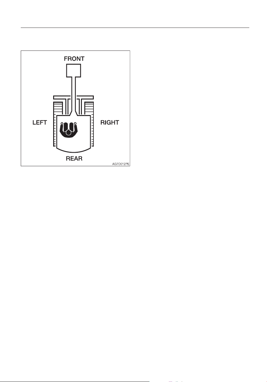
MACHINE DESCRIPTION
FRONT, REAR, LEFT AND RIGHT
This manual refers the front, rear, left and
right of the machine as seen when sitting in
the operator’s seat with the dozer blade
visible to the front.
DESIGNATED OPERATIONS
FEATURES
• “Flexible machine width mechanism” for
crawler width
• Low engine noise and exhaust emissions
BREAK-IN PERIOD
When the machine is new, operate the
machine for the first 100 hours (as indicated
on the hour meter) by following the
instructions below.
Using a new machine without a break-in
period will lead to quicker deterioration of
machine performance and may shorten the
machine’s service life.
• Sufficiently warm up the engine and
hydraulic oil.
• Avoid heavy loads and rapid operations.
Operate with a load of about 80% the
maximum load.
• Do not abruptly start up, accelerate,
change directions, or stop unless
necessary.
Use this machine primarily for the following
operations:
• Excavation
• Digging ditches
• Digging side ditches
• Leveling
• Loading
0-3
Page 6

NOTES ON READING THIS MANUAL
Please note that the descriptions and
diagrams included in this manual may not be
applicable to your machine.
The numbers used in the illustration are with
circles around them. The same numbers
appear between the parentheses in the text.
(Example:
Symbols used in this manual
The symbols used in this manual have the
following meanings.
...... Prohibition
............. Lock
............. Unlock
(1))
0-4
Page 7

Contents
Introduction .....................................0-2
Machine description ........................0-3
Safety ..............................................1-1
General precautions ................................1-2
Precautions when preparing ....................1-8
Precautions when starting .....................1-12
Precautions when operating ..................1-14
Precautions when stopping ...................1-23
Precautions when transporting ..............1-24
Precautions on maintenance .................1-26
Safety signs (decals) .............................. 1-35
Controls ...........................................2-1
Names of components (Cab) ................... 2-2
Names of components (Canopy) ............. 2-4
Covers ..................................................... 2-6
Starter key ........................................... 2-6
Maintenance cover .............................. 2-6
Fuse box ............................................. 2-7
Tool case ............................................. 2-7
Grease gun holder ............................... 2-7
Fuel lid ................................................. 2-8
Fuel filler port ....................................... 2-8
Side cover ........................................... 2-9
Engine hood ........................................ 2-9
Cab ....................................................... 2-10
Cab door ........................................... 2-10
Emergency exit .................................. 2-10
Front window .....................................2-11
Lower front window ........................... 2-12
Side window ...................................... 2-12
Emergency hammer (optional) ........... 2-13
Seat and seat belt ................................. 2-14
Seat (If equipped) .............................. 2-14
High-back seat (If equipped) .............. 2-15
Seat belt ............................................ 2-16
Instrument cluster .................................. 2-18
Warning lamps ...................................2-18
Indicators........................................... 2-19
Meters ............................................... 2-19
Multi-data display .............................. 2-20
Switches ............................................... 2-26
Starter switch .................................... 2-26
Horn button ....................................... 2-26
Travel speed switch ........................... 2-26
Wiper switch ...................................... 2-27
Second auxiliary hydraulic switch ....... 2-27
Third auxiliary hydraulic switch and
button
................................................ 2-27
Overload warning switch
(If equipped)
Levers and Pedals ................................. 2-29
Safety lock lever ................................ 2-29
Throttle lever ...................................... 2-29
Operating levers ................................ 2-30
Blade lever ......................................... 2-30
Travel levers/pedals ........................... 2-31
Boom swing pedal ............................. 2-31
Auxiliary hydraulic pedal ..................... 2-32
Selector lever .................................... 2-32
Accessories ........................................... 2-34
Heater ............................................... 2-34
Cup holder ........................................ 2-36
Interior light ........................................ 2-36
Inside rear view mirror (cab) ...............2-36
Power sockets .................................. 2-37
Armrest..............................................2-37
Radio (for cab) ................................... 2-38
Auxiliary hydraulic lines ...................... 2-42
Accumulator (If equipped) .................. 2-46
....................................... 2-28
Operation .........................................3-1
Before starting operation .........................3-2
Getting on or off the machine ...............3-2
Walk-around inspection .......................3-2
Daily inspection .................................... 3-2
Starting and stopping the engine ............. 3-3
Before starting the engine .................... 3-3
Starting the Engine .............................. 3-4
Warming up the engine ........................ 3-5
Stopping the engine ............................ 3-5
Operating the machine ............................ 3-6
Lever pattern (ISO pattern) ................... 3-6
Lever pattern (G pattern) If equipped ... 3-7
Warming up the machine (hydraulic oil) 3-8
Inspection after warm-up ..................... 3-9
Crawler width switching ..................... 3-10
Switching the blade width .................. 3-11
Operating the travel levers ................. 3-12
Stopping travel .................................. 3-15
Operating the working equipment ...... 3-16
Operating procedures ............................ 3-18
Prohibited operations .........................3-18
Cautions on operating ........................... 3-21
Cautions on traveling ......................... 3-21
Cautions on traveling on slopes ........ 3-22
Getting out of mud ............................ 3-24
0-5
Page 8

Operations possible with this
machine............................................. 3-24
Parking the machine
Parking .............................................. 3-26
Inspection and checks after stopping
the engine.......................................... 3-26
Handling in cold climates
Preparing for cold climates ................3-27
Cautions after operations ................... 3-27
After the cold climate ......................... 3-27
Handling rubber crawlers ....................... 3-28
Prohibitions ........................................3-28
Cautions ............................................ 3-29
Preventing the rubber crawlers from
coming off .........................................3-29
.............................. 3-26
....................... 3-27
Transport .........................................4-1
Loading and unloading ............................ 4-2
Hoisting the machine ............................... 4-4
Securing the machine .............................. 4-6
Maintenance ....................................5-1
General .................................................... 5-2
Maintenance overview ......................... 5-2
Cautions on maintenance .................... 5-2
Service data ............................................ 5-4
Fuel and lubricant table ........................ 5-4
Regularly replace the hydraulic oil ........ 5-8
List of consumables ............................. 5-9
List of tools ........................................ 5-10
List of tightening torques ...................5-11
Safety-critical parts ................................ 5-12
Maintenance list ..................................... 5-14
Walk-around inspection .........................5-16
Inspecting by opening the engine hood
and covers......................................... 5-16
Inspecting by walking around the
machine............................................. 5-17
Inspecting while sitting in the
operator’s seat
Daily inspection (every 10 hours) ............ 5-18
Inspecting and replenishing the
coolant
Inspecting and replenishing the
engine oil
Inspecting the dust indicator .............. 5-19
Inspecting the water separator ........... 5-20
Inspecting the fuel level ...................... 5-20
Inspecting the hydraulic oil tank level
and replenishing
................................... 5-17
.............................................. 5-18
........................................... 5-19
................................ 5-21
Lubricating the working equipment .... 5-23
After the initial 50 hours
(only for new machines)
Replacing the engine oil and the
............................................... 5-24
oil filter
Inspecting and adjusting the fan belt .. 5-25
Replacing the hydraulic oil return filter 5-26
Every 50 hours ...................................... 5-28
Inspecting and adjusting the crawler
tension .............................................. 5-28
Lubricating the slew bearing .............. 5-30
Lubricating the slew motor pinion ...... 5-30
Draining the water from the fuel tank ..5-31
Inspecting the battery fluid level and
replenishing .......................................5-32
Every 100 hours .................................... 5-34
Cleaning the water separator ............. 5-34
Cleaning the fuel filter ......................... 5-34
After the initial 250 hours
(only for new machines)
Replacing the travel motor gear oil ..... 5-35
Every 250 hours .................................... 5-36
Replacing the engine oil and the oil
filter
................................................... 5-36
Inspecting and adjusting the fan belt .. 5-36
Cleaning the air cleaner ..................... 5-36
Cleaning the radiator fins and oil
cooler fins
Cleaning the air filters ......................... 5-39
Every 500 hours .................................... 5-40
Replacing the hydraulic oil return filter 5-40
Replacing the water separator filter .... 5-40
Replacing the fuel filter ....................... 5-41
Every 1000 hours .................................. 5-42
Replacing the travel motor gear oil ..... 5-42
Cleaning the engine cooling system ... 5-42
Replacing the air cleaner element ...... 5-44
Inspecting and adjusting the engine
valve clearance
Retightening the engine cylinder
head bolt
Every 1500 hours .................................. 5-46
Inspecting and cleaning the engine
fuel injectors
Inspecting the crankcase breather
system
Every 2000 hours .................................. 5-47
Lapping the engine valve seats .......... 5-47
Every 4000 hours .................................. 5-48
0-6
.......................................... 5-38
........................................... 5-45
...................................... 5-46
............................................... 5-46
......................... 5-24
......................... 5-35
.................................. 5-45
Page 9

Replacing the hydraulic oil and
cleaning the suction strainer
When required ....................................... 5-50
Replacing the bucket teeth ............... 5-50
Replacing the bucket ......................... 5-52
Lubricating the levers ......................... 5-54
Inspecting the rubber crawlers ........... 5-55
Replacing the rubber crawlers ........... 5-56
Maintenance during extended storage
period
.................................................... 5-58
.............. 5-48
Troubleshooting ...............................6-1
Symptoms that are not malfunctions .......6-2
If the engine overheats ............................. 6-3
If the battery goes dead ........................... 6-4
If a fuse blows ......................................... 6-6
Inspecting and replacing the fuse .........6-6
Inspecting the fusible link ..................... 6-7
Restarting after adding fuel ...................... 6-8
Bleeding air from the fuel system ......... 6-8
If a warning lamp flashes ......................... 6-9
Other symptoms .................................... 6-10
Lowering the boom to the ground .........6-12
Towing ...................................................6-13
If the cab or canopy is damaged ........... 6-14
Specifications ..................................7-1
Basic Specifications ................................. 7-2
Machine dimensions ................................ 7-4
Operating ranges ..................................... 7-8
Lifting Capacities ................................... 7-11
Options ............................................8-1
General precautions ................................8-2
Safety precautions ............................... 8-2
Cautions when installing attachments .. 8-2
Cautions when operating attachments . 8-3
Attachment combination table ................. 8-4
Selecting a lever pattern .......................... 8-5
Switching the lever pattern .................. 8-5
Hydraulic breaker ....................................8-6
Replacing the hydraulic oil regularly .....8-7
Load safety device ................................... 8-8
Emergency shut-off valve .....................8-8
Overload warning device ..................... 8-9
Travel alarm ........................................... 8-10
Optional equipment mass ..................... 8-11
Biodegradable oil ................................... 8-12
Replacing the hydraulic oil with
biodegradable oil ............................... 8-12
0-7
Page 10

0-8
Page 11

SAFETY
1-1
Page 12

Safety
GENERAL PRECAUTIONS
GENERAL PRECAUTIONS
It is your responsibility to observe all
pertinent laws and regulations and to
follow the manufacture’s instructions on
machine operation, inspection and
maintenance.
Virtually all accidents occur as the result of a
failure to observe basic safety rules and
precautions.
Most accidents can be prevented by
identifying the potentially hazardous
situations beforehand.
Read and understand all safety messages
which describe how to prevent accidents.
Do not operate the machine until you are
sure that you have gained a proper
understanding of its operation, inspection
and maintenance.
Observe all safety rules
• Operation, inspection and maintenance of
this machine must be performed only by a
trained and qualified person.
• All rules, regulations, precautions and
safety procedures must be understood and
followed when performing operation,
inspection and maintenance of this
machine.
• Do not perform any operation, inspection
and maintenance of this machine when
under the adverse influence of alcohol,
drugs, medication, fatigue, or insufficient
sleep.
When a problem is found on the machine
If any problem (noise, vibration, smell,
disorder of instrument, smoke, oil leak,
wrong indication of alarm or unusual
indication in the instrument cluster, etc.) is
detected during the operation or inspection
and maintenance of the machine,
immediately inform your sales or service
dealer and take proper actions. Do not
operate the machine until the trouble is
cleared.
Operating temperature range
To maintain the performance of machine and
to prevent it from early wear, observe the
following operating conditions.
• Do not operate the machine if the ambient
temperature is higher than +45°C (+113°F)
or lower than –15°C (+5°F).
· If operated at an ambient temperature of
higher than +45°C (+113°F), the engine
may overheat and cause the engine oil to
degrade. Also, the hydraulic oil may
become very hot, causing damage to the
hydraulic equipment.
· If operated at an ambient temperature of
lower than –15°C (+5°F), the parts made
of rubber such as gaskets may get
hardened to cause an early wear or
damage to the machine.
· If the machine is to be used outside the
ambient temperature range described
above, consult your sales or a service
dealer.
1-2
Page 13
Safety
GENERAL PRECAUTIONS
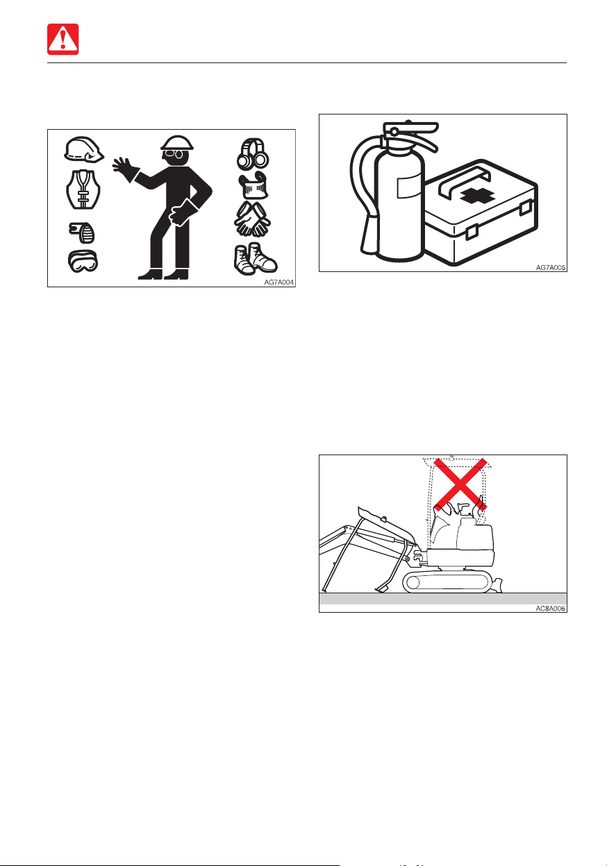
Wear appropriate clothing and protective
equipment
• Do not wear loose clothing or any
accessory that can catch on controls or in
moving parts.
• Do not wear oily or fuel stained clothing
that can easily catch fire.
• Wear a hard hat, safety shoes, safety
glasses, filter mask, heavy gloves, ear
protection and other protective equipment
as required by job conditions. Wear
required appropriate equipment such as
safety glasses and filter mask when using
grinders, hammers or compressed air, as
metal fragments or other objects can fly
and cause serious injury.
• Use hearing protection when operating the
machine. Loud prolonged noise can cause
hearing impairments, even the total loss of
hearing.
Install a fire extinguisher and first aid kit
Be prepared for fire and accidents
• Install an extinguisher and a first aid kit,
and learn how to use them.
• Lean how to fight a fire and how to deal
with accidents.
• Know how to contact emergency
assistance and make a list of emergency
contacts.
Never remove safety equipment
• Make sure all protective guards, canopies
and doors are in place and secured. Repair
or replace damaged parts before operating
the machine.
• Know how to use the safety lock lever, seat
belt and other safety equipment and use
them properly.
• Never remove any safety equipment except
for servicing. Keep all safety equipment in
good operating condition.
1-3
Page 14
Safety
GENERAL PRECAUTIONS
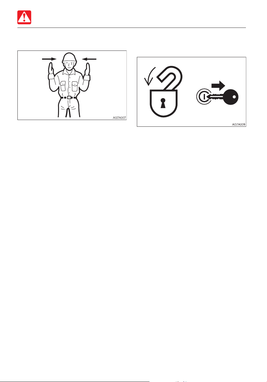
Use a signal person and a flag person
Learn how to use the hand signals required
for particular jobs and make sure who has
the responsibility for signaling.
• All personnel must fully understand all the
signals.
• The operator must respond to signals only
from the appointed signal person, but must
obey a stop signal at any time from
anyone.
• The signal person must stand in a clearly
visible location when giving signals.
Cautions when standing up from or
leaving the operator’s seat
• Before standing up from the operator’s
seat to open/close the window or remove/
install the lower window, lower the working
equipment to the ground, raise the safety
lock levers to engage the lock and stop the
engine. If any controls should be
accidentally touched when the safety lock
levers is lowered (unlocked), the machine
will suddenly move and cause serious
injury or death.
• Note that the dozer blade, boom swing
and auxiliary hydraulic controls cannot be
locked, even when the safety lock lever is
set to the locked position.
Do not carelessly touch these controls.
• Be careful not to touch the operating levers
when raising or lowering the safety lock
levers.
• Before leaving the operator’s seat, lower
the working equipment to the ground, raise
the safety lock levers to engage the lock
and stop the engine. Also, be sure to
remove the key, lock the door and covers,
take it with you and store it in a specified
place.
1-4
Page 15

Safety
GENERAL PRECAUTIONS
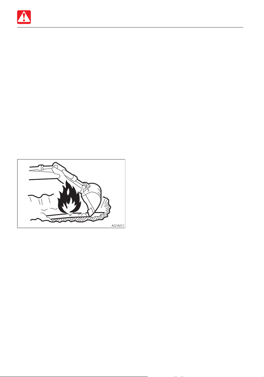
Avoid fire and explosion hazards
Keep flames away from fuel, oil, grease and
antifreeze. Fuel is particularly flammable and
dangerous.
• When handling these combustible
materials, keep lit cigarettes, matches,
lighters and other flames or sources of
flames away.
• Do not smoke or permit open flames while
handling fuel or working on the fuel system.
• Do not leave the location while refilling with
fuel or oil.
• Never remove the fuel cap or add fuel
when the engine is running or still hot. Also,
do not spill the fuel on the hot surface of
the machine or the component of the
electric system.
• Clean up spilled fuel or oil immediately.
• Check for fuel, oil leak. Stop all leaks and
clean the machine before operating.
• When operating with grinder or welding,
move inflammables to a safe place.
• Do not cut or weld on pipes or tubes that
contain flammable fluids. Clean thoroughly
with nonflammable solvent before cutting
or welding.
• Remove all trash or debris from the
machine. Make sure that oily rags or other
flammable material are not stored on the
machine.
• Handle all solvents and dry chemicals
(foam type fire extinguisher) according to
procedures identified on manufacturer’s
containers. Work in a well-ventilated area.
• Never use fuel for cleaning purposes.
Always use a nonflammable solvent.
• When handling the fuel, washing oil or
paint, open the door and windows to
ventilate thoroughly.
• Store all flammable fluids and materials in a
safe and well-ventilated place.
• The short circuit of the electric system may
cause the fire. Check for any loosened
connections or damage to the wires every
day. Retighten the loosened connector and
wire clamp. Fix or change the damaged
wire.
• Fire from the pipes:
Make sure that the clamps, guards and
cushions of the hoses and tubes are
securely fixed. If not, hoses or tubes may
be damaged due to vibration or contact
with other parts during operation. This can
cause the high-pressure oil to spurt out,
resulting in the fire or injury.
1-5
Page 16
Safety
GENERAL PRECAUTIONS
Exhaust fumes from the engine is
poisonous
• Do not operate the engine in an enclosed
area without adequate ventilation.
• If natural ventilation is not possible, install
ventilators, fans, exhaust extension pipes
or other venting devices.
Handling asbestos dust
Inhaling asbestos dust can cause lung
cancer. When handling the materials which
may contain asbestos, take the following
precautions:
• Never use compressed air for cleaning.
• Avoid brushing or grinding parts containing
asbestos.
• For clean up, use a vacuum equipped with
a high efficiency particulate air filter (HEPA).
• Wear the stipulated respirator if there is no
other way to control the dust. When
working indoors, install a ventilation system
with a macromolecular filter.
• Do not allow unauthorized personnel in the
work area while working.
• Follow the rules and environmental
standard applicable to the work area.
Be careful not to get crushed or cut
Never put your hands, feet or other parts of
your body between the upperstructure and
the undercarriage or tracks, between the
machine body and working equipment, or
between a cylinder and moving part. The
sizes of these gaps change when the
machine moves, and a person can suffer
severe injury or death.
1-6
Page 17

Safety
GENERAL PRECAUTIONS
Using optional products
• Consult with Takeuchi before installing
optional attachments. Depending on the
type of attachments or the combination of
them, the attachment may come into
contact with the operator’s compartment
or the other parts of the machine. Make
sure that the optional attachment installed
is not contacted with other parts before
use.
• Do not use attachments that have not
been approved by Takeuchi. Doing so may
compromise safety or adversely affect the
machine’s operation or service life.
• Takeuchi will not be held responsible for
any injuries, accidents or damage to its
products caused by the use by a nonapproved attachment.
Never modify the machine
Unauthorized modifications to this machine
can cause injury or death. Never make
unauthorized modifications to any part of this
machine.
1-7
Page 18
Safety
PRECAUTIONS WHEN PREPARING
PRECAUTIONS WHEN
PREPARING
Know the work area
Before starting operation, know the working
area condition to ensure a safety operation.
• Inspect the topography and ground
condition of the working area, or the
structure of the building when working
indoors, and take the safety precautions as
necessary.
• Be sure to avoid all hazards and
obstructions such as ditches, underground
lines, trees, cliffs, overhead electrical wires,
or places where there is a danger of falling
rocks or slides.
• Check with the administrator for the
locations of buried gas pipes, water pipes
and power cables. If necessary, determine
what specific precautions must be taken to
insure safety by consulting with the
administrator.
• When working on roads, be sure to
consider the safety of pedestrians and
vehicles.
· Use a flag person and/or a signal.
· Fence off the working area and keep off
unauthorized persons.
• When working in water or crossing shallow
streams or creeks, check the depth of the
water, the solidity of the ground and the
water flow speed beforehand.
Refer to “Cautions on operating” for further
instructions.
1-8
Page 19
Safety
PRECAUTIONS WHEN PREPARING
Check the strength of the bridge
When traveling over a bridge or a structure,
check the permissible load. If the strength is
insufficient, reinforce the bridge or the
structure.
Always keep the machine clean
• Clean windows, mirrors and lights to
ensure good visibility.
Adjust the mirror to the best position for
the operator to see the rear view (blind
spot) from the operator’s seat.
• Wipe off any oil, grease, mud, snow or ice,
to prevent accidents due to slipping.
• Remove all loose objects and unnecessary
devices from the machine.
• Remove any dirt, oil or grease from the
engine area to prevent fires.
• Clean around the operator’s seat and
remove any unnecessary object from the
machine.
1-9
Page 20

Safety
PRECAUTIONS WHEN PREPARING
Perform inspection and maintenance
every day
Failure to identify or repair the irregularities or
damage on machine can lead to accidents.
• Before operating, perform the specified
inspection and make prompt repairs where
necessary.
• If a failure occurs and the operation
becomes impossible or the engine fails,
immediately stop the machine by following
the shutdown procedure, and keep
machine securely parked until the
malfunction is corrected.
Cautions in the operator’s compartment
• Remove mud and grease from shoe soles
before entering the operator’s
compartment. Pedaling the machine with
the shoes with mud and grease will cause
a slip accident.
• Do not leave the parts or tools around the
operator’s seat.
• Do not leave any plastic bottles in the
operator’s compartment or attach any
suction cups on the window glass. The
plastic bottle or suction cup act as a lens
and can cause fire.
• Do not use the mobile phone during
traveling or working.
• Do not bring combustibles or explosives
into the operator’s compartment.
• Do not leave the cigarette lighter in the
operator’s compartment. When the room
temperature rises, the lighter may explore.
1-10
Page 21
Safety
PRECAUTIONS WHEN PREPARING
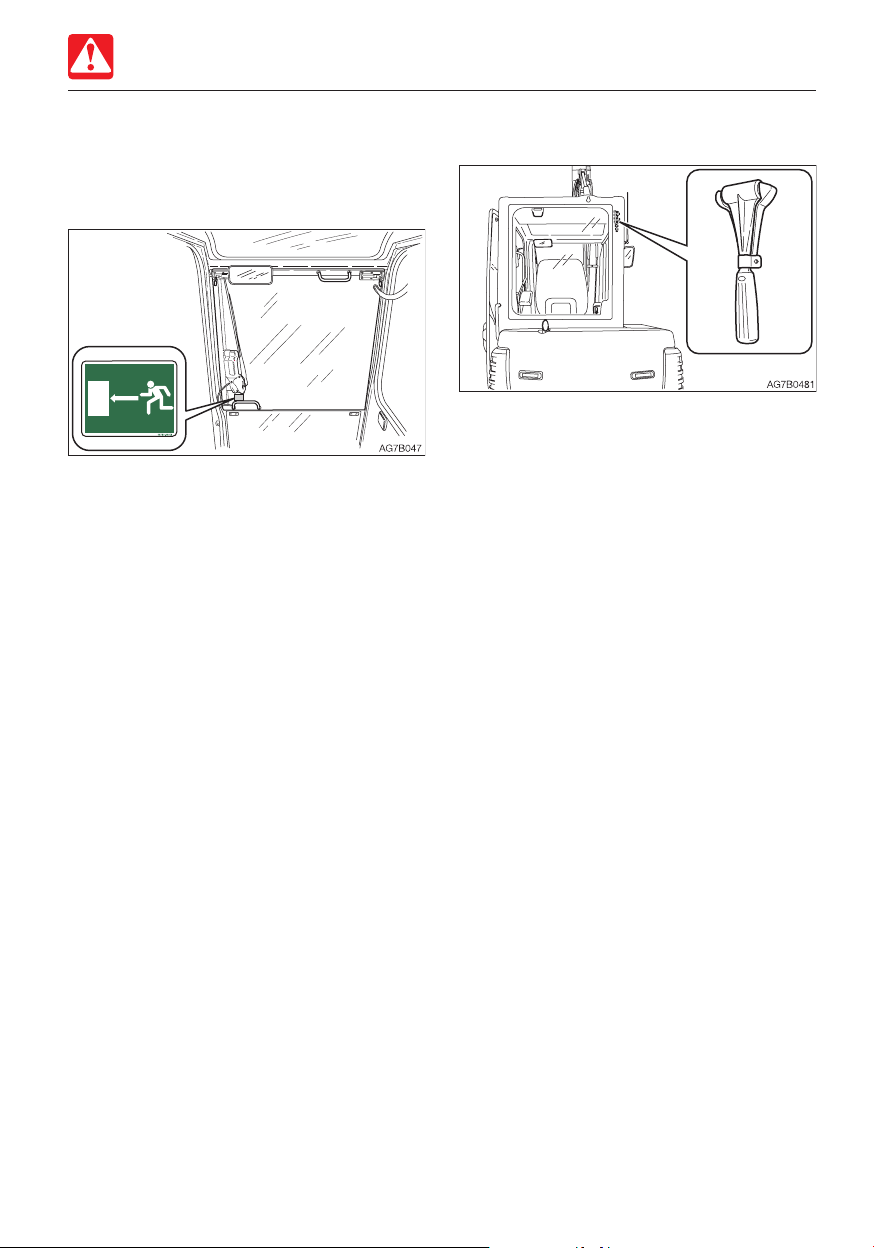
Emergency exit
Front window (excluding machines with a
front guard)
If you should become trapped inside the
cab, open the front window to get out.
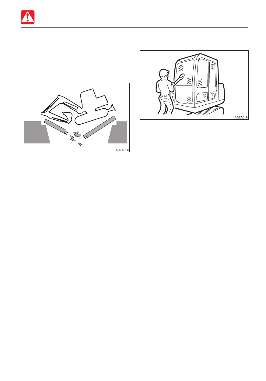
Emergency hammer (optional)
An emergency hammer is installed to be
used to escape from the cab in an
emergency. When escaping, break the
windows with the hammer.
• When breaking the windowpane with a
hammer, take great care not to injure
yourself with the broken glass pieces.
• Remove the glass pieces from the window
sill so as not to cut yourself when
evacuating. Broken glass will fall from the
window, so be careful of your footing and
do not slip on the glass.
1-11
Page 22
Safety
PRECAUTIONS WHEN STARTING
PRECAUTIONS WHEN
STARTING
Support your weight in a three point
secure stance when getting on/off the
machine
• Do not jump on or down from the machine.
Never attempt to get on or off the moving
machine.
• When getting on or off the cab, first fully
open the door to the locked position and
check that it does not move (for machines
with cab).
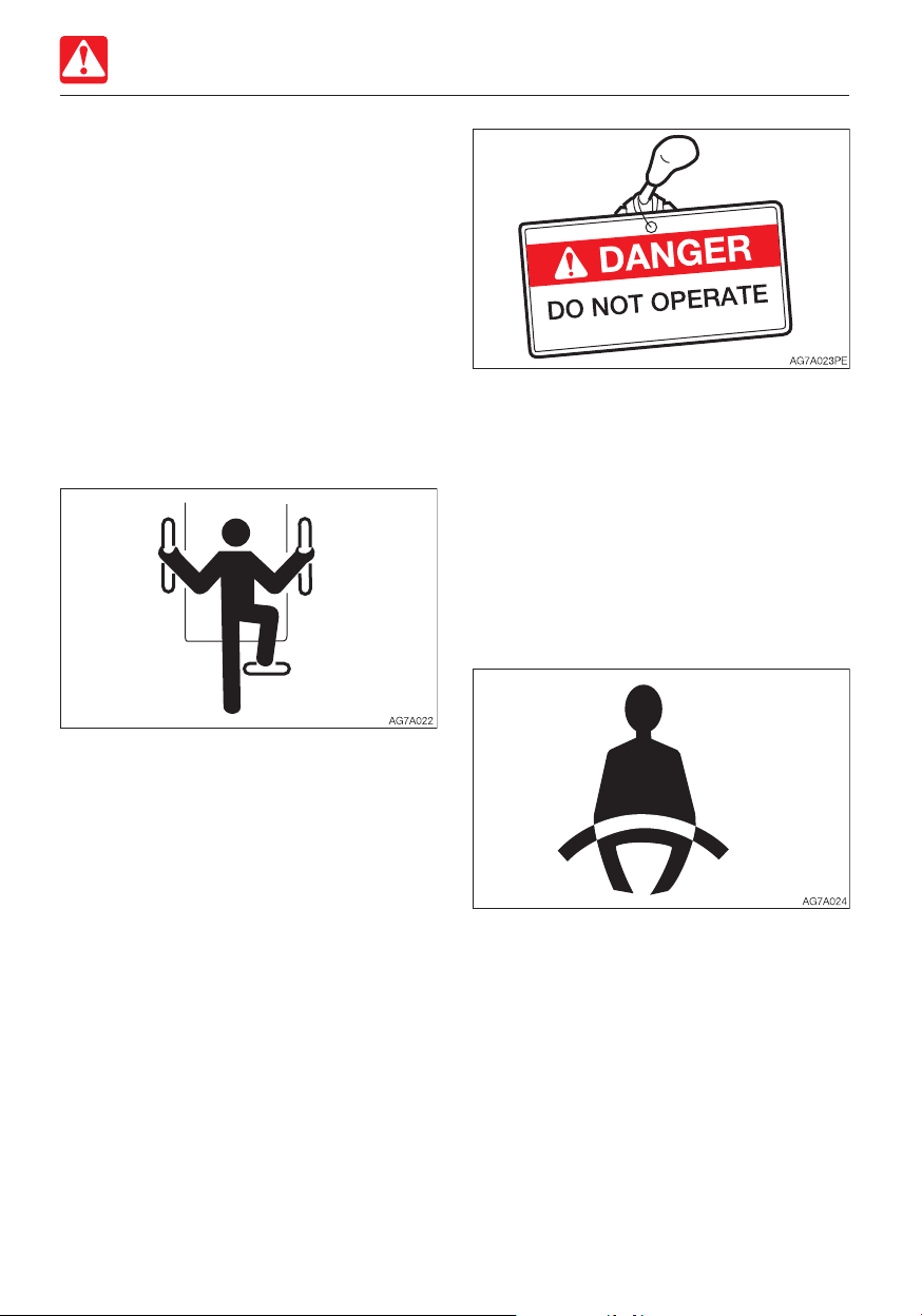
• Check if there is a “DO NOT OPERATE”
alert sign or similar sign is on the cab door,
controls or starter switch. If there is one, do
not start the engine or touch any levers.
• Sound the horn to warn people around the
machine.
Sit in the operator’s seat and start the
engine
• Adjust the seat to securely latch it.
• Climb up/down the steps facing the
machine and holding the handrail to
support your weight in a three point secure
stance (hand and feet).
• Never use the safety lock lever or control
levers as hand holds.
Before starting the machine, ask any
unauthorized personnel to leave the area
Do not start the engine until you are sure it is
safe to start the machine by checking the
following items.
• Walk around the machine and warn the
person who is servicing the machine or is
walking near the machine. Do not start the
machine until you are certain that no one is
around the machine.
• Fasten the seat belt.
• Check if the parking brake is on and all
control levers and pedals are in the neutral
position.
• Check if the safety lock lever is in the lock
position.
• Make sure that no one is near the machine.
• Start and operate the machine only from
the operator’s seat.
• Never attempt to start the engine by
shorting across the starter terminals.
1-12
Page 23

Safety
PRECAUTIONS WHEN STARTING
Starting with jumper cables
Use jumper cables only in the recommended
manner. Improper use of jumper cables can
result in battery explosion or unexpected
machine motion.
Refer to “If the battery goes dead” for further
instructions.
After starting the engine
After starting the engine, perform the
operations and checks described below in a
safe place with no persons or obstacles in
the area. If any malfunction is found, follow
the shutdown procedure and report the
malfunction.
• Warm up the engine and hydraulic oil.
• Check if all gauges and warning devices
are properly working.
• Check for any noises.
• Test the engine speed control.
• Operate each control to ensure they are
properly working.
In cold climates
• Be careful of slippery conditions on freezing
ground, steps and hand holds.
• In severe cold climates, do not touch any
metal parts of the machine with bare
hands. The skin will freeze to the metal,
resulting in severe injury.
• Do not use ether or starting fluid on this
engine. The starting fluids can cause
explosion and serious injury or death.
• Warm up the engine and hydraulic oil. If the
levers are operated without warming, the
machine will not react or move promptly or
properly, resulting in accident.
1-13
Page 24
Safety
AD6A001
PRECAUTIONS WHEN OPERATING
PRECAUTIONS WHEN
OPERATING
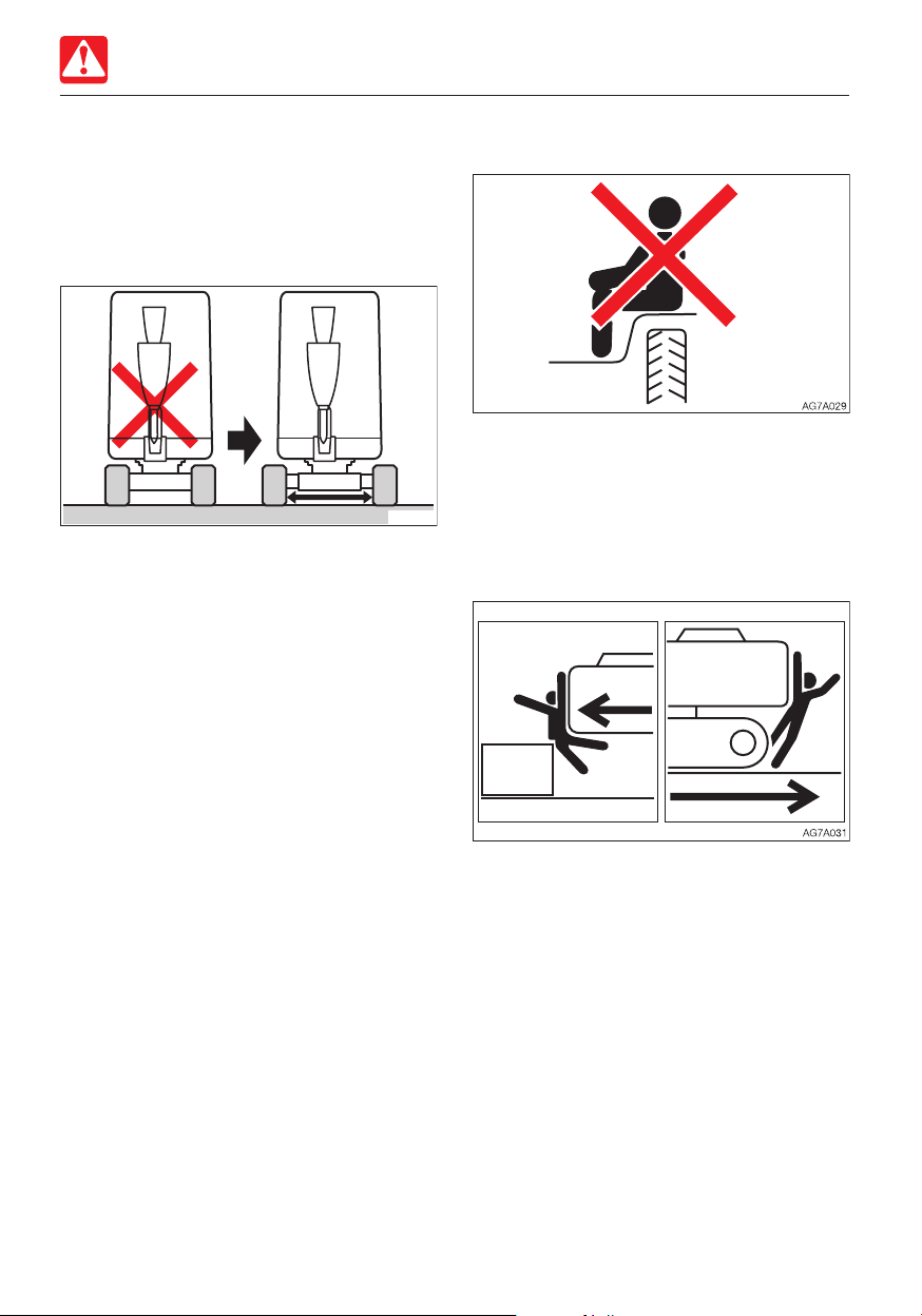
Operate the machine with the maximum
crawler width
• Always operate the machine with the
crawler width extended to 1300 mm (51.2
in.) to maximize the machine stability. If the
machine is operated with the crawler width
narrowed (980 mm, 38.6 in.), the machine
may tip over due to its poor stability.
• If the machine must be operated with the
narrowed crawler width (980 mm, 38.6 in.),
traveling should be done after folding the
hoe attachment, lowering the boom to
lower the center of gravity and keeping the
machine facing forward.
Do not permit riders on the machine
Do not allow anyone to ride on any part of
the machine at any time while traveling or
operating.
Check if the work area is safe and secure
before operation
Ensure good visibility
• When working in dark places, turn on the
machine’s working lights and headlights
and additional lighting equipment installed,
as necessary.
• When visibility is poor due to bad weather
(fog, snow, rain or a cloud of dust), stop
operating the machine and wait until
visibility improves.
• Confirm the performance limits of the
machine.
• Use a signal person at road shoulders,
narrow places or where your vision is
obstructed.
• Never allow anyone to enter the machine’s
slewing radius and path.
• Signal your intention to move by sounding
the horn.
• There is a blind spot in the rear of the
machine. Before traveling in reverse, check
that the area is safe and clear.
1-14
Page 25
Safety
PRECAUTIONS WHEN OPERATING
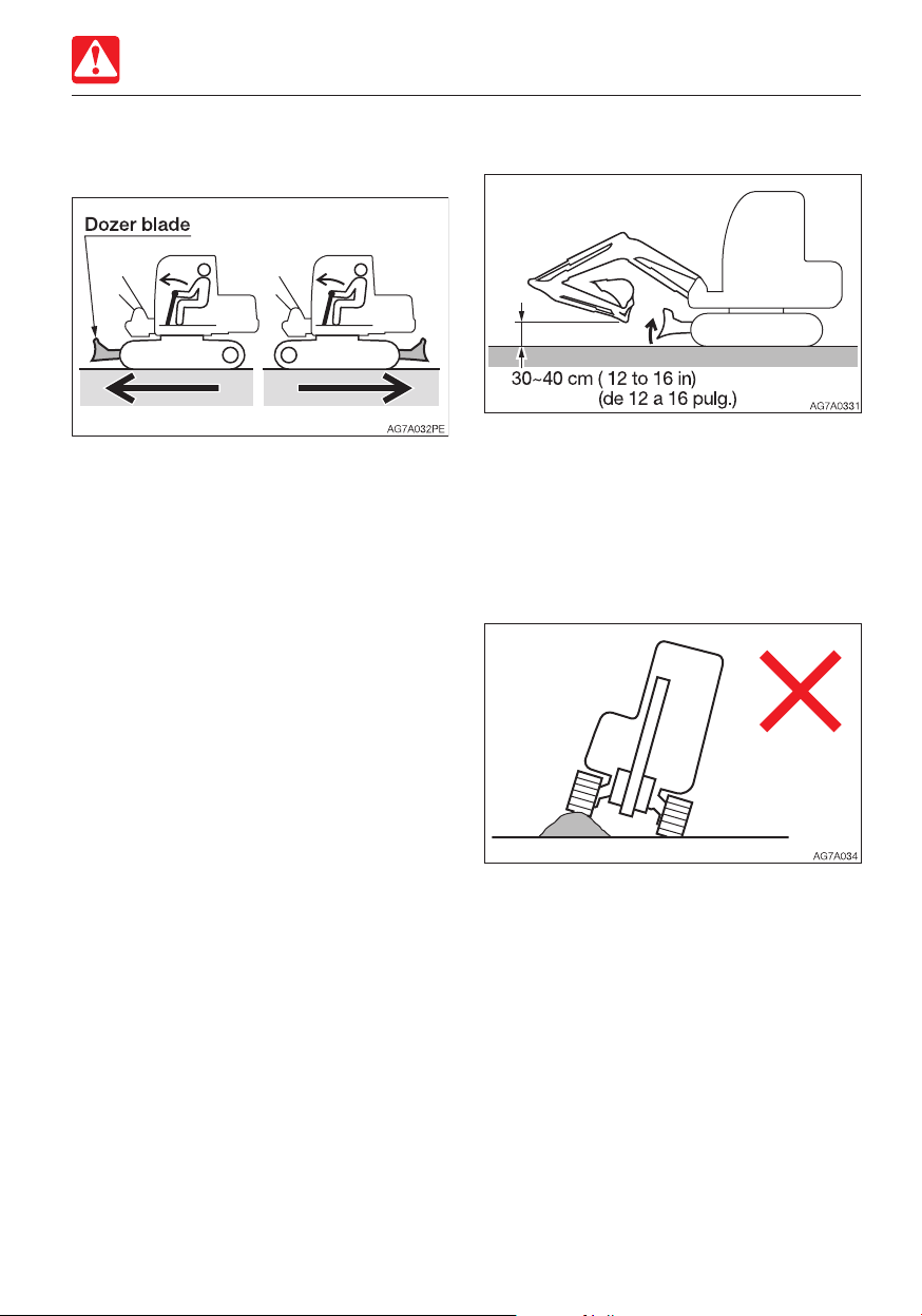
Check the position of the undercarriage
(tracks) before traveling
Before operating the travel levers/pedals,
make sure that the dozer blade is to the front
of the operator’s seat. Remember that when
the dozer blade is to the rear of the
operator’s seat, the travel levers/pedals must
be operated in the reverse direction from
when it is to the front.
Travel safely
• Travel with the dozer blade raised, the hoe
attachment folded as shown on the figure
above, and the bucket raised 30 to 40 cm
(12 to 16 in.) above the ground.
• Do not slew while traveling. If you must
operate the hoe attachment while traveling,
operate at speeds slow enough so you
have complete control at all times.
• Avoid crossing over obstacles whenever
possible. If you must do so, keep the hoe
attachment close to the ground level and
travel slowly. Never cross obstacles which
will tilt the machine to an angle of 10° or
greater.
• On uneven ground, maintain the low speed
and avoid starting, stopping or changing
directions abruptly. Otherwise, the working
equipment may come in contact with the
ground, causing the machine to lose its
balance and get damaged or to damage
the structures in the surrounding area.
1-15
Page 26
Safety
PRECAUTIONS WHEN OPERATING
Cautions on traveling on slopes
When traveling on slopes or grades, be
careful that the machine does not tip (roll)
over or slide.
• Never travel on slopes that are too steep
for the machine to maintain its stability
(maximum gradeability: 30°, lateral tipping
angle: 10°). Note that in reality, the
machine’s stability becomes lower than the
above values depending on the working
condition.
• When traveling on slopes or grades, drive
slowly in 1st (low) speed. When
descending a slope, slow down the engine
speed.
• Do not descend slopes in reverse.
• Do not change directions on slopes or
traverse slopes. First return to a flat
surface, and then take an alternative path.
• The machine may slip sideways even on a
slight slope if the ground is covered with
grass or dead leaves, or when traveling on
a wet metal plate or frozen surfaces. Make
sure the machine is never positioned
sideways on slopes.
• If the machine is stalled on the slope,
return each operating lever to the neutral
position before restarting the engine.
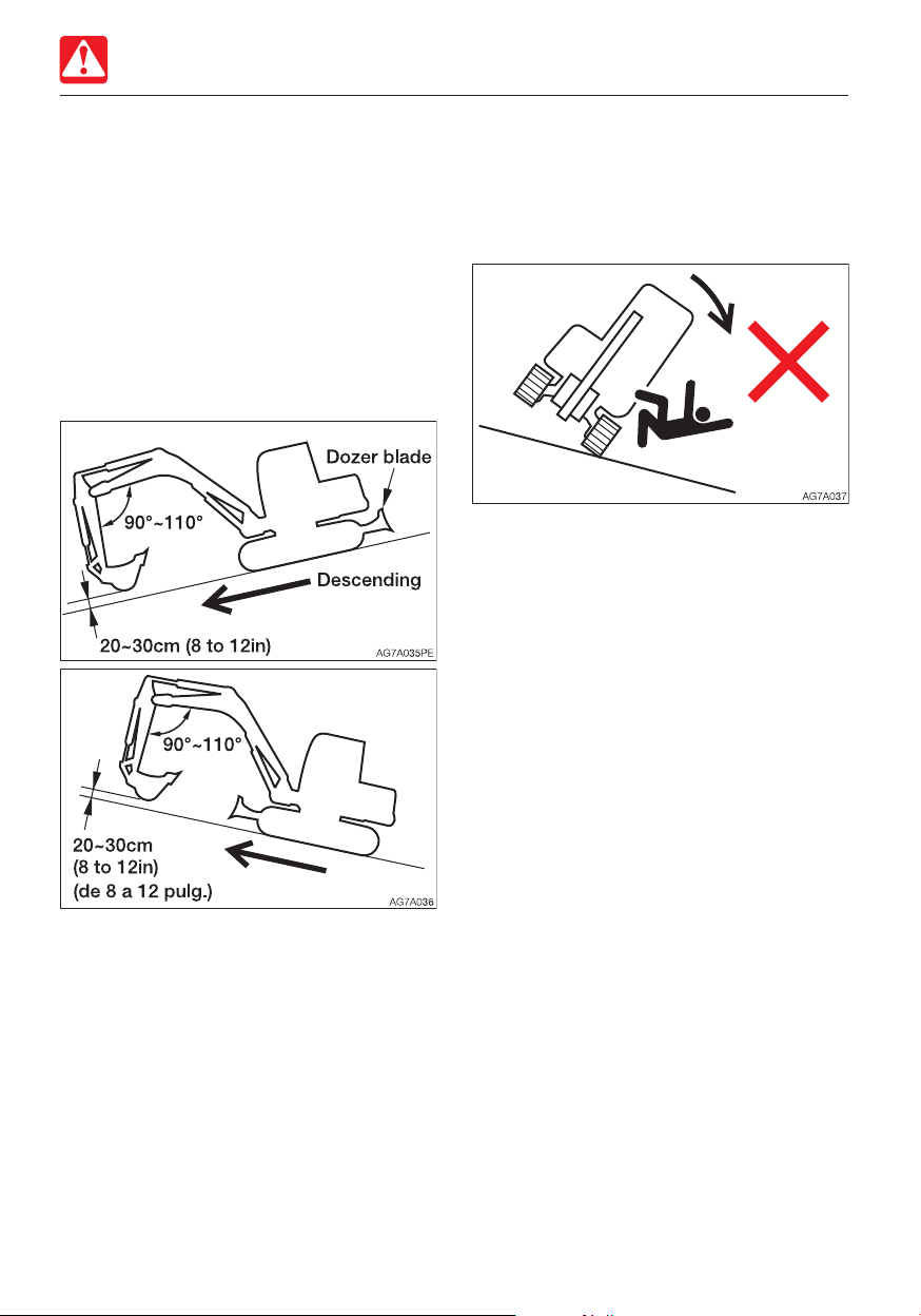
• When climbing a hill, keep the operator’s
seat facing the hillside. When descending a
hill, keep the operator’s seat facing the
downhill direction. In either case, travel
must be done while paying attention to the
ground in front of the machine.
• When traveling on slopes, lower the bucket
to a height of 20 to 30 cm (8 to 12 in.)
above the ground. When climbing a steep
slope, extend the hoe attachment to the
front. In emergencies, lower the bucket to
the ground and stop the machine.
1-16
Page 27
Safety
PRECAUTIONS WHEN OPERATING
Operate the machine on snow or ice with
extra care
• When traveling on snow or on frozen
surfaces, drive at a low speed and avoid
starting, stopping or changing directions
abruptly.
• In the snowy area, the road shoulder and
objects placed beside the road are buried
in the snow and cannot be seen. There is a
hazard of the machine tipping over or
hitting covered objects, so always carry out
operations carefully.
• If the machine enters deep snow, there is a
hazard that it may tip over or become
buried in the snow.
Be careful not to drive beyond the road
shoulder or to get trapped in a snow drift.
• With frozen ground surfaces, the ground
becomes soft when the temperature rises,
and this may cause the machine to tip
over, resulting in an operator trapped inside
the machine.
• When parking the machine on an unstable
ground, lower the dozer blade.
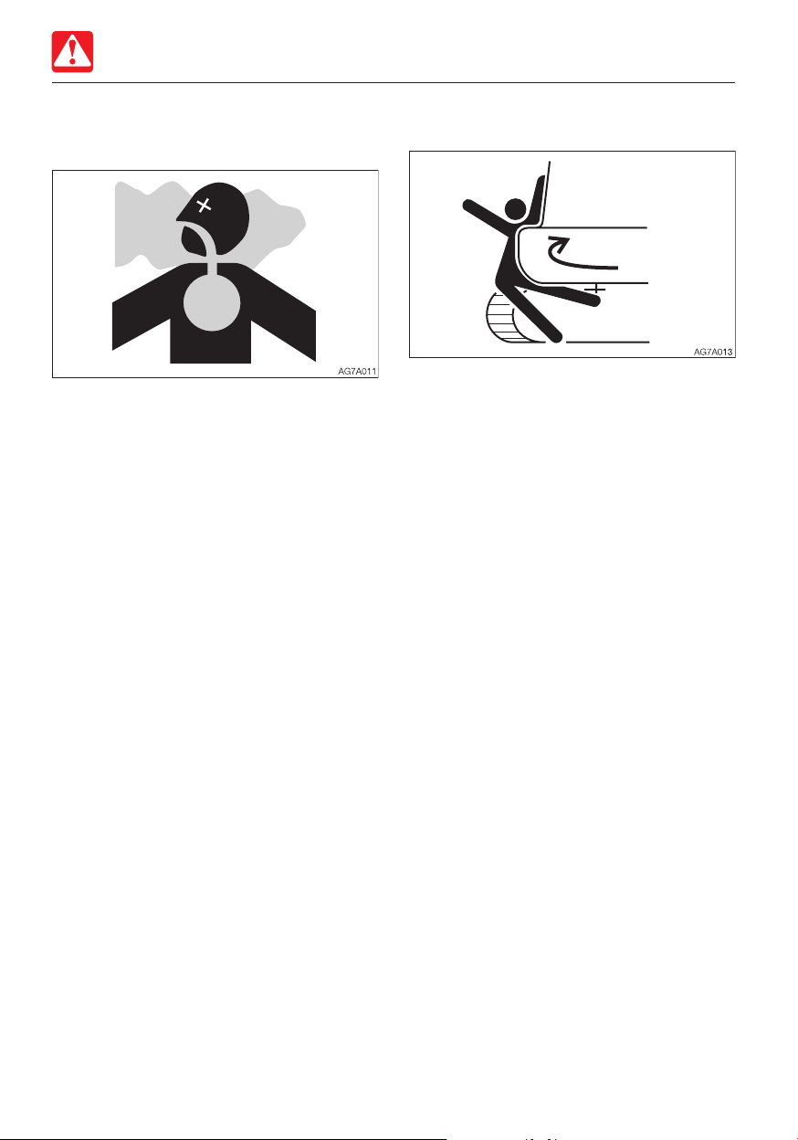
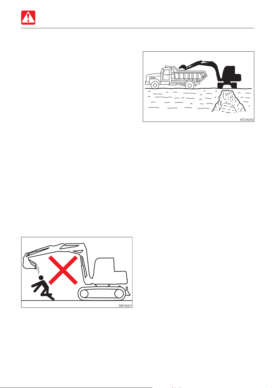
Do not move the bucket over the heads of
people
Ensure driver’s safety when loading
Do not load a truck unless the truck driver is
in a safe place.
• Never swing or position the bucket over a
person or the cab room.
• Load the truck from the rear.
Moving the bucket over the heads of people
entails the danger of the load spilling or the
sudden dropping of the bucket.
1-17
Page 28
Safety
PRECAUTIONS WHEN OPERATING
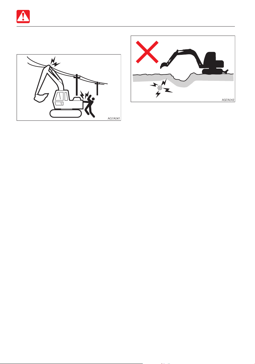
Keep a safe distance from the overhead
high-voltage cables
Never bring any part of the machine or
loaded material to near to the high voltage
cables unless all safety precautions required
by the local and national authorities have
been installed. If a person comes near to the
machine that is discharging sparks or
located near to or in contact with the power
source, there is a hazard of electric shock
and death.
• Always maintain a safe distance between
the machine and the high-voltage electric
cable.
• Check with the local power company
about safe operating procedure before
starting operations.
• Consider all cables to be high-voltage
cables and treat all cables as energized
even though it is known or believed that
the power is shut off and the cables are
visibly grounded.
• Use a signal person to give warning if the
machine approaches too close to the
high-voltage electric cables.
• Caution all personnel in the work area not
to come close to the machine or the
loaded material.
• Pay also careful attention to the highvoltage electric cables buried underground.
1-18
Page 29
Safety
PRECAUTIONS WHEN OPERATING
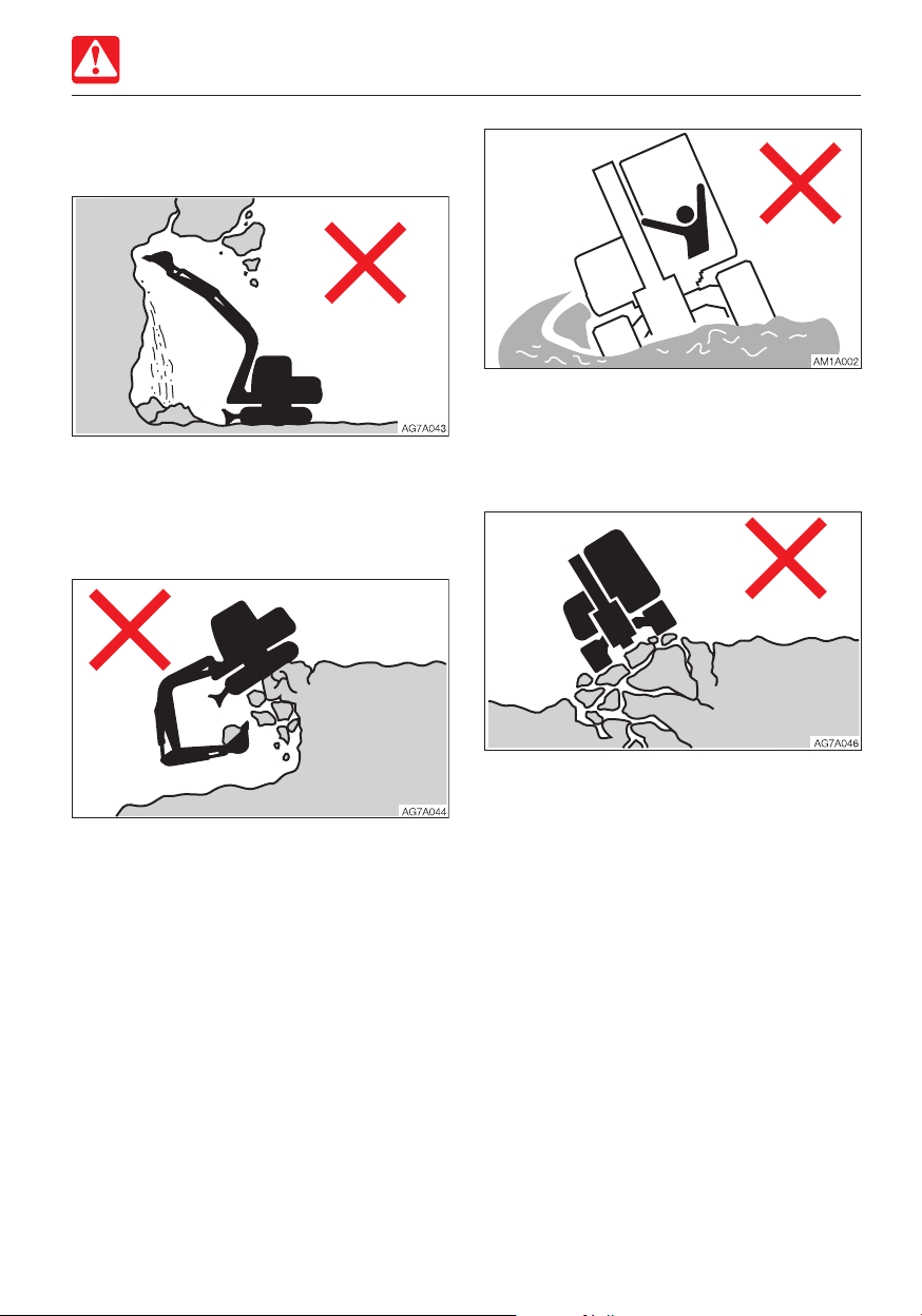
Watch out for hazardous working
conditions
• Never undercut a high bank. Doing so is
dangerous as it may cause ground
collapse.
• Do not operate in places where there is a
danger of falling rocks.
• Do not enter areas where there is soft
ground. Doing so could cause the machine
to tilt under its own weight, resulting in a
machine tipping over or sinking into the
ground.
• Maintain a safe distance between the
machine and the edge of the digging site.
Do not dig the ground under the front of
the machine.
• When working close to the cliffs or road
shoulders, to make it easier to escape if
there is any problem, set the crawlers at
right angles to the cliff or road shoulder and
the dozer blade to the front when carrying
out operations.
• Do not come close to unstable grounds
(cliffs, road shoulders, deep ditches). If the
ground should collapse under the weight
or vibration of the machine, there is a
hazard that the machine may fall or tip
over.
· Remember that the soil after heavy rain
or blasting is weak.
· The ground of top of the embankment
and of the circumferences of the
excavated ditches are also weak.
1-19
Page 30
Safety
PRECAUTIONS WHEN OPERATING
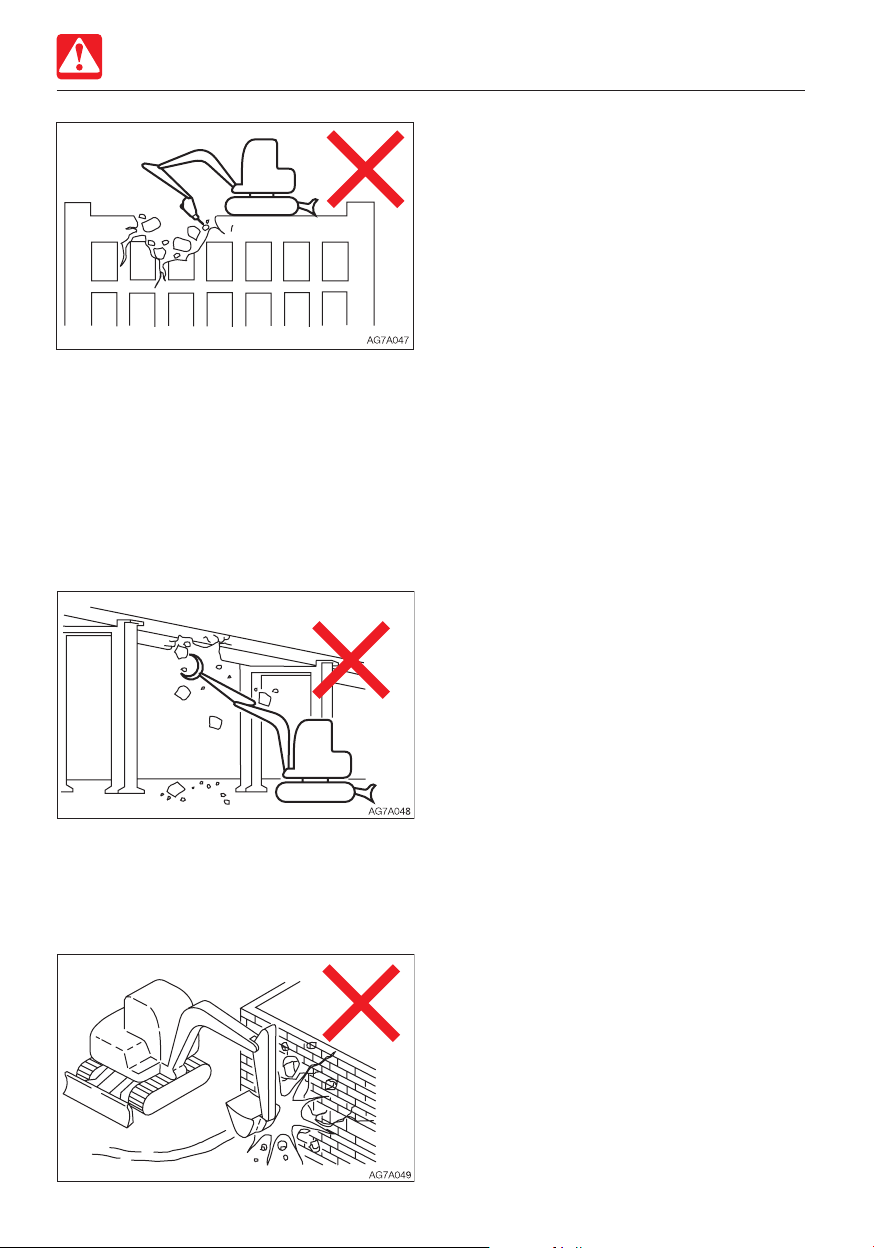
• Do not perform demolition work under the
machine. There is a hazard that the
machine may fall down, because the
ground becomes unstable.
• When working on or from the top of
buildings or other structures, check the
strength and the structure before starting
operations. If a building or structure
collapses, serious injury or damage will
result.
• Do not use the impact force of the hoe
attachment for breaking work. There is a
hazard of serious injury being caused by
flying pieces of broken materials and by the
damaged hoe attachment.
• When doing demolition work, do not
perform demolition above your head. There
is a hazard of broken parts falling or of the
building collapsing and causing serious
injury or damage.
1-20
Page 31

Safety
PRECAUTIONS WHEN OPERATING
Operating on slopes is dangerous
When operating on slopes or grades, slewing
or operation of working equipment may
cause the machine to lose stability and tip
over. Avoid operating on slopes whenever
possible.
• Level off the work area.
Never slew (swing) sideways with a heavy
load
The machine can tip over more easily in the
lateral direction than in the longitudinal
direction.
• Do not slew (swing) sideways with a heavy
load at the tip of the hoe attachment. In
particular, do not slew (swing) sideways on
slopes.
• The tip of the attachment is heavier for
machines equipped with breakers,
crushers or long arms than for machines
equipped with the standard bucket. For
such machines with heavier tips, do not
perform excavation with the digging arm
(boom) facing the downhill direction or
operate toward sideways.
• Avoid slewing to the downhill direction with
the bucket full of loaded material. This will
reduce the stability of the machine and
may result in tipping over.
Be careful with the overhead objects
When operating under bridges, in tunnels,
near electric cables or indoors, be careful not
to let the boom or arm hit overhead objects.
1-21
Page 32

Safety
PRECAUTIONS WHEN OPERATING
Excavators are not designed for lifting
loads
This machine is specifically designed for
excavation work. Therefore, it has no safety
equipment for crane operation. Extreme
caution should be paid if the excavator is
used for lifting.
• Never lift loads in excess of capacity.
Overload will cause the machine to roll and
can result in serious injury or death.
• All rated lift capacities are determined by
using a machine placed on a stable and flat
ground. For a safe lifting work, the user is
expected to make due allowance for the
particular job conditions. They include, soft
or uneven ground, non-level condition, side
loads, dynamic or jerked loads, hazardous
conditions, and experience of personnel.
The operator and other personnel should
fully acquaint themselves with the
operator’s manual before operating this
machine, and rules for safe operation of
equipment shall be adhered to at all times.
• The bucket linkage or lifting device may fail
if chains or lifting device are incorrectly
attached, resulting in serious injury or
death.
• Do not attempt to pull stumps out of the
ground when using the machine as a
crane. The loads imposed on the machine
under this use are completely unknown.
• Do not allow anyone to stand on or under
the lifted loads or come close to the work
area.
Be careful with flying objects
This machine is not equipped with protective
equipment to protect the operator from flying
objects. Do not use this machine in places
where there are risks of the operator being
hit by flying objects.
Cautions when towing
When towing, serious injury or death could
result, if performed incorrectly or the wire
rope being used is inappropriate or not
properly inspected.
• It becomes dangerous if the wire rope
breaks or becomes disengaged. Use a
wire rope appropriate for the required
tractive force.
• Do not use a wire rope that is kinked,
twisted or otherwise damaged.
• Do not apply heavy loads abruptly to the
wire rope.
• Wear safety gloves when handling the wire
rope.
• Make sure there is an operator on the
machine being towed as well as on the
machine that is towing.
• Never tow on slopes.
• Do not let anyone come near to the wire
rope while towing.
1-22
Page 33

Safety
PRECAUTIONS WHEN STOPPING
PRECAUTIONS WHEN
STOPPING
Park safely
• Park the machine on a flat, rigid and safe
ground. Set the parking brake.
• Before leaving the machine, do the
followings:
1. Lower the bucket and the dozer blade to
the ground.
2. Raise the safety lock lever to the locked
position.
3. Stop the engine and remove the starter
key.
4. Lock the cab and covers and take the
key with you.
If you must park on a slope or incline, park
the machine securely and block the
movement of the machine.
• When parking on a street, use barriers,
caution signs, lights, etc., so that the
machine can easily be seen even at night
to avoid collision with other vehicles.
1-23
Page 34

Safety
PRECAUTIONS WHEN TRANSPORTING
PRECAUTIONS WHEN
TRANSPORTING
Load/unload the machine safely
The machine may roll or tip over or fall while
being loaded or unloaded. Take the following
precautions:
• Select a firm, level surface and keep
sufficient distance from road shoulders.
• Secure the ramps of adequate strength
and size to the truck bed. The slope of the
ramps must not exceed 15°. If the rumps
are bowed down too low, support them
with poles or blocks.
• Never use the working equipment to load
or unload the machine. Doing so may
result in tipping over or falling down of the
machine.
• Keep the truck bed and loading ramps
clean of oil, soil, ice, snow, and other
materials to prevent the machine from
sliding sideways. Clean the crawlers.
• Chock the transporter wheels to prevent
movement.
• When being loaded or unloaded, travel
slowly in 1st (low) gear by following the
signal from the signal person.
• Never change courses on the ramps.
• Do not slew/swing on the ramps. The
machine may tip over.
• When slewing/swinging on the truck bed,
do it slowly as the footing should be
unstable.
• Lock the cab door after being loaded, if
applicable. Otherwise, the door may open
during transport.
• Chock the tracks and secure the machine
to the truck bed with wire rope or chain.
1-24
Page 35

Safety
PRECAUTIONS WHEN TRANSPORTING
Hoist the machine safely
• Know and use correct crane signals.
• Check the hoisting equipment for damaged
or missing parts on a daily basis and
replace as necessary.
• When hoisting, use a wire rope capable of
lifting the machine mass.
• Hoist the machine in such a manner
described in the procedure below. Do not
do it in any other manner, as it may result in
the machine losing its balance.
Refer to “Hoisting the machine” for further
instructions.
• Do not hoist the machine with an operator
on it.
• When hoisting, hoist slowly so that the
machine does not tip.
• Keep everyone out of the area when
hoisting. Do not move the machine over
the heads of the persons.
Transport the machine safely
• Know and follow the applicable safety
rules, vehicle code and traffic laws when
transporting the machine.
• Select the best transport route by
considering the length, width, height and
weight of the truck with the machine
loaded on it.
• Never abruptly start or stop or run at a high
speed at the sharp curves during transport.
Doing so will move or lose the balance of
the loaded machine.
1-25
Page 36

Safety
PRECAUTIONS ON MAINTENANCE
PRECAUTIONS ON
MAINTENANCE
Display a “DO NOT OPERATE” alert sign
Severe injury could result if an unauthorized
person should start the engine or touch
controls during inspection or maintenance.
• Before performing maintenance, stop the
engine, remove the key and take it with
you.
• Display a “DO NOT OPERATE” alert sign
on easy-to-see locations such as on the
starter switch or on control levers.
Use the correct tools
Replace safety-critical parts periodically
• Replace fuel hoses periodically. Fuel hoses
wear out over time, even if they do not
show any symptom of wear.
• Regardless of the replacement schedule,
replace immediately if a symptom of wear
is found.
Refer to “List of safety-critical parts” for
further details.
Explosionproof lighting
To prevent an ignition or explosion, use
explosion-proof lights when inspecting fuel,
oil, coolant or battery fluid. Otherwise,
explosion could result causing serious injury
or death.
Do not use damaged or weakened tools or
tools designed for other purposes. Use tools
appropriate for the work involved.
1-26
Page 37

Safety
PRECAUTIONS ON MAINTENANCE
Prohibit access by unauthorized persons
Do not allow unauthorized personnel in the
work area while working. Be careful when
grinding, welding or using a hammer. You
could be injured by flying debris from the
machine.
Prepare work area
• Select a firm, level work area. Make sure
there is adequate light and, if indoors,
ventilation.
• Clear obstacles and dangerous objects.
Eliminate slippery areas.
Always keep the machine clean
• Clean the machine before performing
maintenance.
• Stop the engine before washing the
machine. Cover the electrical parts so that
water cannot enter. Water on electrical
parts could cause short-circuits or
malfunctions. Do not use water or steam to
wash the battery, electronic control
components, sensors, connectors or the
operator’s compartment.
Stop the engine before performing
maintenance
• Avoid lubrication or mechanical
adjustments while the machine is moving
or while the engine is running when the
machine is not moving.
• If maintenance must be performed with the
engine running, always work as a two
person team communicating each other.
· One person must sit in the operator’s
seat so that he/she can immediately stop
the engine when necessary. He/she must
take care not to touch the lever or pedal
unless necessary.
· The one who performs maintenance
must make sure to keep his/her body or
clothing away from the moving part of the
machine.
1-27
Page 38

Safety
PRECAUTIONS ON MAINTENANCE
Stay clear of the moving parts
• Stay clear of all rotating and moving parts.
If a hand or tool becomes trapped in the
rotating or moving part, serious injury or
death could result.
• If a tool or other objects is dropped or
inserted in the fan or fan belt, it will be
flown or cut in pieces. Do not drop or insert
anything in the fan or fan belt.
Firmly secure the machine or any
component that may fall
Secure the working equipment
To prevent unexpected movement, firmly
secure the working equipment when
repairing or replacing the bucket teeth or
side cutter.
Secure the engine hood or cover when
opened
Be sure to secure the engine hood or cover
before working the inside. Do not keep the
hood or cover open on a windy day or if the
machine is parked on a slope.
Place heavy objects in a stable position
• Before performing maintenance or repairs
under the machine, lower all moveable
working equipment to the ground or in the
lowermost position.
• Chock the tracks.
• If you must work beneath the raised
machine or equipment, always use wood
blocks, jack-stands or other rigid and
stable supports. Never get under the
machine or working equipment if they are
not sufficiently supported. This procedure
is especially important when working on
hydraulic cylinders.
When it is necessary to temporally place a
heavy object or an attachment on the ground
during removal or installation, be sure to
place it in a stable position. Keep off
unauthorized persons from the storage place
for such object.
1-28
Page 39

Safety
PRECAUTIONS ON MAINTENANCE
Cautions when refueling
• Do not smoke or permit open flames while
fueling or near fueling operations.
• Never remove the fuel cap or add fuel
when the engine is running or still hot. Do
not spill fuel on the hot surface of the
machine.
• Fill the fuel tank in a well ventilated place.
• Do not fill the fuel tank to capacity. Allow
room for oil expansion.
• Clean up spilled fuel immediately.
• Securely tighten the fuel filler cap. If the fuel
cap is lost, replace it only with the genuine
cap. Use of a non-approved cap without
proper venting may result in pressurization
of the tank.
• Never use fuel for cleaning.
• Use the correct grade of fuel for the
operating season.
Be careful with hot and pressurized
components
Stop the engine and allow the machine to
cool down before performing maintenance.
• The engine, muffler, radiator, hydraulic
lines, sliding parts and many other parts of
the machine are hot immediately after the
engine is stopped. Touching these parts
will cause burns.
• The engine coolant, hydraulic oil and other
oils are also hot and under high pressure.
Be careful not to touch the hydraulic oil
when loosening the cap or plug. Working
on the machine under these conditions
could result in burns or injuries due to the
hot oil spurting out.
Handling of hoses
Oil leak or fuel leak can cause a fire.
• Do not twist, bend or hit the hoses.
• Never use twisted, bent or cracked pipes,
tubes or hoses; otherwise, they may burst.
• Retighten loose connection.
1-29
Page 40

Safety
PRECAUTIONS ON MAINTENANCE
Be careful with hot cooling systems
Do not remove the radiator cap or the drain
plug when the cooling water is hot. Stop the
engine and wait until the engine and the
cooling water cool. Then, slowly loosen the
radiator cap to release the internal pressure
and remove it.
Be careful with oil internal pressure
Pressure is maintained in the hydraulic circuit
long after the engine has been shut down.
• Completely relieve the internal pressure
before performing maintenance work.
Release pressure before working on the
hydraulic system
Oil may spurt out if caps or filters are
removed or pipes are disconnected before
releasing the pressure in the hydraulic
system.
• Gradually loosen the vent plug to relieve
tank pressure.
• When removing plugs or screws, or when
disconnecting hoses, stand to the side and
loosen them slowly to gradually release the
internal pressure before removing.
• Oil or plug may spurt out according to the
pressure in the travel motor case. Loosen
the plug slowly and release the internal
pressure.
Be careful with debris when the hammer
is being used
When using a hammer, pins may fly out or
metal particles may be scattered. This may
lead to serious injury.
• If hard metal parts such as pins, bucket
teeth, side cutter or bearings are hit with a
hammer, wear protective gear such as
safety goggles and gloves.
• When hitting pins or bucket teeth, always
check that there is no one in the
surrounding area.
• The hydraulic oil is high enough pressure to
penetrate the skin or eyes and cause
serious injury, blindness or death.
Remember that the hydraulic oil escaping
from a small hole is almost invisible. When
checking for leaks, wear protective goggle
and thick gloves, and use a paperboard or
plywood to keep your skin from oil
spurting.
If oil penetrates the skin, it must be
surgically removed within a few hours by a
doctor familiar with this type of injury.
1-30
Page 41

Safety
AG7A086
PRECAUTIONS ON MAINTENANCE
Be careful with the high-pressure grease
In the track adjuster, the grease has been
injected under high pressure. If the tension is
adjusted without following the prescribed
procedure, the grease discharge valve may
fly off, resulting in injury.
• Never loosen the grease fitting.
• Loosen the grease discharge valve slowly.
Do not turn it more than one turn.
• Do not put your face, arms, legs or body in
front of the grease discharge valve.
• If grease does not come out when the
grease discharge valve is loosened, the
valve is faulty. Ask a Takeuchi service agent
for repair.
Handling of the accumulator
Be sure to handle the high-pressure nitrogen
gas enclosed in the accumulator with care. If
handled incorrectly, it could explode and
cause serious injury. Strictly observe the
following precautions:
• Do not disassemble.
• Do not allow flame near or throw it into a
fire.
• Do not drill, weld or fuse.
• Do not subject it to physical shock such as
hitting, rolling or dropping.
• Before disposing of the unit, the sealed gas
must be drained. Contact a Takeuchi
service agent for help.
Never disassemble the track adjuster
There is a very strong spring contained in the
track adjuster. If the track adjuster is
accidentally disassembled, the spring can
pop out, resulting in serious injury Never
disassemble the track adjuster.
1-31
Page 42

Safety
PRECAUTIONS ON MAINTENANCE
Disconnect the battery wiring
Disconnect the battery wiring before working
on the electrical system or doing electric
welding. Disconnect the negative (–) battery
cable first. When reconnecting, connect the
negative (–) battery cable last.
Use caution when handling batteries
• Batteries contain sulfuric acid which will
damage the eyes or skin in case of
contact.
· If eye contact occurs, flush immediately
with clean water and get prompt medical
attention.
· If accidentally swallowed, drink large
quantities of water or milk and call a
physician immediately.
· If acid contacts skin or clothing, wash off
immediately with a lot of water.
• Wear protective goggle and gloves when
working with batteries.
• Batteries generate flammable hydrogen
gas which may explode. Keep away from
flame, sparks, fire or lighted cigarettes.
• When checking the level of the battery
fluid, use a flashlight.
• Be sure to stop the engine by turning off
the starter switch before inspecting or
handling the battery.
• Be careful not to let metal tools or any
metal objects come into contact with the
battery terminals and cause a short circuit.
• Loose battery terminals may result in
sparks. Be sure to fasten terminals tightly.
• Make sure the battery caps are tightened
securely.
• Do not charge a battery or jump-start the
engine if the battery is frozen; otherwise it
may explode. Warm the frozen battery to
15°C (60°F) before use.
• Do not use the battery when the fluid level
is below the lower level limit. Doing so will
hasten the deterioration of the internal
portions of the battery and shorten the
battery life. It also can cause rupturing
(explosion).
• Do not add the distilled water above the
upper level limit. Doing so could cause the
fluid to leak. This fluid can cause skin
damage if contacted, or can cause the
machine components to corrode.
• Use a dampened cloth to clean around the
fluid level line and check the fluid level. Do
not clean with a dry cloth; otherwise it
could cause static electricity to build up,
resulting in ignition or explosion.
1-32
Page 43

Safety
PRECAUTIONS ON MAINTENANCE
Periodically replace the safety-critical
parts
• To use the machine safely for a longer
period, periodically add oil and perform
inspection and maintenance. To improving
the safely, replace the safety-critical parts
like hoses and seat belts periodically. Refer
to “Safety-critical parts to be replaced
periodically” for further details.
• The “Safety-critical parts to be replaced
periodically” are the parts which
deteriorate, wear and fatigue after repeated
use and whose properties change over
time. While these characters of these parts
could cause serious physical or personal
damage, judging the remaining life of these
part are difficult from external inspection or
the feeling when operating.
• Replace the “Safety-critical parts to be
replaced periodically” if any defect is found
from external inspection, even when they
have not reached the time specified
interval.
Jump starting with booster cables
• When starting the engine using the booster
cables, be sure to connect the cables in
the proper order described below. Wrongly
connected cables can result in sparking
and battery explosion.
· Do not allow the “machine in trouble” and
“rescue machine” to touch each other.
· Do not allow the positive (+) and negative
(–) clips of the booster cables to touch
each other or to come in contact with the
machine.
· When connecting, attach the positive
booster cable to the positive (+) terminals
first. When disconnecting, remove the
negative cable from the negative (–)
terminal (ground) first.
· Be sure to connect the clips securely.
· Connect the last clip of the booster cable
to a point as far away from the battery as
possible.
• Always wear the protective goggle and
gloves when starting the engine by using
the booster cables.
• Use the booster cables and clips of a size
suited to the capacity of battery. Do not
use damaged or corroded booster cables
and clips.
• Be sure that the battery of the “rescue
machine” has the same capacity as the
battery of the “machine in trouble”.
1-33
Page 44

Safety
PRECAUTIONS ON MAINTENANCE
Have a Takeuchi service agent repair
welding
If welding must be performed, make sure
that it is done by a qualified person in a
properly equipped workplace. To prevent any
part from breaking down or being damaged
due to overcurrent or sparks, observe the
following.
• Disconnect the wiring from the battery
before doing electric welding.
• Do not continuously apply 200 V or more.
• The earth ground must be connected
within one meter from the welding section.
Do not connect the earth ground near to
an electronically controlled device/
instrument or connectors.
• Make sure that there are no seals or
bearings between the welding section and
the earth ground.
• Do not connect the earth ground around
the pins for the working equipment or
hydraulic cylinders.
• When welding is to be done on the
machine body, disconnect the connectors
for the electronically controlled devices
before working.
Vibrations operators are subject to
According to the results of the tests
conducted to determine the vibrations
transmitted to the operator by the machine,
the upper limbs are subjected to vibrations
lower than 2.5 m/s
seated part of the body is subjected to
vibrations lower than 0.5 m/s
2
(8.2 ft/s2) while the
2
(1.64 ft/s2).
Disposing of wastes
• Always collect oil that is drained from the
machine in containers. Improperly
disposed waste oil can cause
environmental harm.
• Follow appropriate laws and regulations
when disposing of harmful objects such as
oil, fuel, coolant, solvent, filters and
batteries.
Handling of poisonous chemicals
Poisonous chemicals will cause serious injury
if directly contacted.
Poisonous chemistry used in this machine
includes grease, battery solution, coolant,
paint and adhesive agent.
Handle the poisonous chemicals properly
with care.
Checks after maintenance
• Gradually increase the engine speed from a
low idle to maximum speed and check that
there is no oil or water leaking from the
serviced parts.
• Operate each control lever and check that
the machine is operating properly.
1-34
Page 45

Safety
SAFETY SIGNS (DECALS)
SAFETY SIGNS (DECALS)
For the safety of the operator and the personnel working around the site, safety signs (decals)
are placed at certain locations on the machine as shown below. Walk around the machine with
this manual, and check the content and location of these safety signs. Review these signs and
the operating instructions in this manual with your machine operators.
• Keep the signs clean and legible. If any of the safety labels is peeling or damaged and
becomes difficult to read, replenish it with a new one. Please include your product serial
number when ordering a new sign from the Takeuchi service agent.
• When a part/unit to which a safety sign is attached is replenished, a new sign must be
attached to the new part/unit.
1-35
Page 46

Safety
SAFETY SIGNS (DECALS)
1-36
Page 47

Safety
SAFETY SIGNS (DECALS)
1-37
Page 48

Safety
SAFETY SIGNS (DECALS)
1-38
Page 49

Safety
SAFETY SIGNS (DECALS)
1-39
Page 50

1-40
Page 51

CONTROLS
2-1
Page 52

Controls
NAMES OF COMPONENTS (CAB)
NAMES OF COMPONENTS (CAB)
Upperstructure
1. Cab
2. Seat
3. Engine hood
4. Fuel tank
5. Hydraulic tank
Undercarriage
6. Crawler belt
7. Idler
8. Track roller
9. Shoe slide
10. Travel motor
2-2
Working equipment
11. Bucket
12. Bucket cylinder
13. Arm
14. Arm cylinder
15. Boom
16. Boom cylinder
17. Boom bracket
18. Swing cylinder
19. Auxiliary hydraulic lines
20. Dozer blade
21. Blade cylinder
Page 53

Controls
NAMES OF COMPONENTS (CAB)
21
1. Instrument cluster
2. Starter switch
3. Blade lever
4. Throttle lever
5. Safety lock lever
6. Right operating lever
7. Horn button
8. Selector lever
9. Boom swing pedal
10. Travel lever/Pedal
*: Subject to the specifications or optional products selected
11. Travel speed switch
12. Auxiliary hydraulic pedal
13. Left operating lever
14. Third auxiliary hydraulic button*
15. Third auxiliary hydraulic switch*
16. Auxiliary 2nd switch*
17. Radio
18. Heater fan switch
19. Wiper switch
20. Lift overload warning switch*
21. Light switch
2-3
Page 54

Controls
NAMES OF COMPONENTS (CANOPY)
NAMES OF COMPONENTS (CANOPY)
Upperstructure
1. Canopy
2. Seat
3. Engine hood
4. Fuel tank
5. Hydraulic tank
Undercarriage
6. Crawler belt
7. Idler
8. Track roller
9. Shoe slide
10. Travel motor
2-4
Working equipment
11. Bucket
12. Bucket cylinder
13. Arm
14. Arm cylinder
15. Boom
16. Boom cylinder
17. Boom bracket
18. Swing cylinder
19. Auxiliary hydraulic lines
20. Dozer blade
21. Blade cylinder
Page 55

Controls
NAMES OF COMPONENTS (CANOPY)
1. Instrument cluster
2. Starter switch
3. Blade lever
4. Throttle lever
5. Safety lock lever
6. Right operating lever
7. Horn button
8. Selector lever
9. Boom swing pedal
*: Subject to the specifications or optional products selected
10. Travel lever/Pedal
11. Travel speed switch
12. Auxiliary hydraulic pedal
13. Left operating lever
14. Third auxiliary hydraulic botton*
15. Third auxiliary hydraulic switch*
16. Auxiliary 2nd switch*
17. Light switch
18. Lift overload warning switch*
2-5
Page 56

Controls
COVERS
COVERS
STARTER KEY
The starter key is used to start and stop the
engine, as well as to lock and unlock the
following components:
• Fuel lid
• Manual storage compartment
• Engine hood
• Covers
MAINTENANCE COVER
When opening the maintenance cover,
make sure that the safety lock lever is in
the lock position and the engine is
stopped.
Open this cover to perform a maintenance
operation of the engine or to switch the
selector valve
Opening
1. Insert the starter key and turn it
counterclockwise to unlock the
maintenance cover (1).
Closing
1. Close the maintenance cover (1).
2. Insert the starter key and turn it clockwise
to lock the maintenance cover (1).
2-6
Page 57
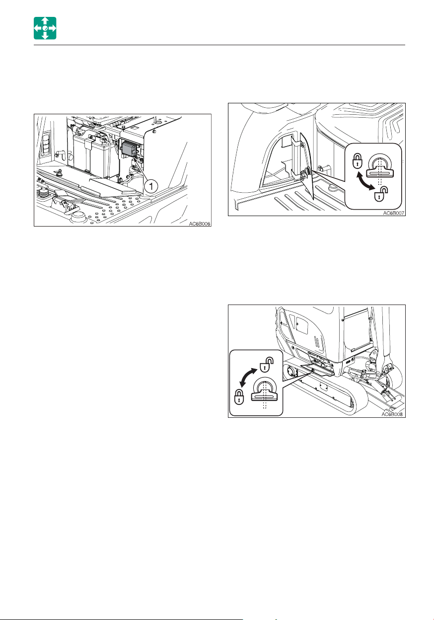
Controls
COVERS
FUSE BOX
This box is used to protect the electric
system from overcurrent.
Opening
1. Pull the fuse box cover (1) while pushing
the tab beside it.
Closing
1. Push in the fuse box cover (1) until the tab
clicks into place.
TOOL CASE
Opening
1. To unlock this case, insert the starter key
and turn it counterclockwise.
GREASE GUN HOLDER
Opening
1. To unlock this holder, insert the starter key
and turn it counterclockwise.
2-7
Page 58

Controls
COVERS
FUEL LID
When opening and closing the fuel lid, be
careful not to get your hands caught by
the lid.
For adding fuel, open this cover.
Opening
1. Insert the starter key and turn it
counterclockwise to unlock the fuel lid (1).
Closing
1. Close the fuel lid (1).
2. Insert the starter key and turn it clockwise
to lock the fuel lid (1).
FUEL FILLER PORT
• Do not smoke and keep away from heat
or flame while filling the fuel tank.
• Fill the fuel tank in a well ventilated
place, with the engine turned off.
• Clean up spilled fuel immediately.
• Do not fill the fuel tank to capacity.
Allow room for oil expansion.
• Securely tighten the fuel filler cap.
Opening
1. Open the fuel lid.
2. Turn the fuel cap (1) counterclockwise and
remove it.
Closing
1. Turn the fuel cap (1) it clockwise and close
it.
2. Close the fuel lid and lock it.
2-8
Page 59

Controls
COVERS
SIDE COVER
When opening and closing the side cover,
be careful not to get your hands or other
parts of your body caught by the cover.
Opening
1. Insert the starter key and turn it
counterclockwise to unlock the side cover
(1).
ENGINE HOOD
• Before opening the engine hood, be
sure to stop the engine. If a hand or tool
becomes trapped in the rotating or
moving part, serious injury could result.
• When opening or closing the engine
hood, be careful not to get your hands
or other parts of your body caught by it.
Opening
1. Insert the starter key and turn it
counterclockwise to unlock the engine
hood (1).
2. Push in the key hole (2) with your thumb
and open the engine hood (1).
2. Fully open the side cover (1) and secure it
with the stay (2)
Closing
1. Support the side cover (1) by hand and
release the stay (2).
2. Close the side cover (1).
3. Insert the starter key and turn it clockwise
to lock the side cover (1).
Closing
1. Close the engine hood (1) and press down
the edge of it until a click is heard.
2-9
Page 60

Controls
CAB
CAB
CAB DOOR
When getting on or off the cab, first open
the door all the way until it is secured in
the catch and check that it does not
move.
Open the door fully and press it against the
catch at the back of the door to secure it in
place.
The door must be locked when getting on or
off the machine and while in operation.
Locking and unlocking
2. Open the door fully and press it against
the cab to secure it in place.
Closing
1. Push the release lever (3) to the lower.
2. Close the released door.
EMERGENCY EXIT
Front window (excluding machines with a
front guard)
Insert the starter key and turn it.
Opening
1. Pull the knob (1) towards you and open
the door.
To open the door from inside the cab, hold
the door opener (2).
If you should become trapped inside the
cab, open the front window to get out.
2-10
Page 61

Controls
CAB
FRONT WINDOW
• Grasp the handles firmly with both
hands when opening and closing the
front window. Your head or hands may
get caught if it slips from your hands.
• When the front window is opened or
closed, it will come close to the head.
Be careful that the window does not
strike the head.
• When you open the front window, be
sure to lock it in place with the lock pins
on the left and right sides. The window
may fall if it is not locked in place.
5. Release your thumb from the knobs (2)
and then lift the front window (3) fully and
lock the front window with lock pin (4).
Closing
Opening
1. Park on a level surface and stop the
engine.
2. Set the safety lock lever to the locked
position.
3. Grasp the left and right handles (1) and
press the knobs (2) with your thumb to
release the lock.
4. Pull the front window (3) toward you and
lift while doing so.
When closing the front window slowly so
as not to hit your head. Lowering the
window abruptly may result injury or
damage the front window.
1. Grasp the left and right handles (1) and
press the knobs (2) with your thumb to
release the lock.
2. Pull down the front window (3) and while
doing so, slide it to the front and slowly
lower it.
2-11
Page 62

Controls
AG7B019
CAB
3. Release your thumb from the knobs (2)
and then press the front window toward
front and lock the front window with lock
pin (4).
LOWER FRONT WINDOW
Removing
SIDE WINDOW
Opening
1. Release the lock by turning the locking
screw (7) counterclockwise
2. Hold the catch (8) to disengage it and
open the side window.
3. Secure the side window by turning the
locking screw (7) clockwise.
Closing
1. Release the lock by turning the locking
screw (7) counterclockwise
2. Close the window until a click is heard,
and then secure the window by turning
the lock screw (7) clockwise.
1. Open the front window and stow it in the
ceiling.
2. Slowly lift the lower front window (4).
6
4
5
5
3. Hold the glass firmly, place it through the
guides (5) at the rear, and then set it on
the supports (6) to fasten it in place.
2-12
Page 63

Controls
CAB
EMERGENCY HAMMER (OPTIONAL)
An emergency hammer is installed to be
used to escape from the cab in an
emergency. When escaping, break the
windows with the hammer.
• When breaking the windowpane with a
hammer, take great care not to injure
yourself with the broken glass pieces.
• Remove the glass pieces from the window
sill so as not to cut yourself when
evacuating. Broken glass will fall from the
window, so be careful of your footing and
do not slip on the glass.
2-13
Page 64

Controls
SEAT AND SEAT BELT
SEAT AND SEAT BELT
SEAT (IF EQUIPPED)
Adjust and secure the seat.
3
1
AD6B017
(A) Adjusting the backrest angle
1. Sit up and sit back in the seat.
2. Set the backrest to the desired angle by
turning the handle (1).
(B) Fore-and-aft adjustment
1. Pull up the lever (2) and slide the seat
backward or forward to the desired
position for operation of machine.
2. Release the lever (2) at the desired
position to secure the seat.
Adjustment range: 10 positions, in 150
mm (5.9 in.)
(C) Adjusting according to operator’s
weight
1. Move the lever (3) to set it according to
the weight of operator.
Position of the lever (3)
Upper ...... Light weight operator
Middle ..... Medium weight operator
Lower ...... Heavy weight operator
2
2-14
Page 65

Controls
SEAT AND SEAT BELT
HIGH-BACK SEAT (IF EQUIPPED)
Adjust and secure the seat.
(C) Adjusting according to operator’s
weight
1. Turn the handle (3) until the display
indicates the weight of operator.
Adjustment range: 50 to 130 kg (110 to
287 lbs)
2. When adjusting for a weight lower than
the currently set weight, first turn the
handle (3) as far as it goes to cancel the
setting, then readjust.
(A) Adjusting the backrest
1. Sit up and sit back in the seat.
2. Pull up the lever (1), recline the backrest
by using the spring force. Release the
lever (1) at the desired angle to secure the
backrest.
(B) Fore-and-aft adjustment
1. Pull up the lever (2) and slide the seat
backward or forward to the desired
position for operation of machine.
2. Release the lever (2) at the desired
position to secure the seat.
Adjustment range: 10 positions, in 150mm
(5.9in.)
2-15
Page 66

Controls
SEAT AND SEAT BELT
SEAT BELT
Be sure to fasten the seat belt securely
before starting the engine.
Fastening the seat belt
1. Adjust the seat to the desired position for
operation, sit up and sit back in the seat.
2. Pull the seat belt to the desired length.
3. Make sure that the belt is not twisted and
then insert the tongue plate (A) into the
buckle (B) of the seat belt until you hear a
clicking sound as it locks in place.
4. Check if the belt is securely locked by
pulling it, and arrange the belt around your
waist.
Releasing the seat belt
1. Grasp the tongue plate (A) and press the
button (C) on the buckle (B).
The seat belt retracts back into its original
position.
2-16
Page 67

MEMO
2-17
Page 68

Controls
INSTRUMENT CLUSTER
INSTRUMENT CLUSTER
Once the starter switch is turned to ON, all lamps on the instrument cluster light up.
Then, the battery charge warning lamp (3) and the engine emergency lamp (1) start flashing.
The machine system is normal if the lamps turn off after the engine is started.
If any lamp is not lit when the starter switch is turned to ON, there is something wrong in the
machine. Consult your sales or service dealer.
WARNING LAMPS
IMPORTANT: If a warning lamp flashes
and an alarm is sounded, immediately
stop all operations and check the
corresponding component.
Refer to “If a warning lamp flashes” on
page 6-9.
1. Engine emergency lamp
This lamp flashes and an alarm sounds if
there is a problem with the engine or
charging system.
2. Engine oil pressure warning lamp
This lamp flashes and an alarm is sounded
if the lubricant oil pressure abnormally low
while the engine is running.
3. Battery charge warning lamp
This lamp flashes and an alarm is sounded
if a problem rises in the charging system
while the engine is running.
4. Coolant temperature warning lamp
This lamp flashes and an alarm is sounded
if the engine coolant temperature
becomes abnormally high while the engine
is running.
2-18
Page 69

Controls
INSTRUMENT CLUSTER
5. Fuel level warning lamp
This lamp turns on if the fuel level
becomes low while the starter switch is in
the ON position.
INDICATORS
6. Glow lamp
This lamp goes out when the engine
preheating is completed.
7. Travel speed lamp
This lamp turns on when the travel speed
button is set to the 2nd (high) speed.
METERS
8. Water temperature gauge
Indicates the temperature of the engine
coolant water.
The LED should be within the green range
during machine operation.
The red range indicates overheating.
9. Fuel Gauge
Indicates the amount of fuel in the tank.
Be sure to top off the tank before running
out of fuel.
2-19
Page 70

Controls
INSTRUMENT CLUSTER
MULTI-DATA DISPLAY
10. LCD (liquid crystal display)
It displays various data on hour meter,
trip meter and the machine.
Home screen
1. Key function display
The key function display changes
depending on the screens (Home,
Menu and each setting)
For actual operation, use the buttons,
“A”, “B” and “C”, located beneath
each symbol. Refer to “Operating
each key” on pages 2-20 to 2-25.
2. Hour meter/Trip meter
• Hour meter
Displays the total engine running time
in hours.
The rightmost digit indicates tenths of
hours (6 minutes).
Set the inspection and maintenance
intervals according to the time
displayed on the hour meter.
4. Alarm indicator lamp
The clock symbol appears when the
alarm function is turned on.
Refer to “Alarm setting” on page 2-24.
5. Auxiliary 3rd hydraulic pressure
warning lamp (If equipped)
This lamp lights up and an alarm
sounds if the fixed side (left “e”)
pressure of the auxiliary 3rd drops
abnormally while the engine is running
or if the quick-hitch is being removed
or installed.
6. Highland mode indicator lamp
(If equipped)
When the highland mode is selected
This mode is used to reduce the
engine load due to the hydraulic pump.
When the machine is operated at a
high-altitude site, the engine output is
decreased due to thin air. In such
cases, the hydraulic horse power is
automatically adjusted to prevent the
engine from stalling. The machine
automatically enters this mode if the
altitude detected by the bolometric
sensor is 800 m (2622 ft) or more.
7. Lift overload warning indicator lamp
This lamp turns on when the lift
overload warning switch is turned on.
• Trip meter
Three patterns of desired operating
hours can be displayed.
Refer to “Trip meter display” on page
2-21.
3. Time display
Displays the time set.
Refer to “Time setting” on page 2-24.
2-20
Page 71

Controls
INSTRUMENT CLUSTER
FUNCTION OF EACH KEY
The functions are as below in the Home
screen. The different functions appear in the
other screens.
A. Stopping alarm
Pressing the (A) key stops alarm.
B. Work light/meter switching
· Pressing the (B) key turns on or off the
work light.
· Pressing and holding the (B) key for two
seconds or more each time the display
changes as follows:
1. Hour meter
2. Trip meter 1
4. Trip meter 3
5. Returns to the hour meter
C. Menu/trip meter reset
· Pressing the (C) key switches to the
Menu screen.
· Pressing and holding the (C) key for
three seconds or more while the trip
meter is displayed returns the trip meter
to “0”.
3. Trip meter 2
2-21
Page 72

Controls
INSTRUMENT CLUSTER
MENU SCREEN
Press the (A) key to proceed to the screen
selected by the bar.
Press the (B) key to move the selection bar.
Press the (C) key to return to the Home
screen.
• DATA
Shows the coolant temperature and the
trip meter for inspection and
maintenance.
Unlike the trip meter displayed on the
Home screen, data items on the engine
oil, hydraulic oil and coolant are included
so that you can use them as a guideline
for replacement.
• SETTING
Time, alarm and contrast can be set.
2-22
Page 73

Controls
INSTRUMENT CLUSTER
DATA SCREEN (DATA)
Press the (A) key to proceed to the screen
selected by the bar.
Press the (B) key to move the selection bar.
Press the (C) key to return to the Menu
screen.
• Trip meter (TRIP METER) for
maintenance
The trip meters for the engine oil,
hydraulic oil or coolant are displayed.
• Coolant temperature (WATER TEMP)
Displays the coolant temperature in
Celsius °C or Fahrenheit °F.
Press the (C) key to return to the Data
screen.
Press and hold the (A) key for at least five
seconds resets the selected trip meter to
“0”.
Press the (B) key to move the selection
bar.
Press the (C) key to return to the DATA
screen.
2-23
Page 74

Controls
INSTRUMENT CLUSTER
SETTING SELECTION SCREEN (SETTING)
Press the (A) key to proceed to the screen
selected by the bar.
Press the key (B) to move the selection bar.
Press the (C) key to return to the Menu
screen.
• Time setting (CLOCK)
The time to be displayed on the Home
screen can be set here.
a. When the selection bar is at CLOCK,
press the (A) key to proceed to the time
setting screen (CLOCK SET).
b. Pressing the (A) key in this screen moves
the selection bar and flashes the figures
on the bar.
Setting range: hours, 1 to 24; minutes,
00 to 59
c. Press the (B) key to increase the number
value selected.
Press and hold the (B) key to rapidly
increase the number value selected.
d. Press and hold the (A) key for at least
two seconds to complete the setting
and to return to the Setting Selection
screen.
e. Press the (C) key cancels editing and to
return to the Setting Selection screen.
• Alarm setting (ALARM)
Five patterns of alarm setting are
available.
Alarm function can be set to on or off
within the five patterns.
a. When the selection bar is at ALARM,
press the (A) key to proceed to the alarm
setting screen (ALARM SET).
b. Press the (A) key in this screen to place
a checkmark in the box at the left of the
setting bar. Press the (A) key again to
remove the checkmark.
The alarm setting cannot be changed
only by placing or removing a
checkmark.
c. Press and hold the (A) key for at least
two seconds to complete the setting
and to return to the Setting Selection
screen.
Be sure to perform the above operation
when you wish to set the alarm.
A clock symbol is displayed on the
Home screen.
d. Press the (B) key to move the selection
bar.
e. Press and hold the (B) key for at least
three seconds to enter the alarm time
setting mode.
f. Press the (C) key to cancel editing and
to return to the Setting Selection screen.
Checked ............On
Unchecked ........Off
2-24
Page 75

Controls
INSTRUMENT CLUSTER
• Alarm time setting mode
Sets the time for alarm.
a. Select the item to be set in the alarm
setting screen (ALARM SET).
b. Press and hold the (B) key for at least
three seconds to enter the alarm time
setting mode.
c. Press the (A) key in this screen to move
the selection bar and to flash the figures
on the bar.
Setting range: hours, 1 to 24; minutes,
00 to 59
d. Press the (B) key to increase the number
value selected.
Press and hold the (B) key to rapidly
increase the number value selected.
e. Press and hold the (A) key for at least
two seconds to complete the setting
and to return to the Setting Selection
screen.
f. Press the (C) key to cancel editing and
to return to the Setting Selection screen.
• Contrast setting (CONTRAST)
Adjust the LCD contrast.
a. When the selection bar is at CONTRAST,
press the (A) key to proceed to the
contrast setting screen (CONTRAST).
b. To increase contrast, press the (B) key.
The bar advances to the right.
Press and hold the (B) key to rapidly
advance the bar.
Once the bar reaches the right end
(highest contrast), it returns to the left
end (lowest contrast).
c. Press and hold the (A) key for at least
three seconds to complete the setting
and to return to the Setting Selection
screen.
d. Press the (C) key to cancel editing and
to return to the Setting Selection screen.
The changes made to the setting are
reflected, but they will be removed when
the starter switch is turned off.
2-25
Page 76
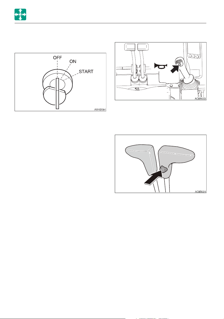
Controls
SWITCHES
SWITCHES
STARTER SWITCH
IMPORTANT: Do not repeatedly switch
the key from OFF to ON and ON to OFF
over a short period. Doing so will cause
engine breakdown.
OFF ......... Position for stopping the engine
and inserting or removing the key.
ON .......... Position in which the engine is
running. At this position, all the
electrical equipment is functional.
When the coolant temperature is
too low, the engine is
automatically preheated.
START ..... Position for starting the engine.
When the key is released, the
switch automatically returns to the
ON position.
HORN BUTTON
Press the button situated on the right
operating lever to blow the horn.
TRAVEL SPEED SWITCH
Press this switch to set the travel speed to
2nd (high) speed. Press it again to return to
1st (low) speed.
2-26
Page 77

Controls
SWITCHES
WIPER SWITCH
IMPORTANT: If no washer fluid is
discharged, do not operate the washer.
Doing so may damage the pump.
IMPORTANT: Operating the wiper with no
moisture on the windshield will scratch
the glass. Use water or washer fluid when
operating the wiper.
IMPORTANT: In cold climates, the wiper
blade may freeze to the glass. Operating
the wiper forcibly may damage the wiper
motor.
O ............. Off
I ............. Wiper operates
PUSH ...... Sprays washer fluid when
pressed. Stops when released.
SECOND AUXILIARY HYDRAULIC SWITCH
Refer to “Second auxiliary hydraulic switch”
on page 2-44.
THIRD AUXILIARY HYDRAULIC SWITCH AND BUTTON
Refer to “Third auxiliary hydraulic switch and
button” on page 2-44.
2-27
Page 78

Controls
SWITCHES
OVERLOAD WARNING SWITCH (IF EQUIPPED)
If the overload is not removed after the
overload warning horn is sounded, the
machine may tip over. If the horn starts
sounding, stop operating the machine
and lighten the load.
If a weight greater than the lifting capacity is
applied or lifted, the overload warning device
is activated and the horn sounds. (When the
overload warning switch is turned on.)
OFF ......... Off
ON .......... On
2-28
Page 79

Controls
LEVERS AND PEDALS
LEVERS AND PEDALS
SAFETY LOCK LEVER
• Before standing up from the operator’s
seat to, for example, adjust the
operator’s seat, lower the working
equipment to the ground, raise the
safety lock levers to engage the lock
and stop the engine. If any controls
should be accidentally touched when
the safety lock levers is lowered
(unlocked), the machine will suddenly
move and cause serious injury or death.
• Note that the dozer blade, boom swing
and auxiliary hydraulic controls cannot
be locked, even when the safety lock
lever is set to the locked position.
Do not carelessly touch these controls.
• Be careful not to touch the operating
levers when raising or lowering the
safety lock lever.
• Before leaving the operator’s seat, lower
the working equipment to the ground,
raise the safety lock levers to engage
the lock and stop the engine. Also, be
sure to remove the key, lock the door
and covers, take it with you and store it
in a specified place.
THROTTLE LEVER
This controls the engine speed.
(A) .......Low idling
(B) ......Maximum speed
This device is for locking the hoe attachment,
slewing and traveling.
When the lever is raised, the lever stand
springs up and the controls are locked.
2-29
Page 80

Controls
LEVERS AND PEDALS
OPERATING LEVERS
• Before starting operation, carefully
check which lever pattern you are going
to use.
• It is described using the ISO pattern in
this manual.
Use these levers to operate the boom, arm,
bucket and upperstructure.
Refer to “Lever pattern” on pages 3-6 and
3-7.
Refer to “Operating the working equipment”
on pages 3-16 and 3-17.
BLADE LEVER
Use this lever to operate the dozer blade.
(A) .......Blade up
(B) ......Blade down
Refer to “Operating the dozer blade” on
page 3-17.
2-30
Page 81

Controls
AD6B031
AD6B032
LEVERS AND PEDALS
TRAVEL LEVERS/PEDALS
• Before operating the travel levers/
pedals, make sure that the dozer blade
is to the front of the operator’s seat.
Remember that when the dozer blade is
to the rear of the operator’s seat, the
travel levers/pedals must be operated in
the reverse direction from when it is to
the front.
• Do not rest your foot on the pedal
unless operating it for traveling. If the
pedal is accidentally stepped while
working, the machine may suddenly
move and cause serious injury or death.
BOOM SWING PEDAL
Keep the pedal cover to the locked
position when not using the pedal.
Stepping on a pedal accidentally when it
is not locked may cause accidents.
B A
Use this pedal to operate the boom swing.
(A) .......Boom swing right
(B) ......Boom swing left
Refer to “Operating the boom swing” on
page 3-17.
Pedal lock
Use these levers/pedals to move forward or
backward and to change directions. Fold the
pedals when not being used.
Refer to “Operating the travel levers” on
page 3-12.
Set the pedal cover over the pedal to lock it.
Open the pedal cover from the pedal to
unlock it.
2-31
Page 82

Controls
AD6B033
AD6B032
LEVERS AND PEDALS
AUXILIARY HYDRAULIC PEDAL
Keep the pedal cover to the locked
position when not using the pedal.
Stepping on a pedal accidentally when it
is not locked may cause accidents.
A
This pedal controls the flow of the oil in the
auxiliary hydraulic circuit.
(A) .......Hydraulic oil flows to left auxiliary
hose.
(B) ......Hydraulic oil flows to right auxiliary
hose.
Refer to “Auxiliary hydraulic lines” on page
2-42.
B
SELECTOR LEVER
This lever is used to change the crawler
width. The operation of the dozer blade
cylinder and the span cylinder is switched
with this lever.
1. Change the crawler width by moving the
blade lever while depressing this lever.
Pedal lock
Set the pedal cover over the pedal to lock it.
Open the pedal cover from the pedal to
unlock it.
2-32
Page 83

MEMO
2-33
Page 84

Controls
ACCESSORIES
ACCESSORIES
HEATER
• Always be sure to allow sufficient
ventilation.
• Do not place combustible or explosive
objects near the air outlets.
Heater fan switch
............ Low
Neutral .... OFF
............ High
Outlets
Move the louver up and down or left and
right to adjust the air flow direction and
amount.
Ventilation/Circulation lever
Use this lever to switch between Ventilation
and Circulation.
...Full ventilation: For heating with
ventilation. Intake of
external air. Defrosting
the windows.
........ Circulation: Quick heating or when
external air is dirty.
2-34
Page 85

Controls
ACCESSORIES
Heater valve
Coolant circulates in the heater even when
the heater switch is turned off.
When the heater is no longer needed, stop
coolant circulation as follows.
IMPORTANT: Use the valve (1) either fully
open or fully closed.
Cooling water could leak when the valve
is partly opened.
1. Park the machine on a level surface and
stop the engine.
2. Open the engine hood.
3. Turn the valve (1) clockwise until it stops to
close it.
Filters
Clean the filters immediately after operating
in dusty places.
If the filters are clogged, the air flow is
reduced and a booming sound is heard from
the heater unit.
Refer to “Cleaning the air filters” on page
5-39.
2-35
Page 86

Controls
ACCESSORIES
CUP HOLDER
• Drinks may be spilled due to vibration
when the machine is operating or
traveling. Be particularly careful not to
burn yourself with hot drinks.
• Note that the cigarette lighter or other
electric parts may be damaged if drinks
are spilled on them.
Pull out the cup holder towards you to use it.
Push in the holder for storage after use.
INTERIOR LIGHT
IMPORTANT: The battery capacity
decreases if the interior light is left on for
a long time when the engine is stopped.
OFF ....Remains off all the time.
ON .....Lights up all the time.
INSIDE REAR VIEW MIRROR (CAB)
Adjust the rear view mirror to have a better
rear view.
2-36
Page 87

Controls
ACCESSORIES
POWER SOCKETS
Use only those electric products which
comply with the specifications of these
sockets.
For beacon
ARMREST
Adjusting the height
1. Loosen the lock by turning the bolts (1)
counterclockwise.
2. Set the armrest to your desired position,
and turn the bolts (1) clockwise to lock the
armrest.
Use these sockets to connect the power
supply. When using, be careful not to exceed
12V/5A.
To use, open the cap (1).
2-37
Page 88

Controls
ACCESSORIES
RADIO (FOR CAB)
CAUTIONS ON USE
• To ensure safe operation of the machine, always be sure to keep the volume of the
radio down to a level where you can easily hear sounds from outside the machine.
• Do not use the radio for a long time when the engine is stopped. Doing so will drain
the battery and make it difficult or impossible to restart the engine.
• Be careful not to allow water or other liquids to come into contact with the radio.
Otherwise, it may result in malfunction.
NAMES OF COMPONENTS
(1) POWER button
Use this button too turn on or off the
radio.
(2) LCD
Displays the time/the receiving frequency
and the operation mode.
(3) Display button (DISP)
Pressing this button while the frequency
is displayed on the LCD changes the
display to the clock. Pressing the button
again returns to the frequency. If the
button is not pressed for five seconds,
the display returns to the frequency.
(4) Auto store/Auto seek station (AST)
Press this button to automatically assign
receivable radio stations to preset
buttons (1 to 6).
(5) Tuning button (TUNE
Press and hold this button (
one second or more to start seeking the
receivable stations. The seeking stops
when a station is found. To cancel tuning
halfway, press the button again.
Pressing the TUNE button
seeking stations with higher frequency.
Pressing the TUNE button
seeking stations with lower frequency.
The frequency changes as either button
is pressed in one second intervals.
2-38
)
starts
starts
or ) for
Page 89

Controls
ACCESSORIES
(6) Preset buttons (1 to 6) (PRESET
STATION)
Each button can store three FM stations
(FM1, FM2, FM3) and one MW (AM)
station. For how to set these buttons,
refer to “Presetting stations”.
(7) Band button (BAND)
Pressing this button changes the band
from FM1 to FM2, FM3 and MW (AM) in
this order. The received band and its
frequency appear on the display.
(8) VOL buttons
Use these buttons to control the sound
volume. Press the button
the volume and the button
decrease the sound volume. Press and
hold each button to continuously
increase/decrease the volume.
(9) Clock zero set button (ZERO)
Use this button to set the minute to “00”
when it is between “55” to “59” or “01”
to “05”.
The LCD returns to the frequency display
if no more operation is performed for five
seconds.
(10) Auxiliary input select button (AUX)
Pressing this button changes the input
source to the external device connected
to the AUX-IN (13) jack. The display of
“AUX” appears on the LCD. Pressing the
button again returns to the radio.
to increase
to
(11) Auxiliary input jack (AUX-IN)
Use this jack to connect an external
audio source such as a portable music
player. Pull off the rubber cap and
connect the output terminal (headphone
jack) of the portable player to the AUX-IN
with the stereo mini-plug (35 mm) cord.
Be sure that jack is closed with the
rubber cap when not in use.
Playing the radio
1. Turn the ignition key to the ACC or ON
position, and then press the power button
(1) to turn on the radio.
2. Select the band, FM or MW (AM) by
pressing the BAND button.
3. Select the station with the preset button or
the tuning button, and adjust the volume
with the volume button.
4. To turn off the radio, press the power
button.
Selecting a station-auto select
Press and hold the TUNE button
second or more to start seeking stations in
the higher frequencies direction. Press and
hold the TUNE button
more to start seeking stations in the lower
frequencies direction. The radio will stop
seeking when it finds an receivable station
and start playing.
Selecting a station-manual select
The selection can be done manually. Press
the tune
higher frequencies. Press the tune
to seek stations with lower frequencies.
button to seek stations with
for one second or
for one
button
2-39
Page 90

Controls
ACCESSORIES
Presetting stations
1. Press the BAND button to select a band
(MW (AM) or FM), and then select the
station by pressing the TUNE button for
seeking.
2. To assign the selected station to a preset
button, press and hold the button to be
assigned for one second or more. The
number of the preset button appears on
the LCD.
3. For more stations to preset, repeat the
steps (1) and (2) above.
• If the preset button on which a station
has been assigned is pressed and held
for one second or more, the preset
information will be modified.
• If the stored information is erased during
battery replacement on the vehicle,
assign the stations again to the preset
buttons.
• Each preset button can store three FM
stations (one from each FM1, FM2, FM3)
and one AM station.
Auto storing (AST)
Press the AST button while playing the radio.
The radio automatically starts seeking the
receivable stations within the band currently
selected and assign each preset button (1 to
6) a station.
Note: The previous stations stored will be
cleared (cancelled) by the auto storing. If the
station stored in the preset button is not
desirable, try to preset the station manually.
Auxiliary input (AUX)
• Connect a portable audio player and listen
to your favorite music.
• Plug a patch cord (without resistor) into the
headphone jack of the audio player.
• Plug a stereo mini plug (3.5 mm) into the
AUX-IN jack on the radio.
• To listen to an external portable audio
player, press the AUX button. (The “AUX”
display appears on the LCD and the
frequency display is changed to the clock
display.)
• To return to the radio, press the AUX
button again.
• When connecting, adjust the sound volume
level of the audio player so that it is same
as that of the radio.
• Adjust the sound volume of the audio
player by using the volume control buttons
on the radio.
• Do not connect a device with a larger
output compared with a portable audio
player.
Setting the clock
• If a frequency is displayed on the LCD,
press the AUX button (auxiliary input) to
display the clock.
• Use the tune
Use the tune
• To set the minute digits to “00” when they
are from “55” to “59” or from “01” to “05”,
press the ZERO button.
2-40
button to set the minute.
button to set the hour.
Page 91

Controls
ACCESSORIES
Resetting
If there are any problems, such as the
abnormal display of frequency or failure of
selection, reset the radio by pressing the “4”
button while pressing the AST button and
the AUX button together. Then, “JP” and the
clock display appear on the LCD, indicating
that the radio is turned off. Note that the
memory stored in the preset button is
cleared.
SPECIFICATIONS
Power source: .... 12/24 VDC (negative
ground)
Maximum power consumption:
........................... 3A or less (at max. volume,
24 V)
Maximum output power:
........................... 16 W + 16 W (4Ω) (at 28.8
VDC input)
5W+5W (4Ω) (at 14.4 VDC
input)
Rated output power:
........................... 12 W + 12 W (10%
distortion, 4Ω) (at 28.8
VDC input)
3.5 W + 3.5 W (10%
distortion, 4Ω) (at 14.4
VDC input)
Dimensions: ........ 178 (W) x 50 (H) x 65 (D)
mm (excluding protrusions)
Receiving frequency:
........................... MW (AM) 531 to 1602 kHz
(Europe, Asia), 530 to
1710 kHz (North, Central
and South America)
FM 87.5 to 108 MHz
(Europe, Asia), 87.9 to 108
MHz (North, Central and
South America)
Practical sensitivity:
........................... MW (AM) 32 dB or less
(S/N 20 dB)
FM 12 dB or less (S/N 30
dB)
S/N ratio: ............ MW (AM) 40 dB or more
FM 50 dB or more
AUX-IN: .............. Stereo mini jack (3.5 mm);
rated input, 90 mV; 20 kΩ
impedance
Note: Specifications and dimensions may be
changed without notice.
2-41
Page 92

Controls
ACCESSORIES
AUXILIARY HYDRAULIC LINES
First / second auxiliary hydraulic lines (If equipped)
Third auxiliary hydraulic lines (If equipped)
Oil may spurt out if pipes disconnected
before releasing the pressure in the
hydraulic system.
• Immediately after the engine is stopped,
press each auxiliary hydraulic pedal and
second auxiliary switch several times to
release the pressure from the auxiliary
hydraulic circuit.
• Slowly loosen the air bleeding plug to
relieve the internal pressure of the
2-42
Page 93

Controls
ACCESSORIES
hydraulic oil tank.
• When disconnecting hoses, stand to the
side and loosen them slowly to
gradually release the internal pressure
before removing.
These lines deliver the hydraulic oil necessary
for operating a hydraulic breaker, crusher or
other attachments.
(1) .......First auxiliary hydraulic lines
(2) .......Second auxiliary hydraulic lines
(3) .......Third auxiliary hydraulic lines
Stop valve
(S) : Closed
(O) : Open
Connecting the hydraulic circuits
To connect the attachment hydraulic lines,
observe the following procedures:
1. Release the pressure remaining in the
lines, and then close the stop valve.
Refer to “Releasing the residual pressure”
on page 2-43.
2. Remove the plugs.
3. Connect the attachment hydraulic lines to
ports (a/c) and (b/d). When installing a
hydraulic breaker, connect the supply
circuit to the port (a) and the return circuit
to port (b).
4. Open the stop valves. When installing a
hydraulic breaker, open the selector valve
(1). Refer to “Selector valve (Option)” on
page 2-44.
5. When connecting is complete, purge air
from the hydraulic lines.
a. Start the engine and run it at a low idle
speed with no load for 10 minutes.
b. With the engine running in low idle,
operate the auxiliary hydraulic switches
repeatedly (approx. 10 times) to purge
air from the hydraulic lines.
c. Stop the engine and wait for at least 5
minutes until bubbles escape from the
hydraulic oil in the tank.
IMPORTANT: Follow the procedures for
purging air as instructed by the
attachment manufacturer, if applicable.
6. Check for oil leaks.
Disconnecting the hydraulic circuits
1. Release the pressure remaining in the
lines, and then close the stop valve.
Refer to “Releasing the residual pressure”
on page 2-43.
2. Disconnect the lines from the ports (a/c)
and (b/d).
3. Install the plugs.
Operating
A
B
AD6B033
Press this pedal to control the flow of the oil
in the auxiliary hydraulic lines.
(A) .......Hydraulic oil flows to left auxiliary line
(a).
(B) ......Hydraulic oil flows to right auxiliary line
(b).
Releasing the residual pressure
After the auxiliary hydraulic circuits have
been used, pressure remains in the circuits.
This is called the residual pressure. Release
this residual pressure before disconnecting
the lines.
1. When the engine is stopped, depress the
auxiliary hydraulic pedals from side to side
several times.
2-43
Page 94

Controls
ACCESSORIES
Selector valve (Option)
Open ....... When using a hydraulic breaker
(1-way flow)
Closed ..... When using a reversible
attachment (2-way flow)
Change the direction of the hydraulic oil flow
by opening or closing the selector valve (1)
on the machine body.
Second auxiliary hydraulic switch
Slider switch
(Proportional control)
Proportional control allows for slow-to-fast/
fast-to-slow movement of attachment.
Example: If you move the slider switch half
way, the attachment will move at
approximately one-half the speed.
Third auxiliary hydraulic switch and
button
The third auxiliary hydraulic lines are normally
used to control the “quick attachment”
installed to connect/disconnect the bucket.
When the safety lock lever is released after
the engine is started, hydraulic oil flows into
the pipe (e). This allows the pressure in the
(e) side to increase and to prevent the pin
inserted on the bucket from coming out. If
the pressure in the (e) side drops, the alert
that the bucket may come out is indicated by
the warning lamp and the alarm. For a safety
reason, the bucket can be disconnected only
when the button (1) and the switch (2) are
pressed at the same time. When they are
pressed, the hydraulic oil flows into the line (f)
to increase the pressure there. As the result,
the pin on the bucket comes out and the
bucket is removed from the machine.
Move this switch to control the flow of the oil
in the second auxiliary hydraulic lines.
(C): .... Hydraulic oil flows to the left auxiliary line (c).
(D): .... Hydraulic oil flows to the right auxiliary line (d).
Releasing the residual pressure
Refer to “Accumulator” on page 2-46.
2-44
Page 95

Controls
AD6C013
AD6C014
ACCESSORIES
Adjusting the stroke of auxiliary hydraulic
pedal
When a breaker is used, the pedal stroke
must be adjusted so as not to activate the
right auxiliary hydraulic line even if the B side
of the pedal is accidentally depressed.
When a general attachment is used, the
pedal stroke must be readjusted. Adjust it so
that the right auxiliary hydraulic line is
activated when the B side of the pedal is
depressed.
When using a hydraulic breaker
(1-way flow)
A
B
2
1
Make sure that the auxiliary hydraulic
1.
pedal is in the neutral position.
2. Loosen the lock nut (1).
3. Loosen the adjustment bolt (2) until it
touches the pedal.
4. Fasten the lock nut (1) to secure the
adjustment bolt (2).
When using a reversible attachment
(2-way flow)
A
B
2
1
1. Loosen the lock nut (1) and screw in the
adjustment bolt (2) to the end.
2. Depress the B side of the auxiliary
hydraulic pedal to the stroke end and hold
its position.
3. Loosen the adjustment bolt (2) until it
touches the pedal.
4. Fasten the lock nut (1) to secure the
adjustment bolt (2).
2-45
Page 96

Controls
ACCESSORIES
ACCUMULATOR (IF EQUIPPED)
Operating the machine with an
accumulator
Be sure to handle the high-pressure
nitrogen gas enclosed in the accumulator
with care. If handled incorrectly, it could
explode and cause serious injury. Strictly
observe the following precautions:
• Do not disassemble.
• Do not allow flame near or throw it into
a fire.
• Do not drill, weld or fuse.
• Do not subject it to physical shock such
as hitting, rolling or dropping.
• Before disposing of the unit, the sealed
gas must be drained. Contact a
Takeuchi service agent for help.
6. Move the auxiliary 2nd switch several
times to release the residual pressure in
the circuitry. (If equipped)
7. Move all the control levers and pedals
several times in all directions to release the
pressure from the working equipment
circuitry.
8. Raise the safety lock lever to engage the
lock.
For a machine with an accumulator, the
residual pressure in the auxiliary hydraulic
circuit or the working equipment circuit can
be released even after the engine is stopped.
Releasing residual pressure
Residual pressure refers to the pressure that
remains in the hydraulic circuit after the
operation. Release the residual pressure as
necessary by using the following steps.
Perform the residual pressure releasing
within 10 minutes after the engine stopping.
1. Return the throttle lever to idle the engine
at low speed.
2. Lower the bucket and dozer blade to the
ground.
3. Check that the safety lock lever is in the
released position.
4. Stop the engine.
5. Turn the starter switch to the ON position.
Lowering the boom when the engine has
stopped
Perform this operation within 10 minutes
after the engine stopping.
1. Check that the safety lock lever is in the
released position.
2. Check that the starter switch is in the ON
position.
3. Slowly push the operating lever forward to
lower the boom.
2-46
Page 97

OPERATION
3-1
Page 98

OperatiOn
BEFORE STARTING OPERATION
BEFORE STARTING
OPERATION
GETTING ON OR OFF THE MACHINE
• Do not jump on or down from the
machine. Never attempt to get on or off
the moving machine.
• When getting on or off the cab, first fully
open the door to the locked position
and check that it does not move.
WALK-AROUND INSPECTION
Perform the walk-around inspections once a
day before starting the engine for the first
time that day.
Refer to “MAINTENANCE, Walk-around
inspection”, on pages 5-16 and 5-17.
DAILY INSPECTION
Perform the daily inspections once a day
before starting the engine for the first time.
Refer to “MAINTENANCE, Daily inspection”,
on pages 5-18 to 5-23.
• Climb up/down the steps holding the
handrail to support your weight in a
three point secure stance (hand and
feet).
• Never use the safety lock lever or
control levers as hand holds.
3-2
Page 99

OperatiOn
STARTING AND STOPPING THE ENGINE
STARTING AND STOPPING
THE ENGINE
BEFORE STARTING THE ENGINE
1. Adjust the seat for a comfortable operating
position.
2. Fasten the seat belt.
3. Check that the safety lock lever is in the
locked position.
5. Insert the key into the starter switch, turn it
to the ON position, then perform the
following inspections:
· All warning lamps flash for one second
and an alarm is sounded for ten
seconds. The meters also start
functioning. After two seconds, only the
battery charge warning lamp (3), the
engine oil pressure warning lamp (2) and
the engine emergency lamp (1) start
flashing, and the other lamps turn off.
· Press the light switch to check that the
boom light, front light and meter lights
turn on.
If a lamp does not light or the alarm is not
sounded, the bulb may be burnt out or a
wire may be damaged. Ask a Takeuchi
service agent for repair.
AD6D003
4. Check that all levers and pedals are in the
neutral position.
3-3
Page 100

OperatiOn
STARTING AND STOPPING THE ENGINE
STARTING THE ENGINE
• Clear all personnel from the work area.
• Sound the horn to warn people around
the machine.
IMPORTANT: Do not run the starter motor
for more than 15 consecutive seconds. If
the engine fails to start, wait for 30
seconds, and then try again to start the
engine.
Normal starting
1. Pull the throttle lever to the middle
position.
Starting in cold climates
Never use starting fluid on this engine, as
the starting fluid could cause an
explosion.
1. Pull the throttle lever to the middle
position.
2. Turn the starter key to the START position
and start the engine.
3. Once the engine starts, release the key.
The key automatically returns to the ON
position.
4. Check that the warning lamps are off.
5. Return the throttle lever and warm up the
engine.
Refer to “Warming up the engine” on page
3-5.
2. Turn the starter key to the ON position,
and confirm that the glow lamp is on. (The
glow lamp stays lit for up to three seconds
when the coolant temperature is 5°C
(41°F).)
3. After the glow lamp goes out, turn the key
to the START position to start the engine.
4. Once the engine starts, release the key.
The key automatically returns to the ON
position.
5. Check that the warning lamps are off.
6. Return the throttle lever and warm up the
engine.
Refer to “Warming up the engine”.
3-4
 Loading...