

Page 1

CycleavePCRTM O157 (VT1/VT2) Detection Kit Ver.2.0
Cat.#CY203
v.0607
Table of contents
I. Description...............................................................................2
II. Kit Components.........................................................................3
III. Reagents and Instruments Required..........................................3
IV. Storage......................................................................................3
V. Cautions....................................................................................4
VI. Protocols....................................................................................4
VI-1. Sample preparetion......................................................5
VI-2. Setting of Smart Cycler® II System...............................5
VI-3. Reaction mixture ........................................................7
VI-4. Display of results........................................................9
VI-5. Judgement..................................................................11
VII. Trouble Shooting......................................................................15
VIII. Reference.................................................................................16
IX. Related products.......................................................................17
URL:http://www.takara-bio.com
TAKARA BIO INC.
1
Page 2

CycleavePCRTM O157 (VT1/VT2) Detection Kit Ver.2.0
Cat.#CY203
v.0607
I. Description:
Enterohemorrhagic E. coli (EHEC) such as O157:H7 is a class of pathogenic
causes hemorrhagic colitis with accompanying melena and severe abdominal pain, and in
addition, hemolytic uremic syndrome. These serious symptoms are caused by verotoxin, a
cytotoxin produced by EHEC. It has been pointed out that in detection of EHEC, an assay
method of accurately and promptly determining if there are these verotoxin genes or not is
important.
This Kit is for real-time PCR assay to detect, in combination with a thermal cycler for real time
PCR, Smart Cycler® II System*1 (Cepheid), verotoxin genes (VT1 and VT2 genes) which cause
EHEC-related food poisoning. PCR is a technique for amplifying specifically the fragments of
the genes of interest in a short period of time using a trace amount of DNA as template. The
cycle comprising three steps of denaturation, primer annealing and extension with DNA
polymerase are repeated, thereby amplifying the gene fragments of interest up to 106-fold in
quite a short period of time.
By utilizing Smart Cycler® System, the amplification process can be real-time monitored.
As this kit uses Takara’s PCR enzyme efficient for Hot Start PCR,
non-specific amplification deriving from mispriming or from primer-dimers before thermal
cycling can be avoided and it achieves highly sensitive detection.
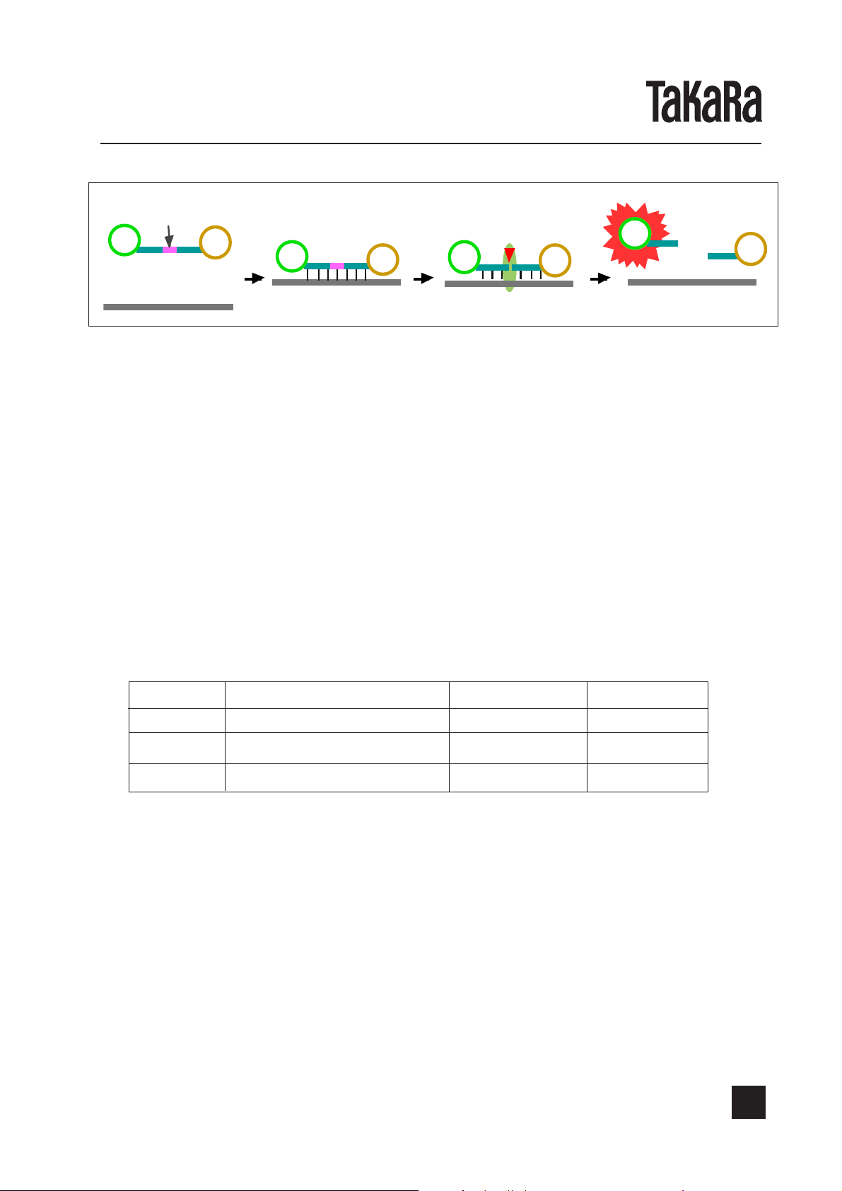
This kit employs Cycling Probe Technology(CPT)*2 for detection, which is a high-sensitive
detection method utilizing a combination of chimera probe, composed of RNA and DNA, and
RNase H. The specific sequence of target gene to be amplified can be detected efficiently
during or after amplification by this method. The 5' end of the probe is labeled with a fluorescent substance and the 3' end is labeled with a quencher, which quenches the fluorescence
emitted from the fluorescent substance at the 5' end. As long as this probe remains intact, no
strong fluorescence can be emitted because of the quenching function. When this probe forms
a hybrid with the complementary sequence of amplified product, RNase H specifically cuts the
RNA region of this probe, resulting in emission of strong fluorescence. By measuring the
intensity of emitted fluorescence, the amount of amplified product can be monitored.
Version 2.0 achieves higher specificity by improving probes.
This Kit incorporates the FAM labeling probe for detecting VT1 and the ROX labeling probe for
detecting VT2. It also contains an internal control and the TET labeling probe for detecting the
internal control. Simultaneous monitoring of three wavelengths with Smart Cycler® II System
requires only one tube to distinguish VT1 from VT2. This Kit also is able to monitor a false
negative reaction through the use of internal control. The real-time detection with this Kit does
not require electrophoresis and the detection result can be obtained quickly (in about 30
minutes).
Takara Ex Taq
E. coli
TM
which
R-PCR,
*1: Smart Cycler® System is a registered trademark of Cepheid.
*2: Cycling Probe Technology and DNA-RNA-DNA chimeric nucleic acid technology are
licensed by ID Biomedical Corporation.
2
TAKARA BIO INC.
URL:http://www.takara-bio.com
Page 3
CycleavePCRTM O157 (VT1/VT2) Detection Kit Ver.2.0
e
蛍光物質
クエンチ
Principle of ALDH2 typing:
Fluorescent Quencher
substance
キメラprob
Chimeric probe
Amplified products
RNA
増幅産物
ャー
F
Formation of hybrid
Q
HH
RNaaaasssseeeeHH
F
Cut RNA part by RNaseH
Q
Cat.#CY203
v.0607
Increase of fluorescence intensity
Q
イブリッド形成
II. Kit Components (25
1.
2. Tli RNase H II*1 200 units/µl 25 µl (50 reactions)
3. 5 X Reaction Mixture*2 5 X conc. 250 µl (50 reactions)
4. VT Primer Mix*3 5 µM each 100 µl (50 reactions)
5. VT Chimera Probe Mix*4 5 X conc. 250 µl (50 reactions)
6. VT1 Positive Control 1 X 10⁴ copies/µl 10 µl (10 reactions)
7. VT2 Positive Control 1 X 10⁴ copies/µl 10 µl (10 reactions)
8. distilled water 1 ml
*1 Tli RNase H II is a thermostable RNase H derived from
*2 Including dNTP Mixture and Internal Control.
*3 Primers are manufactured by SHIMADZU CORPORATION.
*4 Including probe for control reaction. Be sure to store the fluorescent labeling probes in the
light-shielding environment.
[ Probe labeling, a detection channel, and amplification size ]
Probe fluorescence substance Detection channel Amplification size
VT1 FAM and Quencher Ch1 171 bp
VT2 ROX and Quencher Ch3 171 bp
µl X 50 reactions):
TaKaRa Ex Taq
TM
R-PCR 5 units/µl 12.5 µl (50 reactions)
RNaseHによる
RNA部分の切断
Thermococcus litoralis
蛍光強度増大
.
Internal control TET and Quencher Ch2 110 bp
III. Reagents and Instruments Required but Not Supplied in the Kit:
[Reagents] Sterilized distilled water
[Equipment] 1. Smart Cycler
(Cepheid)
2. Special tubes for Smart Cycler
3. Desk-top centrifuge for Smart Cycler
4. Heat block (applicable at 95°C)
[Others] 1. Micropippets for 200 µl, 20 µl and 10µl.
2. Micropippet tips (with hydrophobic filter)
IV. Storage: -20°C (for shipping and storage)
URL:http://www.takara-bio.com
®
II System (Real time PCR instrument)
®
®
TAKARA BIO INC.
3
Page 4

CycleavePCRTM O157 (VT1/VT2) Detection Kit Ver.2.0
Cat.#CY203
v.0607
V. Cautions:
Throughout the experimental procedures, the following cautions should be observed:
®
1. When handling Smart Cycler
II System, be sure to follow the written instructions for the
device.
2. If a chimera probe or a primer is decomposed by contamination with nuclease, such
decomposition inhibits accurate detection. Sweat or saliva of an operator can cause
contamination with nuclease. Extreme caution should be exercised during operation.
3. For the specimens determined to be positive, another microbiological test should be
conducted for verification.
4. Please divide physically the operation area into the following three parts for the
procedures from preparation to detection. Do not open tubes containing amplified
products within each area.
Area 1: Preparation and dispensing of reaction mixture
Area 2: Sample preparation
Area 3: Addition of sample into a reaction mixture, and perform reaction and detection.
As this kit performs amplification and detection simultaneously through real-time PCR, there is
no need to use amplified product obtained from the reaction to subsequent process, such as
eletrophoresis, etc.
Please refrain from taking amplified products out of tubes. It can result in contamination.
VI. Protocols <Outline of protocol>
1. Sample preparation (see page 5 )
Prepare heat -extracted bacterial sample from proliferated culture solution.
2. Setting of Smart Cycler
®
II System (see page 5-7)
Start Smat Cycler® II System.
↓
Set the PCR conditions. [Define Protocols]
Set the graph view of the result. [Define Graphs]
↓
Set the parameters; numbe of reactions and the Protocol/Site to be used, and give a
name to Run. [Create Run]
↓
3. Preparation of reaction solution and start of reaction (see page 7-9)
Prepare the reaction solution.
↓
Transfer the prepared solution into spetial reaction tubes and add a sample.
↓
Load the spetial ubes on Smart Cycler® II System and start Run.
↓
4. Viewing of the result (see pages 9-12)
Select the graphs o be used. [Select Graphs]
↓
4
TAKARA BIO INC.
URL:http://www.takara-bio.com
Page 5
CycleavePCRTM O157 (VT1/VT2) Detection Kit Ver.2.0
↓
Enter sample name. [Sample ID]
Set analytic parameters. [Analysis Setting]
↓
Amplification curve is viewed on the screen in real time.
↓
The reaction is terminated.
↓
5. Judgement (see page 12-16).
VI-1. Sample preparation (Perform in Area 2)
[Preparation of heat-extracted bacterial sample]
1) Transfer 10 µl of proliferated bacterial culture into a 1.5 ml tube.
2) Add 90 µl of sterilized water and mix.
3) Heat for 5 min. at 95°C.
4) Centrifuge at 12,000 rpm, 4°C for 10 min, and collect the supernatant. Use the obtained
supernatant as heat-extracted sample for VT1/VT2 detection.
* If the PCR reaction is inhibited with heat-extracted sample prepared through the above
method, dilute it with sterilized water by 10-fold and 100-fold and apply them for PCR
reaction.
* Proliferated culture solution should be prepared by following the standard protocol
appropriate for each food sample. Heat extracted sample can be stored at -20°C
.
VI-2. Setting of Smart Cycler
(For more information on handling Smart Cycler® II System, see the instructions supplied with it.)
®
II System (Perform in Area 3)
Cat.#CY203
v.0607
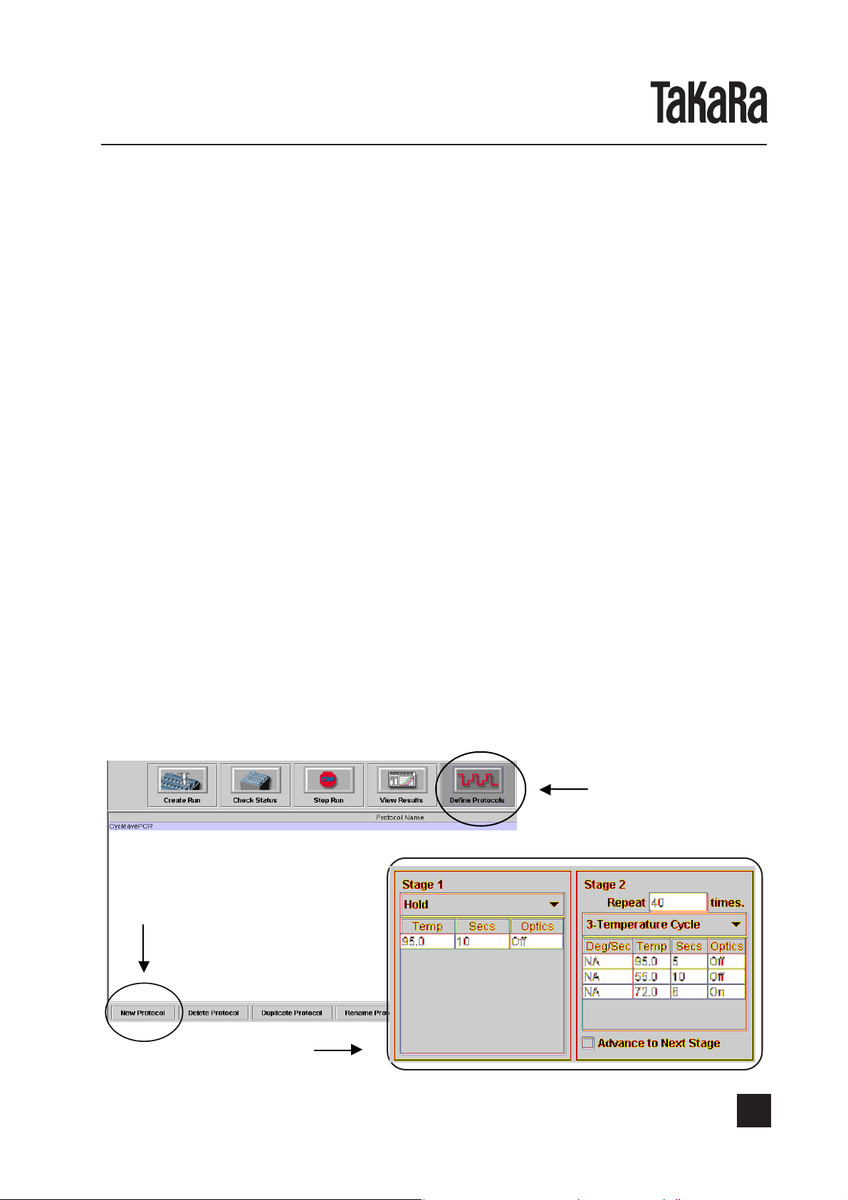
(1) Start the Smart Cycler® II System.
(2) Set the protocol.
Click the icon “Define Protocols” and then “New Protocol” button to create the protocol
by following the steps shown below. (Since the created protocol is saved, no entry is
required in subsequent reactions).
Crick New Protocol
Create this protocol
Define Protocols
URL:http://www.takara-bio.com
TAKARA BIO INC.
5
Page 6

CycleavePCRTM O157 (VT1/VT2) Detection Kit Ver.2.0
(3) Set the graphs. (Since the created graphs are saved, no entry is required in subsequent
reactions).
(3)-1. Set the amplification curve (FAM) for the amplified product derived from VT1.
Click the icon “Define Graphs” and create the graphs by following the steps shown
below.
(Since the graphs have been set under a name “FAM” at initialization, no entry is
required here).
(3)-2. Set the amplification curve (TET) for the amplified product derived from Internal.
Click the icon “Define Graphs” and create the graphs by following the steps shown
below.
(Since the graphs have been set under a name “TET” at initialization, no entry is
required here).
Cat.#CY203
v.0607
(3)-3. Set the amplification curve (ROX) for the amplified product derived from VT2.
below.
(Since the graphs have been set under a name “ROX” at initialization, no entry is
required here).
6
TAKARA BIO INC.
Click the icon “Define Graphs” and create the graphs by following the steps shown
URL:http://www.takara-bio.com
Page 7

CycleavePCRTM O157 (VT1/VT2) Detection Kit Ver.2.0
(4) Click the icon “Create Run”, enter Run Name, and select Dye-Set (FTTR25 in Smart
Cycler
Click the “Add/Remove Site” button and the “Select Protocols and Sites” screen appears.
From the menu, select the Site and Protocol to be used.
Enter Run Name
®
or FTTC25 in Smart Cycler® II ).
Select FTTC25 in
Dye Set.
Cat.#CY203
v.0607
VI-3. Preparation of reaction mixture:
This product detects simultaneously three amplification products, VT1, VT2, and internal
control, within one reaction tube. In order to obtain the right detection result, we recommend
you to perform VT1 positive control reaction, VT2 positive control reaction, and a negative
control reaction altogether.
(1) Prepare the reaction mixture on ice shown below. (Perform in Area 1)
Prepare the mixture except adding template in the tubes of required number plus a few.
Dispense it into Smart Cycler® tubes and then add template. The required number means
sample number plus three. This additional three means the tubes which are added with
VT1 positive control or VT2 positive control, or sterilized distilled water in place of template,
respectively.
Click the Add/Romove Sites to display
the [Select Protocol and Sites] screen.
Choose the site and protocol to
be used.
Click the [OK] button.
URL:http://www.takara-bio.com
TAKARA BIO INC.
7
Page 8

CycleavePCRTM O157 (VT1/VT2) Detection Kit Ver.2.0
Per reaction final conc.
5 X Reaction Mixture 5 µl 1 X
VT Primer Mix (5 µl each) 2 µl 0.4 µM each
VT Chimera Probe Mix (5 X conc.) 5 µl 1 X
TaKaRa Ex Taq R-PCR (5 units/µl) 0.25 µl 1.25 units
Tli RNase H II (200 units/µl) 0.5 µl 100 units
Sample DNA or Positive Control 1~10 µl
Sterilize distilled water up to 25 µl
Sample (template) solution is added in the volume range of 1-10 µl. Add sterilized distilled
water to have the final volume of 25 µl. In case of adding positive control, add 1 µl as
template.
Add the components of the above reaction mixture without template into a fresh tube, by
pouring on the tube wall. Please refer to the following figure.
Place the reaction mixture (15-24 µl)
into this reserver part.
Cat.#CY203
v.0607
Close gently the lid of the tubes not so tightly and move to the Area 3.
(2) Addition of sample template (Perfom in Area 3):
Prepare one tube of negative control by adding sterilized distilled water instead of sample.
For the rest tubes, add the prepared samples into the reaction mixture prepared at (1),
and close the lid of the tube tightly.
Centrifuge to load down the reaction
mixture into this part of the tube.
(3) Load the reaction tubes on Smart Cycler® II System and click the "Start Run" button to start
the reaction process.
8
TAKARA BIO INC.
URL:http://www.takara-bio.com
Page 9

CycleavePCRTM O157 (VT1/VT2) Detection Kit Ver.2.0
VI-4. Display of results:
(1) View the View Results screen. (The same time the reaction process is started, the View
Results screen automatically appears. If another screen is open, click the icon “View
Results”).
(2) Click the “Select Graphs” button and the Select Graphs screen appears. From the menu,
select FAM (VT1 amplified curve), TET (Internal control amplified curve) ROX (VT2
amplified curve), and Temperature (the temperature chart graph).
Click and show the "Select Graphs".
When the graphs for FAM, TET, ROX, and
Temperature have been selected at the
initial setting, no entry is required here.
Cat.#CY203
v.0607
Choose the site and
protocol to be used
and click the [OK] button.
(3) From the Views list, select “Results Table” and enter Sample ID.
Click the
"Results Table".
Enter sample ID.
(4) Click “Analysis Settings” for opening. Click “Usage” next to Ch#4 and select “Unused” from
the pull-down menu. In the Analysis Settings screen, set Manual Thresh Fluor. Units for
Ch#1, Ch#2 and Ch#3 to 100. After entering data in the cells, click the “Update Analysis”
button, and the settings are activated. This value is used as a cut-off value.
URL:http://www.takara-bio.com
TAKARA BIO INC.
9
Page 10

CycleavePCRTM O157 (VT1/VT2) Detection Kit Ver.2.0
(5) Select the amplified curve of interest in the above Views
Amplified curve for FAM
(VTI gene)
Cat.#CY203
v.0607
Amplified curve for TET
(Internal control)
Amplified curve for ROX
(VT2 gene)
10
TAKARA BIO INC.
URL:http://www.takara-bio.com
Page 11

CycleavePCRTM O157 (VT1/VT2) Detection Kit Ver.2.0
(6) After the reaction process terminates, click “Results Table” for viewing. Look at data in
the FAM Std/Res (Standard/Results) column for verifying the results. If the fluorescent
signal value for amplified product derived from the VT1 gene is 100 or larger, “POS” is
displayed in the cell of the " FAM Std/Res ". If it is smaller than 100, “NEG” is displayed.
Similarly, the results derived from VT2 gene appear in the " TxR Std/Res " column, and the
results derived from Internal Control appear in the " TET Std/Res ".
The result of internal control detection is displayed.
The result of VT1 gene detection is displayed.
Cat.#CY203
v.0607
VI-5. Judgement
If the fluorescent signal value for FAM detection is 100 or larger in the 50-cycle real time PCR
process, “POS” is displayed in the cell of the FAM Std/Res (the results of detection of the
fluorescent signal derived from VT1 gene) in the Results Table, while if it is smaller than
“100”, NEG is displayed.
If the fluorescent signal value for ROX detection is 100 or larger, "POS" is displayed in the cell
of ROX Std/Res ( the detection result of the fluorescent signal derived from VT2 gene) in the
Results Table, while NEG is displayed if it is smaller than 100.
TET Std/Res (the results of detection of the fluorescent signal derived from Internal Control)
are also displayed in the same manner as those for FAM. Based on the results, judgement
should be made with the reference table for judgement shown in page 15.
(NOTE) In some cases, “POS” may appear in the cell of the FAM Std/Res, TET Std/
Res, or ROX Std/Res column accidentally due to the signal noises other than
those from the amplified product. The shape of the amplified curve must be
checked to see if a sigmoid curve has been drawn allow to correct determina
→ See also the section “Trouble shooting” (in page 19).
The result of VT2 gene detection is displayed.
tion.
URL:http://www.takara-bio.com
TAKARA BIO INC.
11
Page 12

CycleavePCRTM O157 (VT1/VT2) Detection Kit Ver.2.0
Judgment flow chart
Judgment of VT1
○
Displayed on FAM Std/Res as
OOO in the system added with
the sample.
Displayed as POS Displayed as NEG
Cat.#CY203
v.0607
It was displayed on FAM Std/
Res as OOO in VT1 negative
control.
Displayed as POS Displayed as NEG
VT1 contamination is
suspected. Perform the
reaction again after
decontaminating the
place where the reaction
mixture is prepared, and
the apparatus to be used.
VT1 gene positive,
regardless of the result
of internal control (ROX
Std/Res) (whichever it is
POS or NEG).
Displayed on TET Std/Res as
OOO in the system added with
the sample.
Displayed as POS Displayed as NEG
It was displayed on FAM Std/
Res as OOO in VT1 positive
control.
Displayed as POS Displayed as NEG
There is no problem
about VT1 detection
system. VT1 gene in a
sample is below a detection limit.
There is a problem
about VT1 detection
system. A problem is in
primer for VT1 amplification, or in a detection
probe, or VT1 positive
control has decomposed.
Internal control is not
amplified, either. There is
a certain problem about
the whole reaction system, and reaction and
detection are not performed normally. Reform
the reaction again.
12
TAKARA BIO INC.
URL:http://www.takara-bio.com
Page 13

CycleavePCRTM O157 (VT1/VT2) Detection Kit Ver.2.0
Judgment of VT2
○
Displayed on TxR Std/Res as
OOO in the system added with
the sample.
Displayed as POS Displayed as NEG
Cat.#CY203
v.0607
It was displayed on TxR Std/
Res as OOO in VT2 negative
control.
Displayed as POS Displayed as NEG
VT2 contamination is
suspected. Perform the
reaction again after
decontaminating the
place where the reaction
mixture is prepared, and
the apparatus to be used.
VT2 gene positive,
regardless of the result
of internal control (TET
Std/Res) (whichever it is
POS or NEG).
Displayed on TET Std/Res as
OOO in the system added with
the sample.
Displayed as POS Displayed as NEG
It was displayed on TxR Std/
Res as OOO in VT2 positive
control.
Displayed as POS Displayed as NEG
There is no problem
about VT2 detection
system. VT2 gene in a
sample is below a detection limit.
There is a problem
about VT2 detection
system. A problem is in
primer for VT2 amplification, or in a detection
probe, or VT2 positive
control has decomposed.
Internal control is not
amplified, either. There is
a certain problem about
the whole reaction system, and reaction and
detection are not performed normally. Reform
the reaction again.
URL:http://www.takara-bio.com
TAKARA BIO INC.
13
Page 14

CycleavePCRTM O157 (VT1/VT2) Detection Kit Ver.2.0
Reference table for judgement:
Table 1: Reactions with a sample (Final judgement should be done by referring to
the results of each control reaction)
TET Std/Res (International control)
POS NEG
FAM POS VT1 Positive
Std/Res
(VT1) NEG VT1 Below the detection limit*2 Judgement impossible
TxR POS VT2 Positive
Std/Res
(VT2) NEG VT2 Below the detection limit*2 Judgement impossible
Table 2: VT1 positive control reactions (VT2 negative control)
TET Std/Res (International control)
POS NEG
FAM POS No problem in VT1 detection No problem in VT1 detection
Std/Res
(VT1) NEG Problem
*4
TxR POS VT2 contamination suspected*6 VT2 contamination suspected
Std/Res
(VT2) NEG No VT2 contamination*2 Judgement impossible
*1
VT1 Positive
*1
VT2 Positive
in VT1 detection Judgement impossible
Cat.#CY203
v.0607
*1
*3
*1
*3
*1
*3
*6
*3
Table 3: VT2 positive control reactions (VT1 negative control)
TET Std/Res (International control)
POS NEG
FAM POS VT1 contamination suspected*6 VT1 contamination suspected
Std/Res
(VT1) NEG No VT1 contamination
*2
Judgement impossible
*3
TxR POS No problem in VT2 detection No problem in VT2 detection
Std/Res
(VT2) NEG Problem*5 in VT2 detection Judgement impossible
*3
Table 4: Negative control (What added sterilization distilled water)
TET Std/Res (International control)
POS NEG
FAM POS VT1 contamination suspected*6 VT1 contamination suspected
Std/Res
(VT1) NEG No VT1 contamination
*2
Judgement impossible
*3
TxR POS VT2 contamination suspected*6 VT2 contamination suspected
Std/Res
(VT2) NEG No VT2 contamination
*2
Judgement impossible
*3
*6
*6
*6
14
TAKARA BIO INC.
URL:http://www.takara-bio.com
Page 15

CycleavePCRTM O157 (VT1/VT2) Detection Kit Ver.2.0
*1. The VT1 or VT2 gene is determined to be positive whether the result of Internal
Control is POS or NEG. Confirm that there is no contamination in the reaction referring to
the result of negative control reaction.
*2. Confirm that a positive control reaction is proved to be POS. That is, there is no
contamination in the reaction.
*3. The PCR reaction or cycling probe detection process was not be correctly performed for
some reason. Retry the reaction process. Substances that inhibit reaction can be included
in the sample. Repreparation of sample may be required.
*4. It is suspected that there may be problem in Primers for VT1 amplification or in Probe
for VT1 detection, or that VT1 Positive Control may be degraded.
*5. It is suspected that there may be problem in Primers for VT2 amplification or in Probe
for VT2 detection, or that VT2 Positive Control may be degraded.
*6. Contamination is suspected. Retry after decontamination of the place where the reaction
mixture is prepared and the equipment used.
VII. Trouble shooting
(1) A numeric value appears in the FAM,TET, or TxR Std/Res column instead of POS or NEG.
→ When Sample Type has been set as STD in Results Table, a numeric value
appears.
All the data in the Sample Type must be set as UNKN.
(2) POS appears in the FAM Std/Res ,TET Std/Res, or ROX Std/Res column accidentally
due to, for example, the signal noises other than those from the amplified product.
→ Make judgement based on the shape of the amplified curve. If the judgement is
difficult, retry the reaction process.
Cat.#CY203
v.0607
1111000000
1111000000
Amplified curve derived from
an amplified product
(Sigmoid curve is drawn.)
00
Increased signal due to any
other reason than an amplified
product
00
URL:http://www.takara-bio.com
TAKARA BIO INC.
15
Page 16

CycleavePCRTM O157 (VT1/VT2) Detection Kit Ver.2.0
(3) The background appears to be high, because the weak fluorescent signal has been
detected and the Y-axis scale on the graph has been automatically adjusted to the
value for the detected signal.
→ Adjust the Y-axis scale manually.*
1. Click any point near the Y-axis scale with
a right mouse button to open the Axes
Graph Scale screen.
2. Enter an appropriate value (for example, the
value along the Y-axis in the positive
control reaction) in the Max field in the YAxis (F1.) and click the “Apply” button.
3. Click the “Exit” button to close the Axes
Graph Scale screen.
* During reaction, no scale can be adjusted. Scale adjustment must be done after all
the reactions are terminated.
Cat.#CY203
v.0607
Y-axis value adjusted according to
fluorescent signal value
VIII. Reference:
After the Y-axis Max value was
manually adjusted to 500
1.Takao,T., T.Tanabe, Y.-M.Hong, Y.Shimonishi, H.Kurazono, T.Yutsudo, C.Sasakawa,
M.Yoshikawa and Y.Takeda:(1988). Identity of molecular structure of Shiga-like
toxin(VT1)from
2.Jackson,M.P., R.J.Neil, A.D.O’Brien, R.K.Holmes and J.W.Newland(1987). Nucleotide
sequence analysis and comparison of the structural gene for Shiga-like toxin Öü and
Shiga-like toxin II encoded by bacteriophages from
Microbio.Lett
3.Ito,H.,A.Terai,H.Kurokawa,Y.Takeda and M.Nishibuchi:(1990).Cloning and nucleotide
sequencing of Vero toxin 2 variant genes from
patient with the haemolytic uremic syndrome,
4.Weinstein,D.L.,M.P.Jackson,J.E.Samuel,R.K.Holmes and A.D. O’Brien: (1955). Cloning and
Sequencing of a Shiga-like toxin typeII variant from a
edema disease of swine,
Esherichia coli
., 44:109-114
O157: H7 with that of Shiga toxin,
Escherichia coli
Escherichia coli
Microb.Pathog
J.Bacteriol
., 170:4223-4230
Microb.Pathog
933,
O91:H21 isolated from a
.,8:47-60
Escherichia coli
., 5: 357-369
FEMS
strain responsible for
16
TAKARA BIO INC.
URL:http://www.takara-bio.com
Page 17

CycleavePCRTM O157 (VT1/VT2) Detection Kit Ver.2.0
Cat.#CY203
v.0607
IX. Related products:
CycleavePCR
CycleavePCR
CycleavePCR
TM
Bovine Sexing Kit (Cat.# CY201)
TM
Mycoplasma pneumoniae Detection Kit (Cat.# CY202)
TM
Salmonella
Detection Kit (Cat.# CY205)
NOTE: For research use only.
Not for use in human and animal diagnostic or therapeutic.
NOTICE TO PURCHASER: LIMITED LICENSE
A license under the foreign counterparts of U.S. Patents Nos. 4,683,202, 4,683,195 and 4,965,188 owned by
F.Hoffmann-La Roche Ltd. and U.S. Patent No. 5,075,216 and its foreign counterpart, owned by Roche Molecular
Systems, Inc. and F.Hoffmann-La Roche Ltd. for use in research and development, has an up-front fee component and
a running-royalty component. The purchase price of this product includes limited, nontransferable rights under the
running-royalty component to use only this amount of the product to practice the polymerase chain reaction (PCR) and
related processes described in said patents where such processes are covered by patents solely for the food and
environmental testing activities of the purchaser when this product is used in conjunction with a thermal cycler whose
use is covered by the up-front fee component. Rights to the up-front fee component must be obtained by the end user
in order to have a complete license to use this product in the PCR process where the process is covered by patents.
These rights under the up-front fee component may be purchased from Applied Biosystems or obtained by purchasing
an authorized thermal cycler. No right to perform or offer commercial services of any kind using PCR, where the process
is covered by patents, including without limitation reporting the results of purchaser's activities for a fee or other
commercial consideration, is hereby granted by implication or estoppel. Further information on purchasing licenses to
practice the PCR process where the process is covered by patents may be obtained by contacting the Director of
Licensing, Applied Biosystems, 850 Lincoln Centre Drive, Foster City, California 94404 or the Licensing Department,
Roche Molecular Systems, Inc., 1145 Atlantic Avenue, Alameda, California 94501.
Purchase of this product is accompanied by a limited licence to use it in the Polymerase Chain Reaction (PCR) process
for "Food and Environmental Testing" in conjunction with a thermal cycler whose use in the automated performance of
the PCR process is covered by the up-front licence fee, either by payment to Applied Biosystems or as purchased, i.e.,
an auhorized thermal cycler.
A portion of this product is subject to proprietary rights of Epoch Biosciences, Inc. and are made and sold under license
from Epoch Biosciences, Inc. under the patents and patent applications (US20020155484, WO0142505,
WO02099141, US10/113,445, US09/876,830 and corresponding patents issued in other countries).
There is no implied license for commercial use with respect to this product. A license must be obtained directly from
Epoch Biosciences, Inc. with respect to any proposed commercial use of this product, and “commercial use” includes
but is not limited to (A) the sale, lease, license or other transfer of this product or any material derived or produced from
it, (B) the sale, lease, license or other grant of rights to use this product or any material derived or produced from it, (C)
the use of this product to perform services for a fee for third parties (including contract research), and (D) the sale, lease,
license or other transfer of kits which include this product.
Sold under license from ID Biomedical.
*U.S. Patent 5,436,149 for LA Technology owned by TAKARA BIO INC.
Licensed under U.S. Patent 5,338,671 and 5,587,287 and corresponding patents in other countries.
URL:http://www.takara-bio.com
Phone: +81-77-543-7247 Fax: +81-77-543-9254
TAKARA BIO INC.
17
 Loading...