


T-K3
CONFIDENTI AL
T-K3 Service Manual
Ver. 1.05
T-K3 Instantaneous Water Heater
Service Manual
TAKAGI Ind ustrial Co. USA Inc.
5 Whatney
Irvine, CA 92618
Toll Free: (888) 882-5244 USA
Toll Free: (877) 877-4953 CANADA
1

CONFIDENTI AL
T-K3 Service Manual
Ver. 1.05
Table of Contents
1. Specifications of the T-K3, T-K3-OS, and T-K3-SP……………..………………………… 3
2. Exterior view ……………………...…….…………………………………………………….. 4
3. Interior view …………………………….…………………………………………………….. 5
4. List of main components in the interior view …….………………………………………… 6
5. Schematic diagram………………………………………………………………………….. 7
6. Wiring diagram………………………………………………………………………………. 8
7. Wiring diagram checkpoints f or diagnosis………………………..………………….….… 9
8. Resistance values of the temperature thermistors…………..…………………………… 10
9. Operational flow chart……………………………………………………………………… 11
Compo nent specifications………………...………………………………………………… 12
10.
Fault Analysis & Specifications……………………………………………………………... 32
11.
Controls and sett ings………………………………………………………………………… 40
12.
13. Compo nents diagrams……………………………………………………………….......... 65
14. Parts list……………………………………………………………………………………….. 68
15. Revisions……………………………………………………...…………………………….. 70
2
CONFIDENTI AL
T-K3 Service Manual
Ver. 1.05
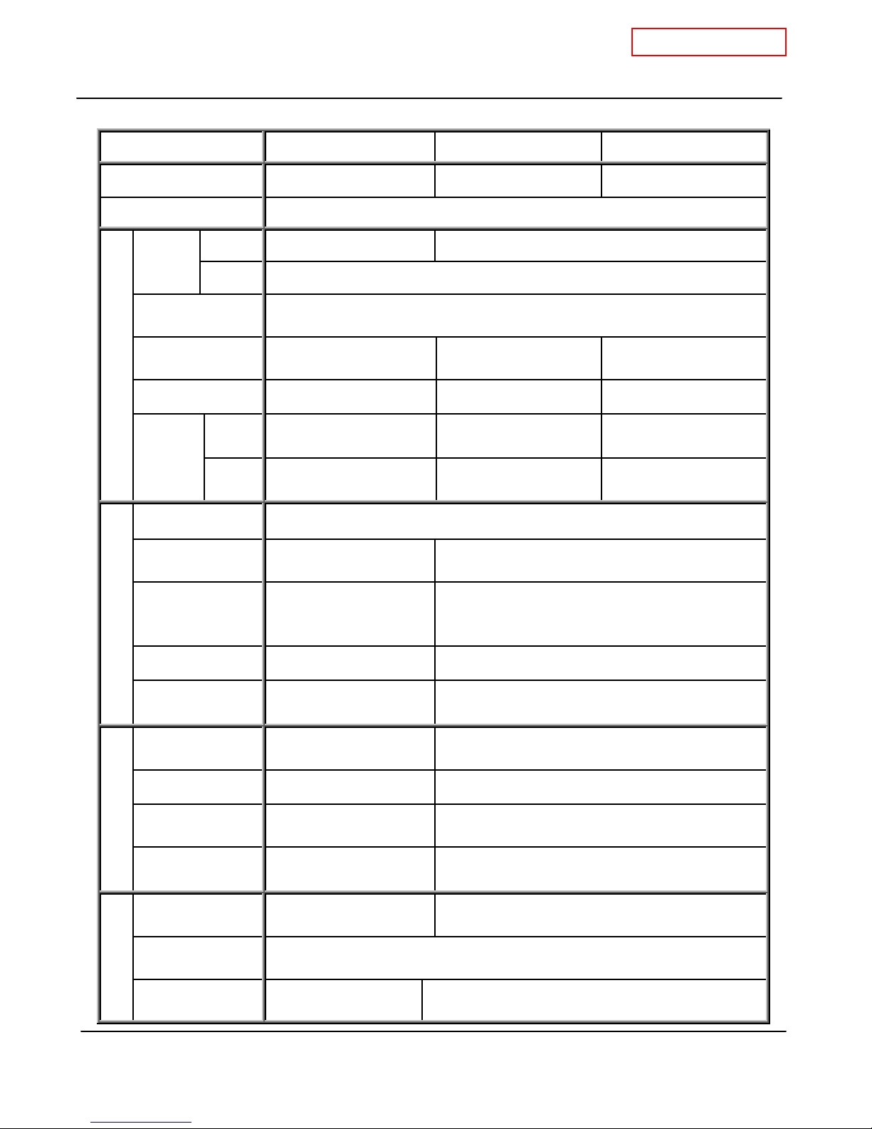
1. Specifications of the T-K3, T-K3-OS, and T-K3-SP
Mod el T-K3 T-K3-OS T-K3-SP
Dimensions H20.5"×W13.8"×D8.5" H20.5"×W13.8"×D8.5" H20.5"×W13.8"×D8.5"
Weight 40lbs.
INPUT
BTU/h
Combustion
Max 199,000 190,000
Min 11,000
Pow er vent
System
Ins ta lla tio n
Fan motor PWM turbo fan PWM fan PWM turbo fan
Combustion
Max
Man if old
Pressure
Min
Indo or, Outdoor,
& Direct-vent
LP 4.4” WC
Natural 2.5” W. C
LP 0.7” WC
Natural 0.4” W C
Outdoor Indo or & Outdoor
LP 3.1” WC
Natural 2.8” W. C
LP 0.8” WC
Natural 0.4” W C
LP 4.1” WC
Natural 2.4” W C
LP 0.8” WC
Natural 0.4” W C
Flow rate 0.5 GPM to 7.0 GPM
Available set
temp eratures
Temperature
dipsw itch settings
Water control
Bypass valve Yes N / A
99ºF ~ 185ºF
default: 122ºF
104ºF, 113ºF, 122ºF,
131ºF, 140ºF, 158ºF,
176ºF, 185ºF
99ºF ~ 167ºF
Default: 122ºF
113ºF, 122ºF, 140ºF, 167ºF
Thermisters
Remote controller
mod el
3 thermisters
(In,Out,Mixing)
TM-RE10
TM-RE30
2 thermisters (In,Out)
TK- RE02
PCB model T-K3 T-K3 OS/S P
Ind ic ator s
Operation
Pow er supply
control
Freeze protection
Self-combustion
“Burning” L ED &
7-SEG LED
GFI ( Including surge
absorber)
Cera mic heat ers and
Auto-firing system
Air-Fuel Ratio Det ection System
Surge absorber & Pow er switch
“Burning” L ED
Cera mic heat ers
improvement
Features
Easy-Link system Yes N / A
3
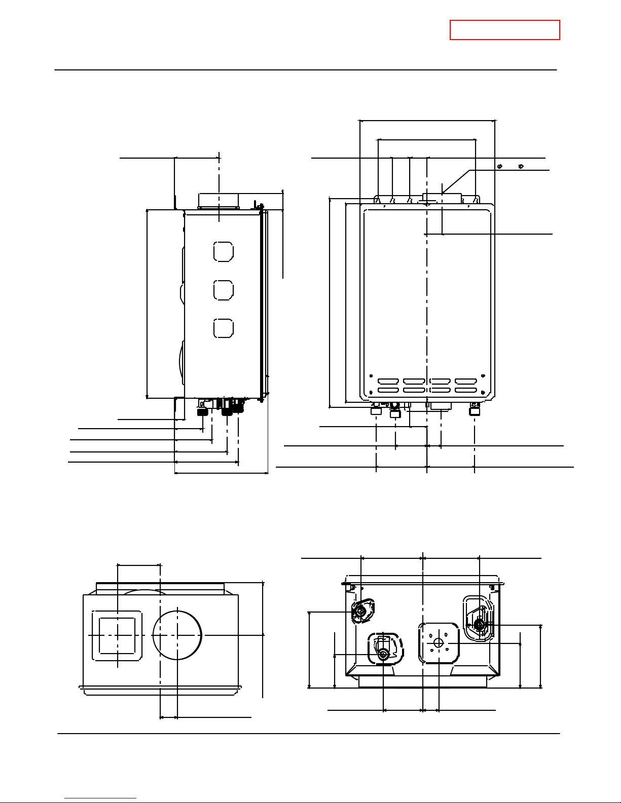
2. Exterior view
CONFIDENTI AL
T-K3 Service Manual
Ver. 1.05
4-1/2"(11 4.2mm)
Side view
Front view
13-3/4"(350mm)
10"(2 54mm)
1-3/4(45mm)1-3/4"(45m m)
4"( 101.6mm)
1-1/2"(37.8mm)
1-5/8"(42.5mm)
20-1/4"(520mm)
19-3/8"(492.7mm)
21-3/8"(544mm)
2-3/4"(72mm) COLD
3-3/4"(9 6.5mm) 120V
5-3/8"(1 36.1mm) GAS
6-1/2"(164.4mm) HO T
1"(26.3mm)
3-5/ 8"(93.3mm)
1-7/8"(47mm)
3-1/4"(8 4mm) COLD
9-1/2"(241.3mm)
5-1/4"(132.9mm) HOT
Top view Bottom view
5-1/4"(132.9mm) 4-7/ 8"(124 .3mm)
6-1/2 "(164.4mm)
2 -3/4"( 72mm)
4- 1/2"( 114.2m m)
1-1/ 2"(37.8mm)
3-1 /4"(84 mm)
1-3/8"(36mm)
1-3/8"(36mm) 120V
4-7/8"(124.3mm) GAS
5-3/ 8"(13 6.1mm)
3-3 /4"(96 .5mm)
4
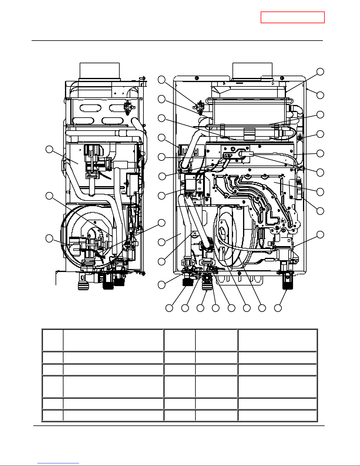
3. Interior view
CONFIDENTI AL
T-K3 Service Manual
Ver. 1.05
14
18
21
29
20
1
12
11
2
27
13
26
28
21
23
24
5
17
22
4
3
6
9
78
25
10
30
1516
19
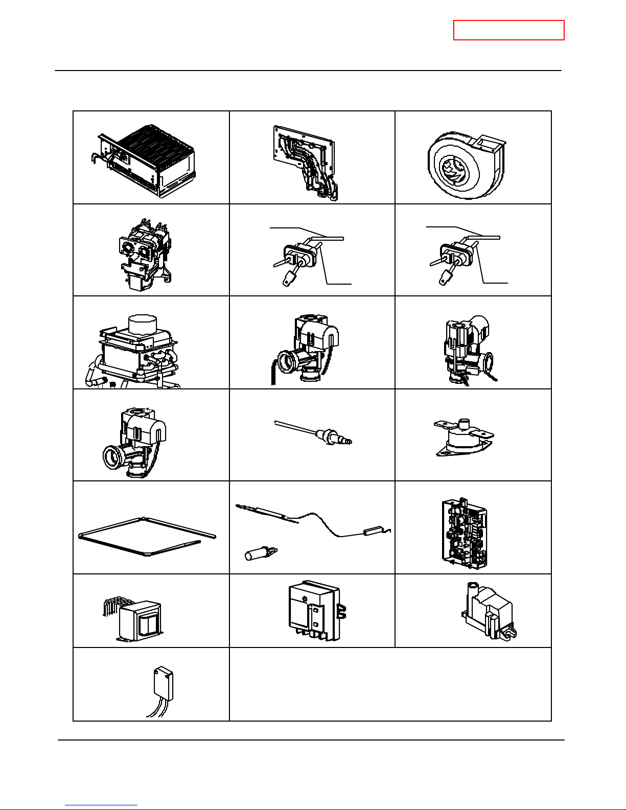
4. List of main components in the interior view
No. De s cr ipt ion
T- K 3
Pa r t#
1 Case assembly 001 EKK1D S P
2 Combustion cha mber 102 EKK1Y SP
Gas valve w ith Proportional
3
105 EKK1W OS, SP
valve
4 Compu ter board 701 EKK1L
5 Ign iter 704 EKN74 TKJr, TK1S, TH1, OS, SP
Ta k a g i
Par t #
Common parts
For other units
5
4. List of main components in the internal view (cont’d)
CONFIDENTI AL
T-K3 Service Manual
Ver. 1.05
No. De s cr ipt ion
T- K 3
Pa r t#
6 Transf ormer 702 EKH09 TH1, OS, SP
7 Water inlet 404 EKK1U OS, SP
8 Water outlet 405 EKK1V OS, SP
9 Mixing ther mistor 408 EKK1A
10 In let ther mistor 406 EKK38
11 Outlet ther mistor 407 EKK2 T
12 Overheat cut-off fuse 411 EKK0S
13 Burner assembly (Burners) 101 EKK1N OS, SP
14 Hi-limit sw itch 409 EKN34 TKJr, TK1S, TH1, OS, SP
15 Fan motor 104 EKK25 S P
16 Freeze protection ther mostat 705 EKJ59 TK2, TK1S, OS, SP
17 Flow sensor 402 EKK0T
18 Heat exchanger 401 EKK1X SP
Ta k a g i
Par t #
Common parts
with other models
19 Gas inlet 108 EKK1E OS, SP
20 Exhaust 401 EKK1X
21 Heater 412 EKK2R OS, SP
22 Flow adjustment valve 402 EKK0T
23 GFI 703 EKN73 TK1S, TKJr, TH1
24 Man ifold 103
25 Outlet drain plug 419 EKK2E OS, SP
26 Air-fuel ratio rod (AFR rod) 716 EKK0E OS, S P
27 Flame rod 716 EKK0E OS, SP
28 Ign iter rod 107 EKK0F OS, SP
29 Bypass valve 403 EKK0 U
30 In let drain plug 416 EKK2B OS, SP
EKK1T(NA)
OS, SP
EKK1S(LP)
6

5. Schematic diagram
Hi-limit SW
Outlet
Thermistor
CONFIDENTI AL
T-K3 Service Manual
Ver. 1.05
O.H.C.F
Air-fuel ratio rod
Flame rod
Bypass valve
Fan motor
Flow adjustment valve
w/ Flow sensor
Heater
Mixing
Thermi stor
Drain plug
Inlet
Thermistor
H
O
T
Inlet drain
plug f ilter
Ignite r rod
Igniter
Gas solenoid valve 3
PCB
G
A
C
O
L
D
Transformer
S
Gas proportional valve
Gas solnoid valve 1
Gas solenoid valve 2
Main gas valve
1. When a hot w ater tap is opened, cold w ater enters the T-K3 w ater heater.
The w ater flow sensor detects this w ater flow and sends this information to co mputer.
2.
The computer initiates fan motor and sends signal to igniter to create ignition spark.
3.
The main, proportional, and solenoid gas valves open to allow gas input.
4.
The gas ignites and f lames appe ar inside the burner chamber.
5.
Water circulates through the heat exchanger and is heated up to the set te mperature.
6.
Using ther mistors to measure temperatures, the computer modulates the gas and w ater
7.
valves to ensure proper output w ater temperatures.
When the tap is closed, the T-K3 w ater heater shuts dow n.
8.
7
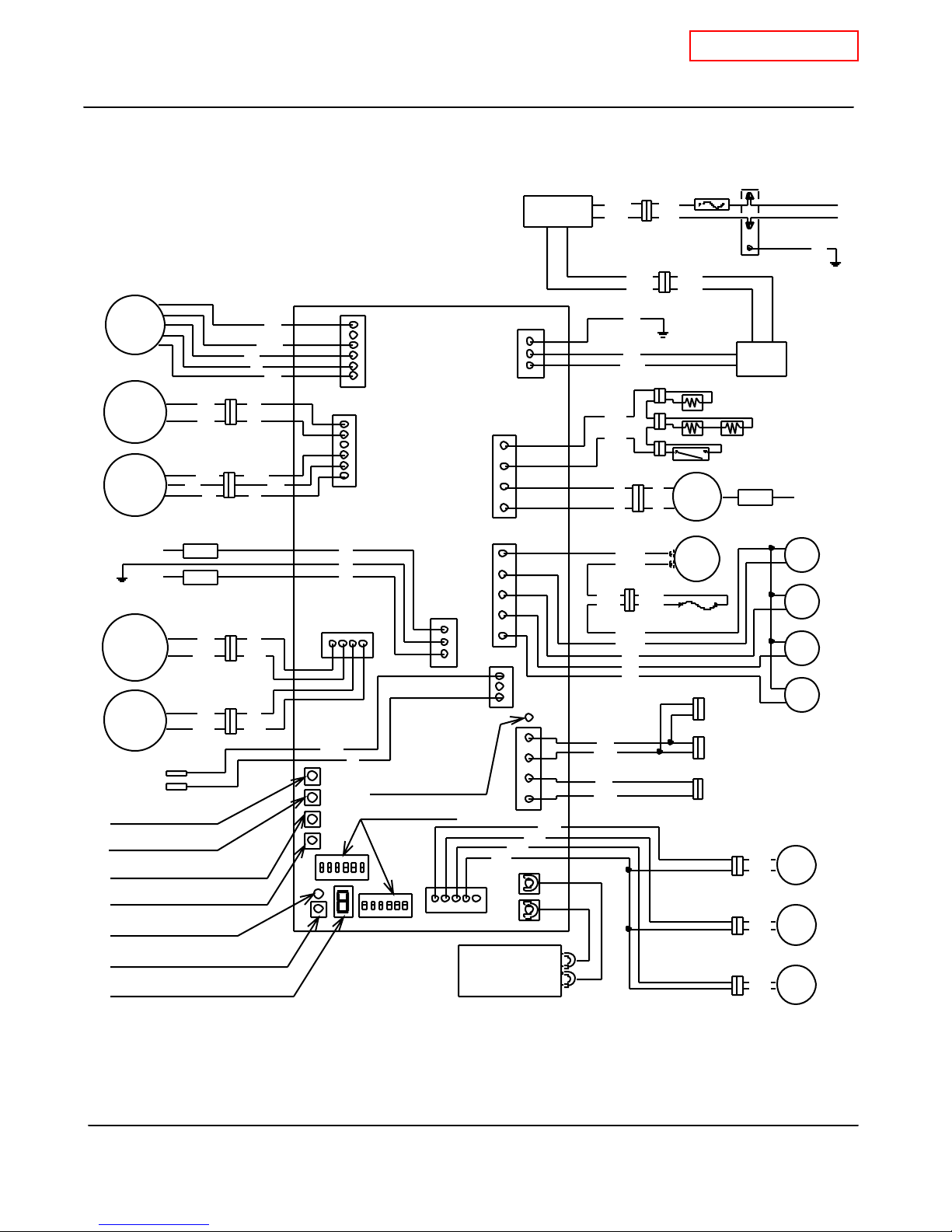
6. Wiring diagram
CONFIDENTI AL
T-K3 Service Manual
Ver. 1.05
W W hite
R R ed
BK Black
P P urple
LB Lig ht blue
F
M
Proportional
Valve
Flow
Senso r
Groun d
Flow
Adjust
ment
Valve
Bypass
Valve
Pump
MAX button
MIN button
Increase bu tton
Decrease bu tton
Burning lam p
Error call button
7 Seg LED
W
R
K
B
W
R
AFR r od
Flame r od
R
B
K
R
B
K
K
BK
BK
A2
K
B
W
A1
R
B
B
R
G
W
BK
BL Blue
G G reen
Y Y ellow
O O range
BR Brown
R
B
L
Y
O
W
W
R
G
H1
33
Transformer
A
B1
B
K
W
R
R
J1
K
B
R
J2
K
B
OFF
Y
G
O
BK
W
123456
H2
I
Multi-system
On line lamp
Dip switch
654321
OFF
7
B2
7
3
9
C
53
73
D1
D2
BK
Remote
Contro ller
BK
BK
BK
F
C2
C1
BL
BL BL
W
BK
W
BK
P
P
P
P
BL
BL
BL
BL
LB
G
O
R
3A
B
K
W
B
R
B
R
Ground
Heater
Freez e
prote ction
therm ostat
IG
Hilimit
switch
O.H.C. F
SLAVE IN
SLAVE OUT
MASTER
Mixin g
therm istor
E1
Outlet
thermi stor
E2
Inlet
therm istor
E3
AC120V
Ground
G
GFI
Heate r
Elect rod
MV
SV1
SV2
SV3
BK
BK
BK
8

7. Wiring diagram check points for diagnosis
CONFIDENTI AL
T-K3 Service Manual
Ver. 1.05
Check-
Part and Description Color of wires Normal range
point
Brown – Brown (A1)
A, A1 100V Power supply
AC 90~11 0 V
White – Black (A)
A2 120V Power supply Black - White AC 108~132V
B1 Heater Black - Black AC 90~11 0 V
B2 Ig niter Purple - Pu rpl e AC 9 0~11 0 V
Light blue - blue at COM
Green - blue at COM
DC 78~100V(in operation) / 0.9~1.3kΩ
DC 78~100V(in operation) / 1.3~1.9kΩ
C Gas val ves
Orange - blue at COM
Red - blue at COM
C Proportional Valve White - red at COM
DC 78~100V(in operation) / 1.3~1.9kΩ
DC 78~100V(in operation) / 0.9~1.7kΩ
DC 1~10V(in operation) / 30~51Ω
C1 Hi-limit switch Blue - Blue Less than DC 1V and less than 1.3Ω
C2 Overheat cutoff fuse Blue - Blue Less than DC 1V and less than 1.3Ω
D1 Black - White DC 15V (during Easy-Link operation)
Easy link connectors
D2
Black - White DC 15V
E1 Mixing thermistor Black - Black
E2 Outlet thermistor Black - Black
See table on p. 10
E3 Inlet thermistor Black - Black
F Remote controller * DC 11~25V
Red - Blue DC 110 ~160V
G Fan motor
Yellow - Blue DC 13~17V
Orange - Blue DC 2~6.5V
White - Blue See the “A
H1 Gas proportional valve White - red DC 1~10V and 30~50Ω
Red - Black DC 4~5.5V
H2 Flow sensor
Whi te - Bla ck DC 1~4V (1080pulse / min)
Air-fuel ratio flame rod Yellow - AFR rod More than 1μA (during burning)
I
Flame rod Orange - Flame rod More than 1μA (during burning)
J1 Flow adjustment valve Red - Black DC 7~16V and 0.09~0.2kΩ
J2 Bypass valve Red - Black DC 7~16V and 0.09~0.2kΩ
K Pump connector port White - Black Less than 1.3Ω
9
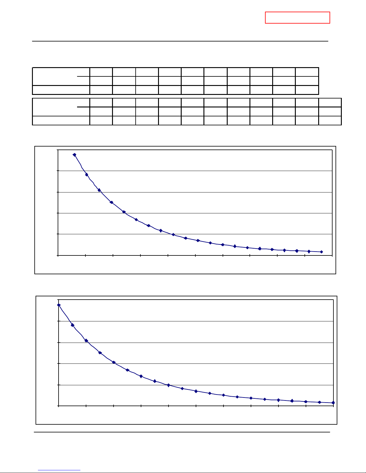
8. Resistance values of the temperature thermistors
Resis tance values at different temperatures
CONFIDENTI AL
T-K3 Service Manual
Ver. 1.05
Temperature
ºF 32 41 50 59 68 77 86 95 104 113
ºC 0 5 10 15 20 25 30 35 40 45
Resistance kΩ 23.76 19.08 15.43 12.56 10.28 8.47 7.02 5.85 4.90 4.12
Temperature ºF 122 131 140 149 158 167 176 185 194 203 212
ºC 50 55 60 65 70 75 80 85 90 95 100
Resistance kΩ 3.49 2.96 2.53 2.16 1.86 1.60 1.39 1.21 1.05 0.92 0.81
Temperature(ºF) vs. Resistance(kΩ)
25.00
20.00
15.00
10.00
Resisitance (kΩ)
5.00
0.00
20 40 60 80 100 120 140 1 60 180 200 220
Temperature(
25.00
20.00
15.00
10.00
Resisitance (kΩ)
5.00
0.00
0 102030405060708090100
℃)
vs. Resistance(kΩ )
Temperature (ºF)
Temperature (ºC)
10
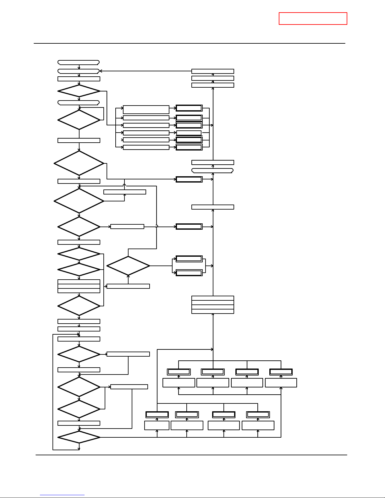
9. Operational flow chart
Power supply ON
Opeartion SW ON
OPEN FAV BV
YES
YES
NO
Miss select
NO
gas type
InTH failure
OuTH failure 311 blink
MiTH failure 331 blink
PCB failure
SV circuit failure
Pre-check
NORMAL?
OPEN the tap
Flow Sensor
Above 0.5GPM?
BV action
Remove cause
Opeartion lamp OFF
OPEARTION OFF
031 blink
321 blink
701 blink
511 blink
CONFIDENTI AL
T-K3 Service Manual
FAV ; Flow Adjustment Valve
B V ; Bypass Valve
F M ; Fan Motor
OHCF; Over Heat Cut-off Fuse
M V ; Main gas Valve
SV1 ; Solenoid Valve 1
SV2 ; Solenoid Valve 2
SV3 ; Solenoid Valve 3
GPV ; Gas Proportional Valve
InTH; Inlet thermistor
OuTH; Outlet thermistor
MiTH; Mixing thermistor
PCB ; Print Circuit board
(Computer board)
AFR ; Air Fuel Ratio
Ver. 1.05
YES
YES
A?
YES
YES
YES
YES
NO
NO
NO
NO
NO
NO
(5sec later)
FM speed
(Below
1,000rpm?)
Start FM
FM speed
(Above
1,000rpm?)
Pseudo-flame
Below
ƒÊ
DC0.15
Iginiter ON
Hi-limit
Normal?
OHCF
Normal?
MV ON
SV1 ON
GPV ON
Detect Flame
Above
DC1.0uA?
Burning lamp ON
Iginiter OFF
Proportional control
(3sec later)
Stop FM
(20sec later)
Retry ignite
Success?
Igniter OFF
YES
Flow sensor OFF
CLOSE the tap
611 blink
STOP FM
721 blinkPeseudo-flame
NO
111 blink
121 blink
SV1, SV2, SV3 OFF
MV OFF
SV1 OFF
GPV OFF
YES
YES
YES
NO
NO
NO
NO
YES
SV2 SV3 OFF
FAV close
Change over
point?
SV2 SV3 ON
Above water
heat capability?
Above
Max flow rate
ristriction?
FAV OPEN
Safety devise
work?
OuTH OPEN
or SH ORT
AFR rod failure
32 1 blink
‡F
InT H OPEN
or SHORT
(20sec later)
11
Abnorm al
AFR
331 blink
MiTH OPE N
or SHORT
Melt OHCF
Above 363
‹
F
6 11 blink311 blink
A bnormal
F M Speed
121 blink121 blin k991 blink391 blink
Flame rod
failure
10. Component specifications
CONFIDENTI AL
T-K3 Service Manual
Ver. 1.05
1. Burners
4. G a s va l ve a sse m b l y
7. Heat exchanger
10. Bypass valve
P.13
P.16
P.19
2. Manifold
5. Flame rod
Flame rod
AFR Rod
8. Flow adjustment valve
11. Thermistors
P.14
P.17
P.20
3. Fan motor
P.15
6. AFR rod
Flame rod
AFR Rod
P.18
9. Flow sensor
P.21
12. Hi-limit switch
P.22
13. Overheat cutoff fuse
P.25
16. Transformer
P.28
19. Freeze protection
thermostat
P.31
14. Heaters
17. GFI
P.23
P.26
P.29
P.24
15. Computer board
P.27
18. Igniter
P.30
12
CONFIDENTI AL
T-K3 Service Manual
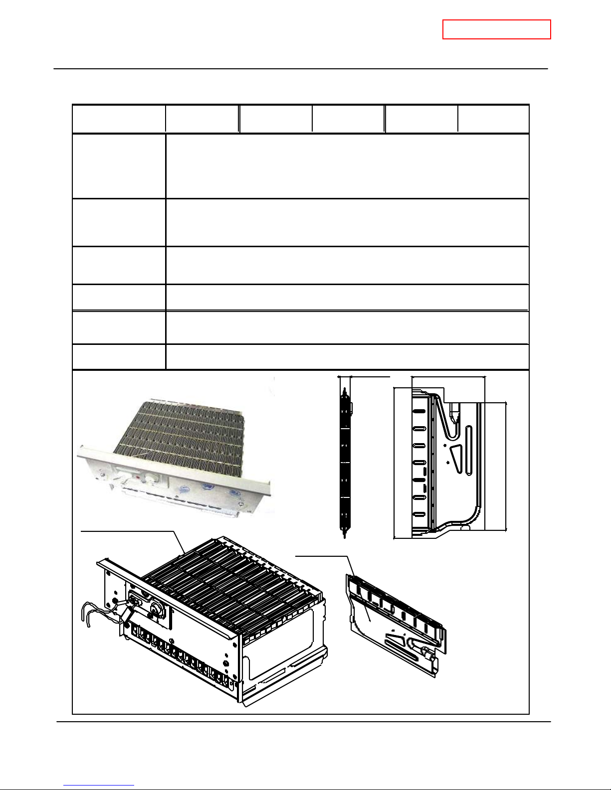
10-1 . Burners
T-K3 Part # #101 Takagi Part # EKK1N C heckpoint N/A
There are 2 types of burners in the T-K3: th e gas-r ich burner stabilizes the flames
Function
F ailure even t s
within the combustion chamber and the air-rich burner produces more heat in the
combustion chamb er. The burner s facilitate the air/g as mixture necessa ry to
pr oduce th e p ro pe r he at durin g the com bu stion react ion .
1. Unable to initialize/sustain combustion
2. Dust or soot deposit on the burner surface.
3. Cracks on the burners. 4. Gas leakage from burners
Ver. 1.05
Effects on the T-K3
if burners fails
Error codes when the
burners fail
D iag nostic
Color/Number of
wires
Sixt ee n T- K3 B urne rs
1. An un expect ed co mbus tion.
2. Unsta bl e f lam e condition s an d/ o r flam e loss.
3. Ignition failure.
111 121
Visual inspection: excessive dust deposit on the burner surface and/or unstable
flam e cond itions du ring o pe rat io n.
N/A
6-3/4" (170mm)
3-1/8" (80mm)
5-5/8" (143.2mm)
3/8" (11.0mm)
T-K3 B urne r
13
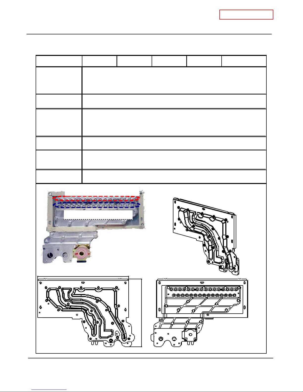
10-2. Gas manifold
CONFIDENTI AL
T-K3 Service Manual
Ver. 1.05
T-K3 Part # #103 Takagi Part # EKK1F Checkpoint
1. The manifold distributes gas from the gas valves to the burners. The manifold
Function
has t wo t ypes of the nozzles: one type f o r ga s-rich burners (16 noz zles) a nd th e
other f or air -ri ch burners (15 nozzles)
2. There are 3 zones within the manifold, to ensure efficient combustion operation.
Failure events
1. Dust deposit on the manifold. 2. Gas leakage from a failed manifold.
3. Ignition failure. 4. Imperfect combustion.
1. The burner s cannot re ceive proper gas flow from t h e ma nif o ld, which can ca use
Effects on the T-K3
if the manifold fails.
poor combustion in the combustion ch amber. In this case, the AFR rod will detect
an improper flame condition and computer will take safety measures.
2. Gas le akage fr om th e ma nifo ld.
Error codes when
the manifold fails.
111 121
1. Visual inspection: Excessive dust deposit around the nozzles or cracks on the
D iag no stic
manifold.
2. Check voltages and resistance: proper range of values shown below.
Color/Number of
wires
Blue -Red DC 78~100V / 0.9~1.7kΩ
Nozzles for gas-rich burners
N/A
Nozzles for air-rich burners
9-1/ 8" (23 2mm)
6-7/8" (175mm)
14
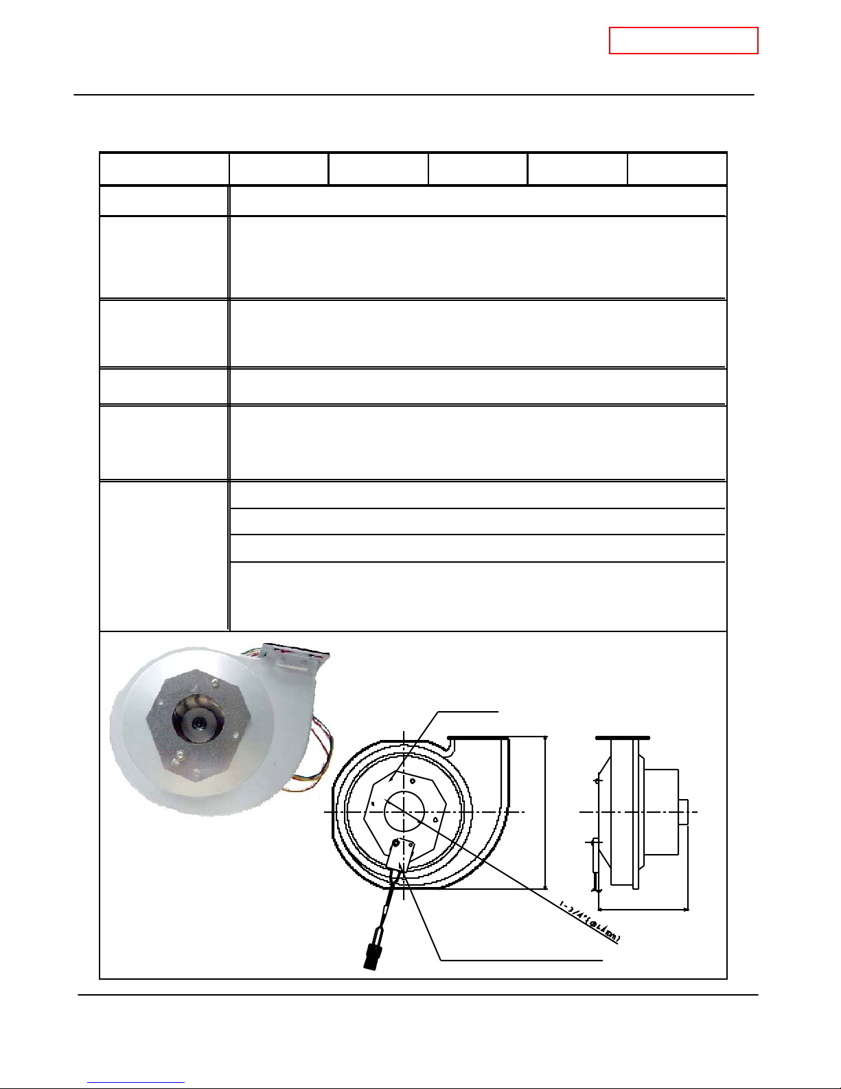
10-3. Fan motor
CONFIDENTI AL
T-K3 Service Manual
Ver. 1.05
T-K3 Part # #1 04 Takagi Part # EKK25 C heckpo int
Function
To pro vid e combustion air into t h e bu rn er chamber a nd t o exhau st flue gas.
1. Fan sp ee d f ail ure, causing ab no rmal so un ds wit h o r without combust io n in th e
F ailure even t s
operation.
2. Unexpected working caused by the connectors of the fan motor getting wet.
3. Drops out from the bottom of the combustion chamber
Effects on the T-K3
if fan motor fails
Error codes when
the fan motor fails.
1. T-K3 does not function properly
2. Failure to ignite or abnormal ignition
3. Unstable combustion conditions
611
1. Visual inspection: connection/breakage of wires or dust (causing electrical
D iag nostic
sh orta ge )
2. Voltage check: proper range of voltages shown below.
DC 110~160V (Input)
D C 13 ~1 7V (Input)
DC 2.0~6.5V (Input)
Color/Number of
Red- Blue
Yellow-Blue
Orange-Blue
wires
Verify the fan motor speed using the Diagnostics Mode of the
White-Blue
TM-RE10 temperature remote controller. See Section 12-1 for
details.
G
Fan da mper
A
S
A
H
I
Freez e protection thermo stat
6-1/2" (165.5mm)
3-3/ 4"(95.75mm)
15

10-4. Gas valve assembly
)
CONFIDENTI AL
T-K3 Service Manual
Ver. 1.05
T-K3 Part # #105 Tak agi Part # EKK1W Checkpoint
Opens and closes the gas pathways of the T-K3 (main and solenoid gas valves)
Function
Modulates the gas flow from the gas inlet (proportional gas valve)
1. Gas leak from the valves.
F ailure even t s
2. Unable to open/clo se (mai n an d solenoid gas valves)
3. Unable to modulate the gas flow (proportional gas valve)
1. Gas leak from the unit.
Effects on the T-K3
if valves fails.
2. Excess carbon monoxide emissions.
3. Lack of wate r t em pe ra t ure control .
4. No flames
Error codes when
the valves fail.
111 121 510 701 711
1. Visual inspection: connection/breakage of wires.
D iag nostic
2. Listen for "clunk" sounds from the gas valves opening right after fan motor
initi ates.
3. Check vo ltage s and resistance of c oils; proper r an ge of values shown below.
Color/Number of
wires
Blue -Red
Blue -light blue
Blue -Orange
Blue -Green
DC 78~100V / 0.9~1.7K
DC 78~100V / 0.9~1.3KΩ
DC 78~100V / 1.3~1.9K
DC 78~100V / 1.3~1.9K
Ω
Ω
Ω
C,H1
White - Red (Proportional Valve
Proportional Valve
Main g as val ve
2-5/8" (67mm)
1-3 /8 " (34mm)
D C 1~ 15 V / 20~40Ω
Solenoid valve
3-5/ 8" (91 .5mm)
4-1/4" (10 8mm) 7/8" (22.2mm)
Gas
valve
Proportional valve
4-5/8" (119 mm)
16
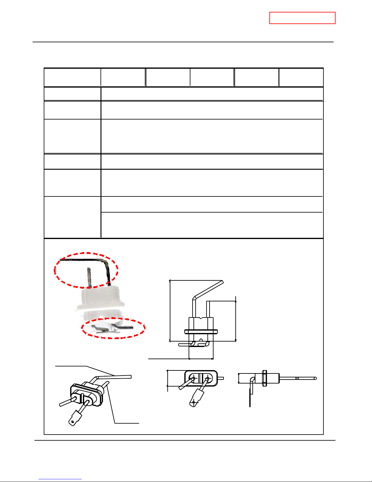
10-5. Flame rod
CONFIDENTI AL
T-K3 Service Manual
Ver. 1.05
T-K3 Part # #716 Takagi Part # EKK0E Checkpoint
Function
Failure event
Effects on the T-K3
if flame rod fails
Error codes when
the flame rod fails.
D iag nostic
Color/Number of
wires
To detect fla me s whil e unit i s in oper ation.
1 Unable to detect flames when flames actually do occur
2. Detecting a false f lam e wh en n o f la mes act ua lly occu r
1. The T-K3 stops operating. The "111" and/or "121" error code(s) will display
2. The T-K3 wi ll not initiate the ignitio n proc ess. T he "721" error code will display
111 121 721
1. Visual inspection: connection/breakage of wires or soot buildup on rod.
2. Check amperes: proper range of values shown below.
Orange(17) - Green(18)
Orange(17) - Flam e r od
between the f la me r od an d the
(during combustion) 40KHz~60KHz
(during combustion) 1μA or more
co mput e r bo ar d
The flame rod is assembled with the AFR rod.
I
Flame r od
Detecting elements (flame a nd AFR
Leads to computer board
AFR Ro d
3-1/2" (88.6mm)
1-3/8" ( 35mm)
7/8" (24mm)
2-1/4" (58.6mm)
5/8" (15mm)
17
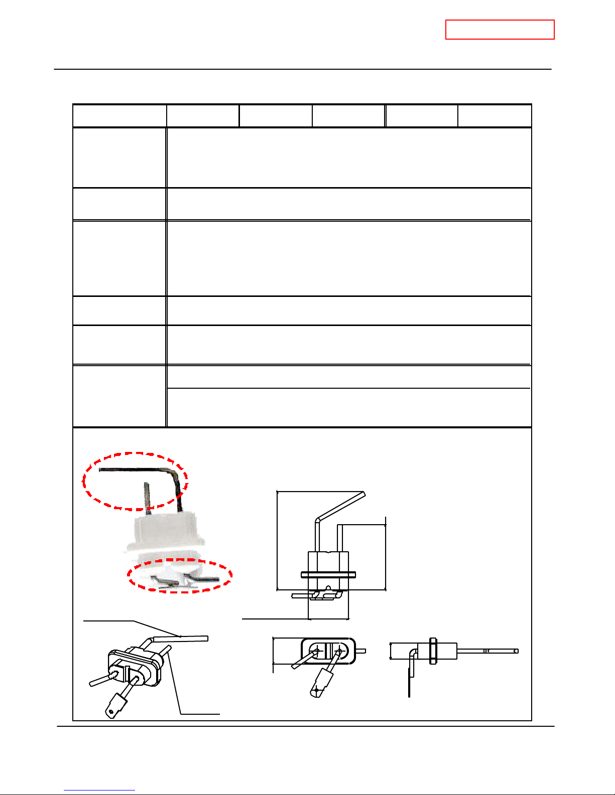
10-6 . AFR rod
CONFIDENTI AL
T-K3 Service Manual
Ver. 1.05
T-K3 Part # #716 Ta kagi Part # EKK0E Checkpoint
-Checks flame conditions during combustion.
Functions
- Wh en AFR rod detects un exp ected flam e con ditio ns, the T-K3's computer mak es
adjustments in the fan motor speed to compensate.
Failure event
1. Unable to detect flames when flames actually do occur
2. Detecting a false fl am e when no flames actua lly occu r
1. The T- K3 stops oper ating. The "111 " a nd /or "1 21" er ro r code(s) will disp lay
Effects on the T-K3
if the AFR rod fails
2. The T-K3 will not initiate the ignition process. The "721" error code will display
3. The fan motor spe ed can not be mo du lat ed pro perly under abnorma l f lam e
conditions, which can result in excessive CO em ission.
Error codes when
the AFR rod fails.
D iag no stic
Color/Number of
wires
101 991 391
1. Visual inspection: connection/braking of wires, soot on it.
2. Check voltages: proper range of values are shown below.
Yellow (8) - Green (18)
Yellow (8) - AFR rod:
between the A FR rod and the
(during operation) 40KHz~60KHz
(during operation) 1μA or more
co mput er boa rd
I
The AFR rod is assembled with the flame rod.
Detecting elements (AFR and flame rods)
3-1/2" (88.6mm)
Leads to computer board
Flame rod
AFR Rod
1-3/8" (35mm )
7/8" (24mm)
2-1/4" (58.6mm)
5/8" (15mm)
18

CONFIDENTI AL
T-K3 Service Manual
10-7. Heat exchanger
T-K3 Part # #401 Takagi Part # EKK1X Checkpoint N/A
Ver. 1.05
Function
Failure event
Effects on the T -K3
i f the heat
exchanger fails .
Error codes when the
heat exchanger fails.
D iag nostic
Color/Number of wires
Absorb heat from combustion and transfer it to water through the heat
exchanger pipes.
1. Clogged heat exchanger fins and/or cracks on the heat exchanger walls.
2. Leaking exhaust gas.
3. Improper heat transfer can cause the water in heat exchanger to boil.
1. Water leakage from the heat exchanger
2. Exhaust gas leakage (if this occurs, an overheat cutoff fuse is in place to
detect this event and immediately stop the T-K3 from operating)
3. Abnormal sounds during combustion
N/A
1. Visua l inspe ction: soot de po sits, cr ac k s o n t he heat exchanger walls , and/o r
water leakage from the heat exchanger.
2. In t he eve nt of abnormal so un ds during combustion :
A. Inspect for soot buildup inside the heat exchanger.
B . Ins pe ct fo r scale bu ildup i nside the he at exchanger pipes. Scal e bu ildup
obstructs proper heat transfer to the water, thereby overheating the heat
exchanger and causing damage.
N/A
Exhaust chamber
Heat exchanger
Water pipes
14-1/4" (361.3mm)
20-5/8" (522.5mm)
11-3/4" (297.2mm)
19
CONFIDENTI AL
T-K3 Service Manual
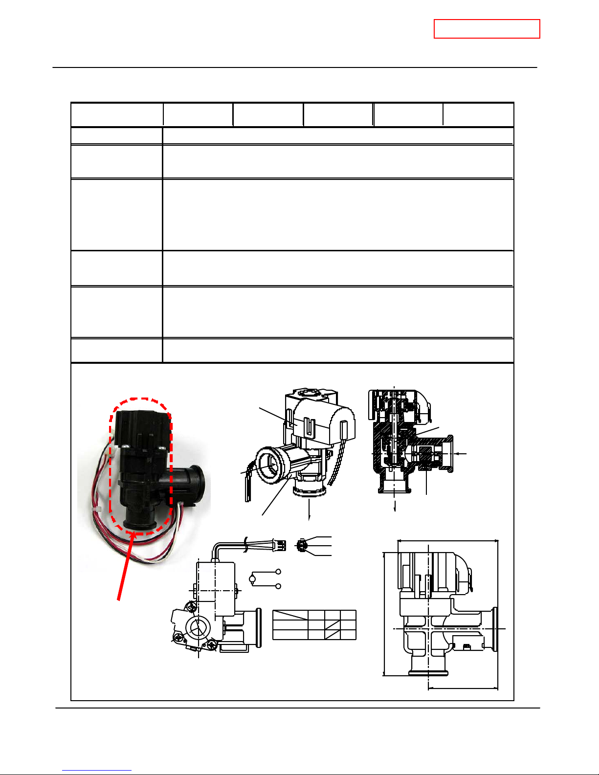
10-8. Flow adjustment valve
T-K3 Part # #402 Tak agi Part # EKK0T Checkpoint J1
Ver. 1.05
Function
F ailure even t
Effects on the T-K3
if flow adjustment
valve
fails
Controls water flow to properly control the output hot water temperaturet.
1. Water leakage from valve.
2. The valve cannot modulate or make open/close positions.
1. Wate r leaka ge from f a iled v al ve can da ma ge other T-K 3 co mp on en ts.
2. Temp er atur e fluctu atio ns in the hot wat e r ou tput.
3. Within a multi-unit Easy-Link system, the "651" error code can occur.
Error codes when
F low Adjust me nt
651 (only within multi-unit Easy-Link systems)
Va lve fail s.
1. Visual inspection: connection/breakage of wires, motor drive locked due to
D iag nostic
scal e bu ildup, a nd/ or water leak age.
2. Check vo ltage s and resistance ; prop er ran g e of val ues sh ow n below .
Color/Number of
wires
Black-Red
DC7~1 6V and 0.09~ 0 .2kΩ
The flow adjustment valve is assembled with the flow sensor.
Flow
adjustment
valve
Flow
adjustment
valve
Flow adjustment
val ve
IN
Flow sensor
Flow
adju stment
valv e
IN
Flow sensor
OUT
No.
3
No. 2
No.
1
(Bl ack)
1
M
(Re d)
3
Close
Open
132
-+
+ -
OUT
2- 5/8" (6 7.5mm )
>PPE-GF<
3-3/8" (84.4mm)
1-7/8" (47mm)
20
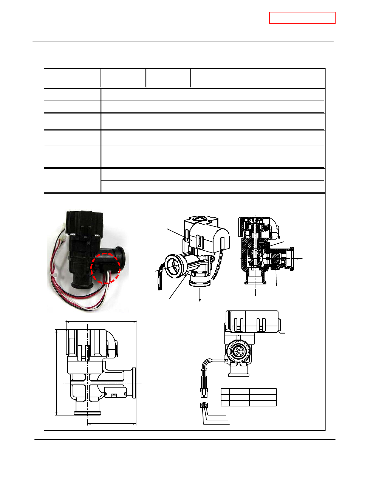
10-9 . Flow se nsor
u
CONFIDENTI AL
T-K3 Service Manual
Ver. 1.05
T-K3 Part # #402 Takagi Part # EKK0T Checkpoint
Function
Failure event
Effects on the T-K3
if flow sensor fails
Error codes when
the flow sensor fails.
D iag nostic
Color/Number of
wires
Detects and measures water flow rate using a spinning impeller and magnetic pick-
Unable to detect or measure any water flow rate.
Ignition sequence does not start (T-K3 will not initiate any operation)
441 (only within multi-unit Easy-Link systems)
1. Visual inspection: connection/breakage of wires and/or debris on impeller
2. Check voltages: proper range of values shown below.
Red-Black
W hite( 85) -Bla ck
DC 4~5.5V (Input)
DC 1~4 V (p ulse) 1,080 pu lse/m in (m ore tha n 1 8Hz)
The flow sensor is asse mbled with the flow adjus tment valve.
Flow
adjustm ent
valve
Flow sensor
H2
Flow
adjus tment
valve
2-5/8" (67.5mm)
3-3/8" (84.4mm)
>PPE-GF<
1-7/8" (47mm)
IN
Flow sen sor
OUT
Flow sensor
11
22
33
No.1
No.2
No.3
Red
White
Black
IN
Flow s ensor
OUT
VCC
OUTPUT
GND
21
 Loading...