

Page 1

M850-00
1
T850 Series II
Base Station Equipment
400-520MHz
Service Manual
Issue 200
October 1998
M850-00-200
Copyright TEL 31/09/98
Page 2

2
M850-00
T800
T800
Head Office
New Zealand
Tait Electronics Ltd
558 Wairakei Road
P.O. Box 1645
Christchurch
New Zealand
Phone: 64 3 358-3399
Fax: 64 3 358-3903
Radio Systems Division
535 Wairakei Road
P.O. Box 1645
Christchurch
New Zealand
Phone: 64 3 358-1069
Fax: 64 3 358-6486
Australia
Tait Electronics (Aust) Pty Ltd
186 Granite Street
Geebung
Queensland 4034
P. O . B ox 6 79
Virginia
Queensland 4014
Australia
Phone: 61 7 3865-7799
Toll Free: 1800 077-112
Fax: 61 7 3865-7990
Canada
Tait Mobile Radio Inc.
Unit 5, 158 Anderson Avenue
Markham
Ontario L6E1A9
Canada
Phone: 1 905 472-1100
Toll Free: 1 800 890-8248
Fax: 1 905 472-5300
France
Tai t Fr an ce Sa r l
2 Avenue de la Cristallerie
92 316 Sèvres, Cedex
France
Phone: 33 1 41 14-05-50
Fax: 33 1 41 14-05-55
Germany
Tait Mobilfunk GmbH
Willstätterstraße 50
D-90449 Nürnberg 60
Germany
Phone: 49 911 96 746-0
Fax: 49 911 96 746-79
Hong Kong
Tait Mobile Radio (HK) Ltd
Unit 2216
North Tower
Concordia Plaza
No. 1, Science Museum Road
Tsim Sha Tsui East
Kowloon
Hong Kong
Phone: 852 2369-3040
Fax: 852 2369-3009
New Zealand
Tait Communications Ltd
Unit 4, 75 Blenheim Road
P. O. Bo x 11 85
Christchurch
Phone: 64 3 348-3301
Fax: 64 3 343-0558
Ta i w a n
Tait Mobile Radio (Taiwan) Ltd
1104, No. 142 Chung Hsiao E. Rd
Sec. 4
Ta ip e i
Ta iw a n
Phone: 886 2 2731-1290
Fax: 886 2 2711-6351
Thailand
Tait Mobile Radio Ltd
14/1 Suwan Tower
Ground Floor
Soi Saladaeng 1
North Sathorn Road
Bangrak
Bangkok 10500
Thailand
Phone: 662 267-6290-2
Fax: 662 267-6293
United Kingdom
Tait Europe Ltd
Ermine Business Park
Ermine Road
Huntingdon
Cambridgeshire PE18 6YA
United Kingdom
Phone: 44 1480-52255
Fax: 44 1480-411996
USA
Tait Electronics (USA) Inc.
9434 Old Katy Road
Suite 110
Houston
Texas 77055
USA
Phone: 1 713 984-8684
Toll Free: 1 800 222-1255
Fax: 1 713 468-6944
Beijing
Tait Mobile Radio (HK) Ltd
Beijing Representative Office
Room 812, Tower A
Beijing Bright China
Chang An Building
No. 7 Jianguomennei Dai Jei
Dongcheng District
Beijing
China 100005
Singapore
Tait Electronics (Far East) Pte Ltd
4 Leng Kee Road
SIS Building #05-11A
Singapore 159088
Phone: 65 471-2688
Fax: 65 479-7778
31/09/98 Copyright TEL
Page 3
M850-00
About This Manual
Scope This manual contains general, technical and servicing informa-
tion on T850 Series II 25W, 50W and 100W base stations which
comprise the following equipment:
25W base station T855 receiver
T856 25W transmitter
50W base station T855 receiver
T857 exciter
T858 50W power amplifier
100W base station T855 receiver
T857 exciter
T859 100W power amplifier
Format We have published this manual in a ring binder so that "revision
packages" containing additional information pertaining to new
issues of PCBs can be added as required.
3
Revision Packages Revision packages will normally be published to coincide with
the release of information on a new PCB, and may also contain
additions or corrections pertaining to other parts of the manual.
You may order as many packages as you require from your local
Tait Dealer or Customer Service Organisation. Revision packages are supplied ready-punched for inclusion in your manual.
Revision Control Each page in this manual has a date of issue. This is to comply
with various Quality Standards, but will also serve to identify
which pages have been updated and when. Each page and its
publication date is listed in the "List of Effective Pages", and a
new list containing any new/revised pages and their publication dates will be sent with each revision package.
Any portion of text that has been changed is marked by a vertical line (as shown at left) in the outer margin of the page. Where
the removal of an entire paragraph means there is no text left to
2
mark, an arrow (as shown at left) will appear in the outer margin. The number beside the arrow will indicate how many paragraphs have been deleted.
The manual issue and revision status are indicated by the last
three digits of the manual product code. These digits start at 200
and will increment through 201, 202, 203, etc., as revision packages are published, e.g:
2 0 3
issue status revision status
Thus, issue 203 indicates the third revision to issue 2 and means
that three packages should have been added to the manual. The
Copyright TEL 31/09/98
Page 4

4
issue digit will only change if there is a major product revision,
or if the number of revision packages to be included means that
the manual becomes difficult to use, at which point a new issue
manual will be published in a new ring binder.
PCB Information PCB information is provided for all current issue PCBs, as well
as all previous issue PCBs manufactured in production quantities, and is grouped according to PCB. Thus, you will find the
parts list, grid reference index (if necessary), PCB layouts and
circuit diagram(s) for each individual PCB grouped together.
Errors If you find an error in this manual, or have a suggestion on how
it might be improved, please do not hesitate to contact Customer
Support, Radio Systems Division, Tait Electronics Ltd, Christchurch, New Zealand (full contact details are on page 2).
M850-00
Updating Equipment And Manuals
In the interests of improving performance, reliability or servicing, Tait Electronics Ltd
reserve the right to update their equipment and/or manuals without prior notice.
Copyright
All information contained in this manual is the property of Tait Electronics Ltd. All
rights are reserved. This manual may not, in whole or part, be copied, photocopied,
reproduced, translated stored or reduced to any electronic medium or machine readable
form without prior written permission from Tait Electronics Ltd.
Ordering Tait Service Manuals
You can order additional copies of this service manual from your nearest Tait Dealer or
Customer Service Organisation. When ordering, make sure you quote the correct Tait
product code ("M" number).
Publication Information
T850 Series II Service Manual
Issue 200 published October 1998 Product Code M850-00-200
31/09/98 Copyright TEL
Page 5
M850-00
Table Of Contents
This manual is divided into nine parts as listed below, with each part being further subdivided into sections. There is a detailed table of contents at the start of each part and/
or section.
Part Title
A Introduction To Servicing
B T855 Receiver
C T856 Transmitter & T857 Exciter
D T858 & T859 Power Amplifiers
5
E T850 VCO PCB Information
F Installation
G System Configurations
H T800 Ancillary Equipment
I Using T850 Series II Equipment In A Series I Rack Frame
Copyright TEL 31/09/98
Page 6

6
List Of Effective Pages
The total number of pages in this Manual is 440, as listed below.
Page Issue Date Page Issue Date
M850-00
131/09/98
231/09/98
331/09/98
431/09/98
531/09/98
631/09/98
731/09/98
831/09/98
931/09/98
10 31/09/98
11 31/09/98
12 31/09/98 (blank)
Part A
I31/09/98
II 31/09/98 (blank)
1.1 31/09/98
1.2 31/09/98
2.1 31/09/98
2.2 31/09/98
2.3 31/09/98
2.4 31/09/98 (blank)
3.1 31/09/98
3.2 31/09/98
4.1 31/09/98
4.2 31/09/98
Part B
1.8 31/09/98
1.9 31/09/98
1.10 31/09/98
1.11 31/09/98
1.12 31/09/98
1.13 31/09/98
1.14 31/09/98 (blank)
2.1 31/09/98
2.2 31/09/98 (blank)
2.3 31/09/98
2.4 31/09/98
2.5 31/09/98
2.6 31/09/98
2.7 31/09/98
2.8 31/09/98
2.9 31/09/98
2.10 31/09/98
2.11 31/09/98
2.12 31/09/98
3.1 31/09/98
3.2 31/09/98
3.3 31/09/98
3.4 31/09/98
3.5 31/09/98
3.6 31/09/98
3.7 31/09/98
3.8 31/09/98
3.9 31/09/98
3.10 31/09/98
3.11 31/09/98
3.12 31/09/98
3.13 31/09/98
3.14 31/09/98
I31/09/98
II 31/09/98 (blank)
1.1 31/09/98
1.2 31/09/98 (blank)
1.3 31/09/98 (fold-out)
1.4 31/09/98 (fold-out)
1.5 31/09/98
1.6 31/09/98
1.7 31/09/98
31/09/98 Copyright TEL
4.1 31/09/98
4.2 31/09/98 (blank)
4.3 31/09/98
4.4 31/09/98
4.5 31/09/98
4.6 31/09/98
4.7 31/09/98
4.8 31/09/98 (blank)
4.9 31/09/98 (fold-out)
4.10 31/09/98 (fold-out) (blank)
Page 7

M850-00
Page Issue Date Page Issue Date
7
5.1 31/09/98
5.2 31/09/98
5.3 31/09/98
5.4 31/09/98
5.5 31/09/98
5.6 31/09/98
5.7 31/09/98
5.8 31/09/98
5.9 31/09/98
5.10 31/09/98
5.11 31/09/98
5.12 31/09/98
5.13 31/09/98
5.14 31/09/98
5.15 31/09/98
5.16 31/09/98
5.17 31/09/98
5.18 31/09/98
5.19 31/09/98
5.20 31/09/98 (blank)
6.1.1 31/09/98
6.1.2 31/09/98 (blank)
6.1.3 31/09/98
6.1.4 31/09/98
6.1.5 31/09/98
6.1.6 31/09/98
6.2.1 31/09/98
6.2.2 31/09/98 (blank)
6.2.3 31/09/98
6.2.4 31/09/98
6.2.5 31/09/98
6.2.6 31/09/98
6.2.7 31/09/98 (fold-out)
6.2.8 31/09/98 (fold-out) (blank)
6.3.1 31/09/98
6.3.2 31/09/98 (blank)
6.3.3 31/09/98
6.3.4 31/09/98
6.3.5 31/09/98
6.3.6 31/09/98
6.3.7 31/09/98
6.3.8 31/09/98
6.3.9 31/09/98 (blank)
6.3.10 31/09/98
6.3.11 31/09/98 (fold-out)
6.3.12 31/09/98 (fold-out) (blank)
6.3.13 31/09/98
6.3.14 31/09/98
6.3.15 31/09/98
6.3.16 31/09/98 (blank)
6.3.17 31/09/98 (fold-out)
6.3.18 31/09/98 (fold-out)
6.3.19 31/09/98 (fold-out)
6.3.20 31/09/98 (fold-out)
6.3.21 31/09/98 (fold-out)
6.3.22 31/09/98 (fold-out)
6.3.23 31/09/98 (fold-out)
6.3.24 31/09/98 (fold-out)
6.3.25 31/09/98 (fold-out)
6.3.26 31/09/98 (fold-out)
6.3.27 31/09/98 (fold-out)
6.3.28 31/09/98 (fold-out)
6.3.29 31/09/98 (fold-out)
6.3.30 31/09/98 (fold-out) (blank)
Part C
I31/09/98
II 31/09/98 (blank)
1.1 31/09/98
1.2 31/09/98 (blank)
1.3 31/09/98 (fold-out)
1.4 31/09/98 (fold-out)
1.5 31/09/98 (fold-out)
1.6 31/09/98 (fold-out)
1.7 31/09/98
1.8 31/09/98
1.9 31/09/98
1.10 31/09/98
1.11 31/09/98
1.12 31/09/98
1.13 31/09/98
1.14 31/09/98
1.15 31/09/98
1.16 31/09/98 (blank)
2.1 31/09/98
2.2 31/09/98
2.3 31/09/98
2.4 31/09/98
2.5 31/09/98
2.6 31/09/98
2.7 31/09/98
2.8 31/09/98
2.9 31/09/98
2.10 31/09/98
2.11 31/09/98
2.12 31/09/98
2.13 31/09/98
Copyright TEL 31/09/98
Page 8

8
Page Issue Date Page Issue Date
M850-00
2.14 31/09/98 (blank)
3.1 31/09/98
3.2 31/09/98
3.3 31/09/98
3.4 31/09/98
3.5 31/09/98
3.6 31/09/98
3.7 31/09/98
3.8 31/09/98
3.9 31/09/98
3.10 31/09/98
3.11 31/09/98
3.12 31/09/98
3.13 31/09/98
3.14 31/09/98
4.1 31/09/98
4.2 31/09/98 (blank)
4.3 31/09/98
4.4 31/09/98
4.5 31/09/98
4.6 31/09/98
4.7 31/09/98
4.8 31/09/98 (blank)
4.9 31/09/98 (fold-out)
4.10 31/09/98 (fold-out) (blank)
4.11 31/09/98 (fold-out)
4.12 31/09/98 (fold-out) (blank)
5.1 31/09/98
5.2 31/09/98
5.3 31/09/98
5.4 31/09/98
5.5 31/09/98
5.6 31/09/98
5.7 31/09/98
5.8 31/09/98
5.9 31/09/98
5.10 31/09/98
5.11 31/09/98
5.12 31/09/98
5.13 31/09/98
5.14 31/09/98
5.15 31/09/98
5.16 31/09/98
5.17 31/09/98
5.18 31/09/98
5.19 31/09/98
5.20 31/09/98
6.1.1 31/09/98
6.1.2 31/09/98 (blank)
6.1.3 31/09/98
6.1.4 31/09/98
6.1.5 31/09/98
6.1.6 31/09/98
6.2.1 31/09/98
6.2.2 31/09/98 (blank)
6.2.3 31/09/98
6.2.4 31/09/98
6.2.5 31/09/98
6.2.6 31/09/98
6.2.7 31/09/98
6.2.8 31/09/98
6.2.9 31/09/98
6.2.10 31/09/98
6.2.11 31/09/98 (fold-out)
6.2.12 31/09/98 (fold-out) (blank)
6.2.13 31/09/98
6.2.14 31/09/98
6.2.15 31/09/98
6.2.16 31/09/98
6.2.17 31/09/98 (fold-out)
6.2.18 31/09/98 (fold-out)
6.2.19 31/09/98 (fold-out)
6.2.20 31/09/98 (fold-out)
6.2.21 31/09/98 (fold-out)
6.2.22 31/09/98 (fold-out)
6.2.23 31/09/98 (fold-out)
6.2.24 31/09/98 (fold-out)
6.2.25 31/09/98 (fold-out)
6.2.26 31/09/98 (fold-out)
6.2.27 31/09/98 (fold-out)
6.2.28 31/09/98 (fold-out)
6.2.29 31/09/98 (fold-out)
6.2.30 31/09/98 (fold-out) (blank)
6.3.1 31/09/98
6.3.2 31/09/98 (blank)
6.3.3 31/09/98
6.3.4 31/09/98
6.3.5 31/09/98
6.3.6 31/09/98
6.3.7 31/09/98
6.3.8 31/09/98
6.3.9 31/09/98 (fold-out)
6.3.10 31/09/98 (fold-out) (blank)
6.3.11 31/09/98
6.3.12 31/09/98
6.3.13 31/09/98
6.3.14 31/09/98 (blank)
6.3.15 31/09/98 (fold-out)
31/09/98 Copyright TEL
Page 9

M850-00
Page Issue Date Page Issue Date
9
6.3.16 31/09/98 (fold-out)
6.3.17 31/09/98 (fold-out)
6.3.18 31/09/98 (fold-out)
6.3.19 31/09/98 (fold-out)
6.3.20 31/09/98 (fold-out)
6.3.21 31/09/98 (fold-out)
6.3.22 31/09/98 (fold-out)
6.3.23 31/09/98 (fold-out)
6.3.24 31/09/98 (fold-out)
6.3.25 31/09/98 (fold-out)
6.3.26 31/09/98 (fold-out)
6.3.27 31/09/98 (fold-out)
6.3.28 31/09/98 (fold-out) (blank)
Part D
I 31/09/98
II 31/09/98 (blank)
1.1 31/09/98
1.2 31/09/98 (blank)
1.3 31/09/98 (fold-out)
1.4 31/09/98 (fold-out)
1.5 31/09/98 (fold-out)
1.6 31/09/98 (fold-out)
1.7 31/09/98
1.8 31/09/98
1.9 31/09/98
1.10 31/09/98
1.11 31/09/98
1.12 31/09/98
2.1 31/09/98
2.2 31/09/98 (blank)
2.3 31/09/98
2.4 31/09/98
2.5 31/09/98
2.6 31/09/98
2.7 31/09/98
2.8 31/09/98
3.1 31/09/98
3.2 31/09/98 (blank)
3.3 31/09/98
3.4 31/09/98
3.5 31/09/98
3.6 31/09/98
3.7 31/09/98
3.8 31/09/98
3.9 31/09/98
3.10 31/09/98 (blank)
3.11 31/09/98 (fold-out)
3.12 31/09/98 (fold-out) (blank)
3.13 31/09/98 (fold-out)
3.14 31/09/98 (fold-out) (blank)
4.1 31/09/98
4.2 31/09/98 (blank)
4.3 31/09/98
4.4 31/09/98
4.5 31/09/98 (fold-out)
4.6 31/09/98 (fold-out) (blank)
4.7 31/09/98
4.8 31/09/98
4.9 31/09/98
4.10 31/09/98
4.11 31/09/98
4.12 31/09/98
4.13 31/09/98
4.14 31/09/98
4.15 31/09/98
4.16 31/09/98
5.1.1 31/09/98
5.1.2 31/09/98 (blank)
5.1.3 31/09/98
5.1.4 31/09/98
5.1.5 31/09/98
5.1.6 31/09/98
5.2.1 31/09/98
5.2.2 31/09/98 (blank)
5.2.3 31/09/98
5.2.4 31/09/98
5.2.5 31/09/98
5.2.6 31/09/98
5.2.7 31/09/98 (blank)
5.2.8 31/09/98
5.2.9 31/09/98 (fold-out)
5.2.10 31/09/98 (fold-out) (blank)
5.2.11 31/09/98
5.2.12 31/09/98 (blank)
5.2.13 31/09/98 (fold-out)
5.2.14 31/09/98 (fold-out)
5.2.15 31/09/98 (fold-out)
5.2.16 31/09/98 (fold-out)
5.3.1 31/09/98
5.3.2 31/09/98 (blank)
5.3.3 31/09/98
5.3.4 31/09/98
5.3.5 31/09/98
5.3.6 31/09/98
Copyright TEL 31/09/98
Page 10

10
Page Issue Date Page Issue Date
M850-00
5.3.7 31/09/98 (blank)
5.3.8 31/09/98
5.3.9 31/09/98 (fold-out)
5.3.10 31/09/98 (fold-out) (blank)
5.3.11 31/09/98
5.3.12 31/09/98
5.3.13 31/09/98 (fold-out)
5.3.14 31/09/98 (fold-out)
5.3.15 31/09/98 (fold-out)
5.3.16 31/09/98 (fold-out)
Part E
I31/09/98
II 31/09/98 (blank)
1.1 31/09/98
1.2 31/09/98
2.1 31/09/98
2.2 31/09/98 (blank)
2.3 31/09/98
2.4 31/09/98
2.5 31/09/98
2.6 31/09/98
2.7 31/09/98 (fold-out)
2.8 31/09/98 (fold-out) (blank)
Part F
I31/09/98
II 31/09/98
1.1 31/09/98 (fold-out)
1.2 31/09/98 (fold-out)
1.3 31/09/98
1.4 31/09/98 (blank)
2.1 31/09/98
2.2 31/09/98
2.3 31/09/98
2.4 31/09/98 (blank)
3.1 31/09/98
3.2 31/09/98 (blank)
4.1 31/09/98
4.2 31/09/98
5.1 31/09/98
5.2 31/09/98
Part H
I31/09/98
II 31/09/98 (blank)
131/09/98
231/09/98
331/09/98
431/09/98
531/09/98
631/09/98
731/09/98
831/09/98
931/09/98
10 31/09/98
11 31/09/98
12 31/09/98
13 31/09/98
14 31/09/98
2.1 31/09/98 (fold-out)
2.2 31/09/98 (fold-out)
3.1 31/09/98 (fold-out)
3.2 31/09/98 (fold-out)
Part I
I31/09/98
II 31/09/98 (blank)
1.1 31/09/98
Part G
I31/09/98
II 31/09/98
1.2 31/09/98 (blank)
2.1 31/09/98
2.2 31/09/98
2.3 31/09/98
1.1 31/09/98
1.2 31/09/98
31/09/98 Copyright TEL
2.4 31/09/98
2.5 31/09/98
Page 11

M850-00
Page Issue Date Page Issue Date
2.6 31/09/98
2.7 31/09/98
2.8 31/09/98 (blank)
3.1 31/09/98
3.2 31/09/98
3.3 31/09/98
3.4 31/09/98 (blank)
11
Copyright TEL 31/09/98
Page 12

12
M850-00
31/09/98 Copyright TEL
Page 13

M850-00
AI
Part A Introduction To Servicing
This part of the manual is divided into the sections listed below. These sections provide
some general and advisory information on servicing procedures, and a brief history of
PGM800Win programming software.
Section Title Page
1
1.1
1.2
1.3
1.4
2
2.1
2.2
2.3
2.3.1
2.3.2
2.4
3
3.1
3.1.1
3.1.2
3.2
General
Additional Technical Information
Caution: CMOS Devices
Caution: Aerial Load
Caution: Beryllium Oxide & Power Transistors
Mechanical
Torx Recess Head Screws
Pozidriv & Philips Recess Head Screws
Disassembly/Reassembly
Receivers/Exciters/Transmitters
Power Amplifiers
Cover Screw Torques
Component Replacement
Leaded Components
Desoldering Iron Method
Component Cutting Method
Surface Mount Devices
1.1
1.1
1.1
1.2
1.2
2.1
2.1
2.2
2.3
2.3
2.3
2.3
3.1
3.1
3.1
3.1
3.2
3.3
4
4.1
4.2
Cased Mica Capacitors
Software History
PGM800Win V1.0
PGM800Win V2.00
Figure Title Page
1.1
1.2
2.1
2.2
Typical Product Code & Serial Number Labels
Typical Anti-static Bench Set-up
Torx Screw Identification
Pozidriv & Philips Screw & Screwdriver Identification
3.2
4.1
4.1
4.1
1.1
1.2
2.1
2.2
Copyright TEL 31/09/98
Page 14

AII
M850-00
31/09/98 Copyright TEL
Page 15
M850-00
General
A1.1
1 General
1.1 Additional Technical Information
If you have any questions about this manual or the equipment it describes, please contact your nearest Tait Dealer or Customer Service Organisation. If necessary, you can get
additional technical help from Customer Support, Radio Systems Division, Tait Electronics Ltd, Christchurch, New Zealand (full contact details are on page 2).
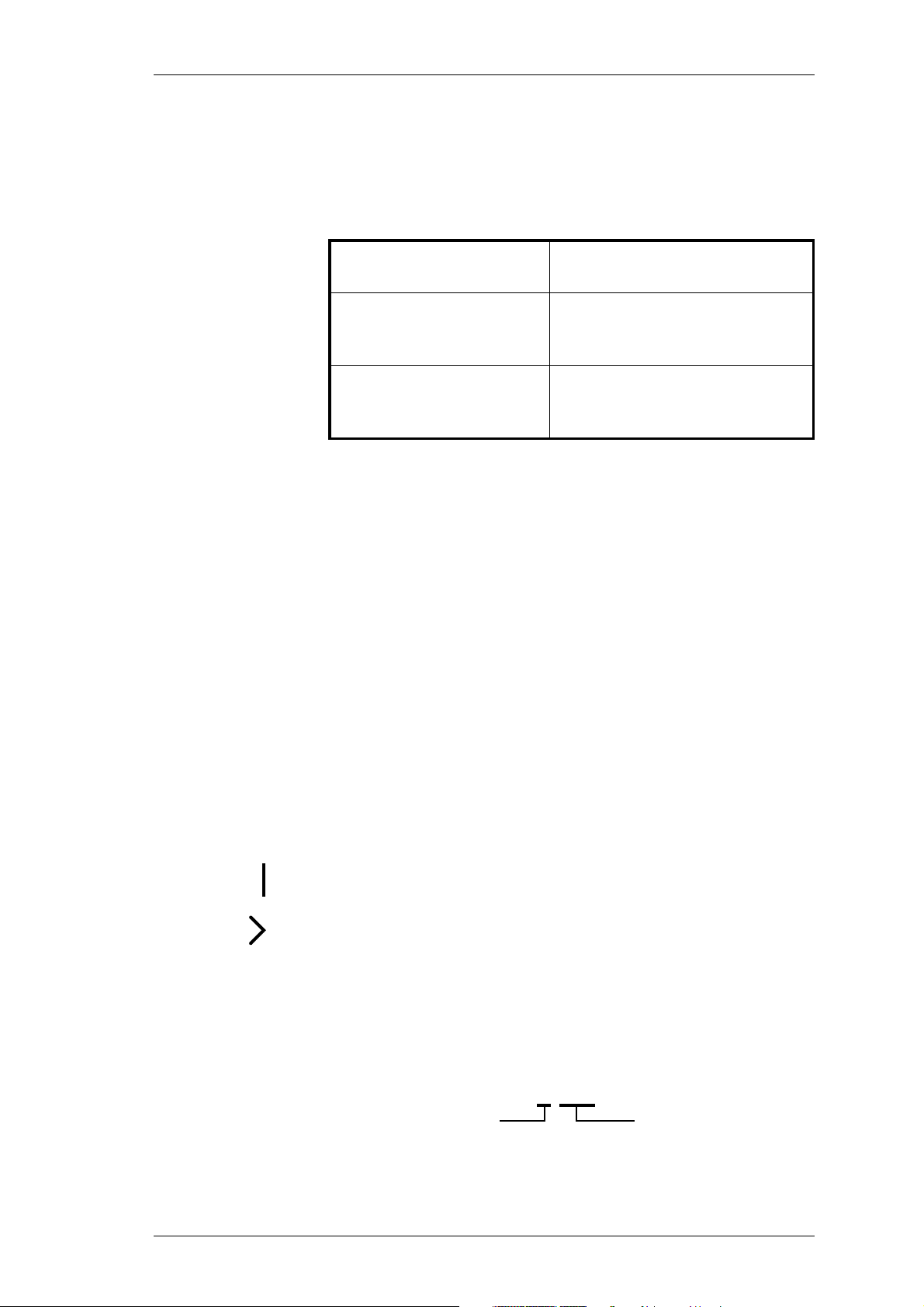
When requesting information, please quote either the manual product code (e.g.
M850-00-200), or the equipment product code and serial number which are printed on a
label on the back of the product (as shown in Figure 1.1).
this area used for regional
Type Approval information
T838-10-0000
Rev 1
900000
Tait Electronics Limited
Made in New Zealand
Figure 1.1 Typical Product Code & Serial Number Labels
product code
serial number
T835-10-0000 Rev 1
Tait Electronics Limited
Made in New Zealand
900000
If you require information about a particular PCB, please quote the full PCB internal
part number (IPN) which is screen printed onto the top side of the board (refer to the
appropriate PCB Information section in this manual for more details).
1.2 Caution: CMOS Devices
This equipment contains CMOS Devices which are susceptible to damage from static
charges. Care when handling these devices is essential. For correct handling procedures refer to the manufacturers' data books, e.g. Philips data books covering CMOS
devices, or Motorola CMOS data books, Section 5 'Handling', etc.
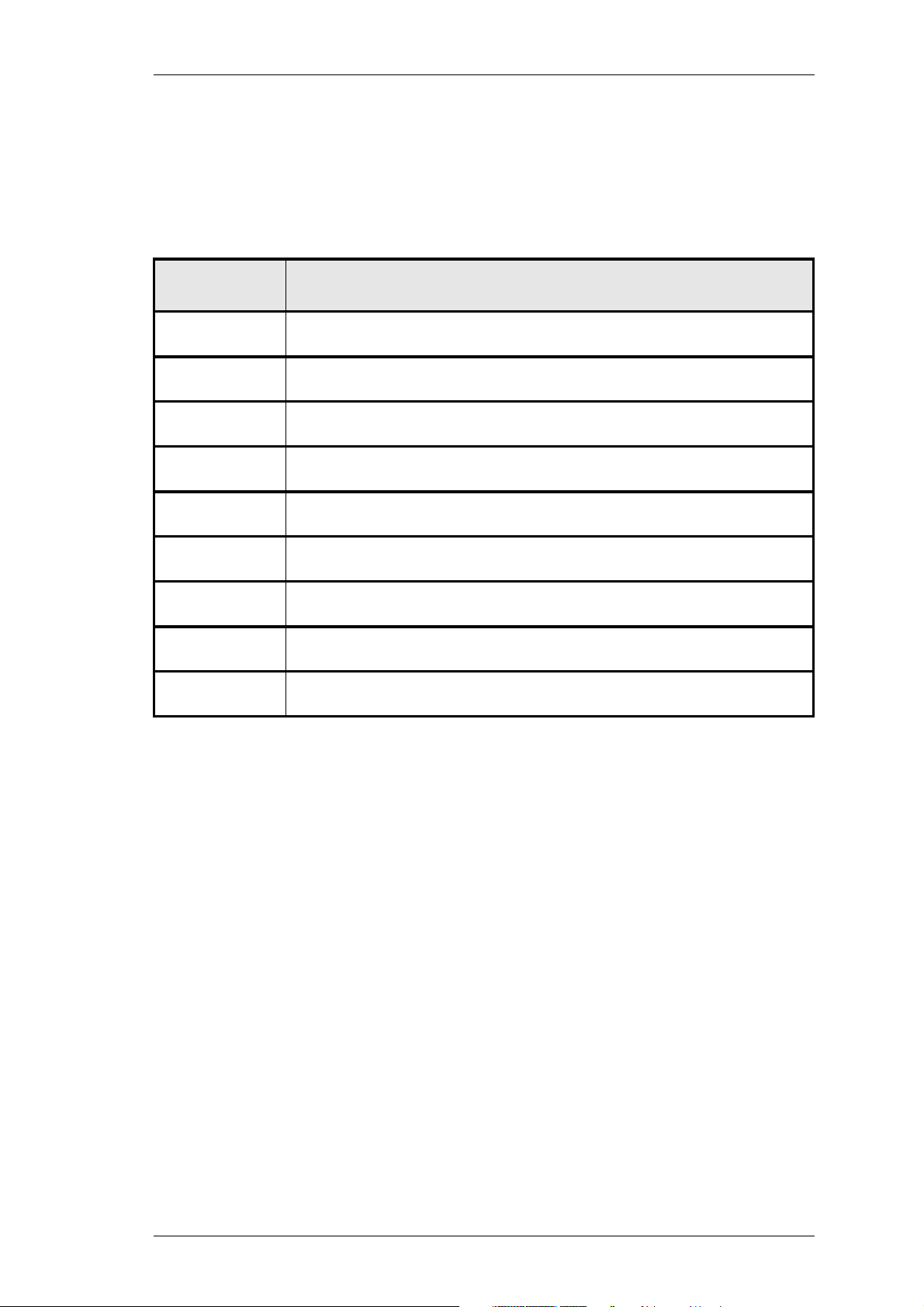
An anti-static bench kit (refer to Figure 1.2) is available from Tait Electronics Ltd under
the following product codes:
• KS0001 - 1 conductive rubber bench mat
- 1 earth lead to connect the mat to ground
• KS0004 - 1 wrist strap.
Copyright TEL 31/09/98
Page 16
A1.2
General
M850-00
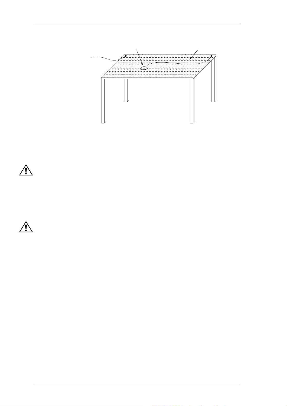
conductive
wrist strap
to building earth
(not mains earth)
Figure 1.2 Typical Anti-static Bench Set-up
1.3 Caution: Aerial Load
conductive rubber
bench mat
The equipment has been designed to operate safely under a wide range of aerial loading
conditions. However, we strongly recommend that the transmitter should always be
operated with a suitable load to prevent damage to the transmitter output power stage.
1.4 Caution: Beryllium Oxide & Power Transistors
The RF power transistors in current use all contain some beryllium oxide. This substance, while perfectly harmless in its normal solid form, can become a severe health
hazard when it has been reduced to dust. For this reason the RF power transistors
should not be broken open, mutilated, filed, machined, or physically damaged in any
way that can produce dust particles.
31/09/98 Copyright TEL
Page 17

M850-00
Mechanical
A2.1
2 Mechanical
2.1 Torx Recess Head Screws
Torx recess head screws are becoming the standard screw head type in all T800 Series II
equipment, with Pozidriv and Philips recess head screws being used in fewer applications.
The Torx recess head has the advantage of improved screwdriver tip location, reducing
the chances of screw head damage caused by the driver tip rotating within the recess. In
addition, using a ball-tip Torx screwdriver allows you to drive a Torx head screw with
the driver on a slight angle, which can be useful in situations where access is restricted.
It is important that you use the correct Torx screwdriver tip:
M3 screws - T10
M4 screws - T20.
Figure 2.1 below shows a typical Torx recess head screw (actual hardware may differ
slightly from this illustration due to variations in manufacturing techniques).
"star" shaped recess with
six internal notches
Figure 2.1 Torx Screw Identification
Copyright TEL 31/09/98
Page 18

A2.2
Mechanical
M850-00
2.2 Pozidriv & Philips Recess Head Screws
Pozidriv and Philips recess head screws will continue to be used in T800 Series II equipment in a few special applications. It is important that you use the correct type and size
screwdriver for each screw type to avoid damaging the screw head.
It is particularly important that you do not use Philips screwdrivers on Pozidriv screw
heads as the tapered driving flutes of the Philips screwdriver do not engage correctly
with the parallel-sided slots in the Pozidriv screw head. This can result in considerable
damage to the screw head if the screwdriver tip turns inside the recess.
Note:
If you find you need excessive downwards pressure to keep the screwdriver
tip in the Pozidriv screw head, you are probably using the wrong type and/
or size screwdriver.
Figure 2.2 below shows the main differences between typical Pozidriv and Philips screw
heads and screwdriver tips (actual hardware may differ slightly from these illustrations
due to variations in manufacturing techniques).
Pozidriv Philips
internal notches
no special markings
"star" markings
between slots
slots with parallel sides
slots with tapered sides
driving flutes with
parallel sides
driving flutes with
tapered sides
ridges between
driving flutes
Figure 2.2 Pozidriv & Philips Screw & Screwdriver Identification
31/09/98 Copyright TEL
Page 19

M850-00
Mechanical
A2.3
2.3 Disassembly/Reassembly
2.3.1 Receivers/Exciters/Transmitters
To carry out alignment or change option links, you need to remove only the top cover,
i.e. the one adjacent to the front panel handle and on the opposite side to the main
D-range connector (D-range 1/PL100).
You need to remove the bottom cover to:
• access transmitter RF power transistors and many SMD components
• change solder blob links
• fit test leads to circuit block access points.
2.3.2 Power Amplifiers
You should carry out the tuning and power output level setting procedures with the
cover on.
2.4 Cover Screw Torques
Receivers/Exciters/Transmitters .. 1.36Nm/12lb-in.
Power Amplifiers .. 0.9Nm/8lb-in.
Copyright TEL 31/09/98
Page 20

A2.4
Mechanical
M850-00
31/09/98 Copyright TEL
Page 21

M850-00
Component Replacement
A3.1
3 Component Replacement
3.1 Leaded Components
Whenever you are doing any work on the PCB that involves removing or fitting components, you must take care not to damage the copper tracks. The two satisfactory methods of removing components from plated-through hole (PTH) PCBs are detailed below.
Note:
The first method requires the use of a desoldering station, e.g. Philips SBC
314 or Pace MBT-100E.
3.1.1 Desoldering Iron Method
Place the tip over the lead and, as the solder starts to melt, move the tip in a circular motion.
Start the suction and continue the movement until 3 or 4 circles have been completed.
Remove the tip while continuing suction to ensure that all solder is removed from
the joint, then stop the suction.
Before pulling the lead out, ensure it is not stuck to the plating.
If the lead is still not free, resolder the joint and try again.
Note:
The desoldering iron does not usually have enough heat to desolder leads
from the ground plane. Additional heat may be applied by holding a soldering iron on the tip of the desoldering iron (this may require some additional help).
3.1.2 Component Cutting Method
Cut the leads on the component side of the PCB.
Heat the solder joint
out from the component side: do
Fill the hole with solder and then clear with solderwick.
Copyright TEL 31/09/98
sufficiently
to allow
not
easy
use undue force.
removal of the lead by drawing it
Page 22

A3.2
Component Replacement
3.2 Surface Mount Devices
M850-00
Caution:
Surface mount devices (SMDs) require special storage, handling,
removal and replacement techniques. This equipment should be serviced only by an approved Tait Dealer or Customer Service Organisation equipped with the necessary facilities. Repairs attempted with
incorrect equipment or by untrained personnel may result in permanent damage. If in doubt, contact your nearest Tait Dealer or Customer
Service Organisation.
3.3 Cased Mica Capacitors
Cased mica capacitors can be removed by heating the top with a heavy-duty soldering
iron and gently lifting the capacitor off the PCB with a solder-resistant spike or equivalent.
31/09/98 Copyright TEL
Page 23

M850-00
Software History
A4.1
4 Software History
28/06/96 PGM800Win Version 1.0
18/08/97 PGM800Win Version 2.00
4.1 PGM800Win V1.0
PGM800Win V1.0 is different in concept from DOS versions of PGM800 in that it is Win-
1
dows
PGM800.
The major changes are outlined below:
based. It also includes many new and improved features over DOS versions of
• The Windows
• PGM800Win includes several new radio models which are not programmable
with DOS versions of PGM800.
• Out of range frequencies will result in warning messages and will not be accepted
for entry into the standard library module. User defined modules can be created,
however, allowing variation from the standard library module.
• Channel numbers default to 0-127 to match the EPROM memory locations. However, the user can change this setting so that the channel numbers run from 1-128
to suit his/her particular needs.
Note:
The data files produced by BASEPROG V1.0 and all DOS versions of
PGM800 are still compatible with PGM800Win V1.0.
environment makes data entry and editing significantly easier.
4.2 PGM800Win V2.00
PGM800Win V2.00 is an upgraded and expanded version of PGM800Win V1.0. It has
been developed specifically for T800 Series II base stations, but retains the ability to program Series I equipment.
The major changes are outlined below:
• PGM800Win V2.0 will program T800 Series II base station modules via serial communications.
• Deviation and reference modulation settings are written automatically to the
radio.
1. Windows is a registered trademark of the Microsoft Corporation.
Copyright TEL 31/09/98
Page 24

A4.2
• Extra information that is not stored in the radio (but which is still relevant to the
Software History
radio) can be saved to a file on disk (e.g. note field, auxiliary pin names, etc.).
M850-00
Note:
The data files produced by BASEPROG V1.0, all DOS versions of PGM800,
and PGM800Win V1.0 are still compatible with PGM800Win V2.00.
31/09/98 Copyright TEL
Page 25

M850-00
BI
Part B T855 Receiver
This part of the manual is divided into six sections, as listed below. There is a detailed
table of contents at the start of each section.
Section Title
1 General Information
2 Circuit Operation
3 Initial Tuning & Adjustment
4 Functional Testing
5 Fault Finding
6 PCB Information
Copyright TEL 31/09/98
Page 26

BII
M850-00
31/09/98 Copyright TEL
Page 27
M850-00
T855 General Information
B1.1
1 T855 General Information
This section provides a brief description of the T855 receiver, along with detailed specifications and a list of types available.
The following topics are covered in this section.
Section Title Page
1.1 Introduction 1.5
1.2
1.2.1
1.2.2
1.2.3
1.2.4
1.2.4.1
1.2.4.2
1.2.4.3
1.2.5
1.2.6
1.2.6.1
1.2.6.2
1.2.6.3
1.3 Product Codes 1.12
1.4 Standard Product Range 1.13
Specifications
Introduction
General
RF Section
Audio Section
General
CTCSS
Mute Operation
Microprocessor Controller
Test Standards
European Telecommunication Standard (ETS)
DTI CEPT Recommendation T/R-24-01
Telecommunications Industry Association
1.6
1.6
1.7
1.7
1.9
1.9
1.9
1.10
1.10
1.10
1.10
1.11
1.11
Figure Title Page
1.1
1.2
Copyright TEL 31/09/98
T855 Main Circuit Block Identification
T855 Front Panel Controls
1.4
1.4
Page 28

B1.2
T855 General Information
M850-00
31/09/98 Copyright TEL
Page 29

M850-00
T855 General Information
replace A4 pages B1.3/B1.4 with A3 pages B1.3/B1.4
B1.3
Copyright TEL 31/09/98
Page 30

B1.4
T855 General Information
replace A4 pages B1.3/B1.4 with A3 pages B1.3/B1.4
M850-00
31/09/98 Copyright TEL
Page 31

M850-00
1.1 Introduction
T855 General Information
B1.5
The T855 is a high performance microprocessor controlled FM base station receiver
designed for single or multichannel operation in the 400 to 530MHz frequency range
The receiver is a dual conversion superhet with a synthesised local oscillator. The first
IF is 45.0MHz, allowing exceptionally high spurious signal rejection to be achieved in
the receiver front end. The second IF section (455kHz) combines amplitude limiting,
detection and audio preamplification within a single integrated circuit. It also drives
carrier and noise level detectors for signal strength indication and gating the audio output. RSSI can be used to drive a carrier mute for audio output gating (link selectable)
when the optional T800-04-0000 RSSI PCB is fitted.
The audio section output can be adjusted to deliver >+10dBm to a 600 ohm balanced
output, and 1W to a local monitor speaker. A flat or de-emphasised audio response is
link selectable.
The synthesiser frequency is programmed via the serial communications port. Eight
channel select lines are accessible via an additional D-range connector (D-range 2 T800-03-0000) at the rear of the set.
All components except those on the VCO board are mounted on a single PCB. This is
secured to a die-cast chassis which is divided into compartments to individually shield
each section of circuitry. Access to both sides of the main PCB is obtained by removing
each of the two chassis covers. There is provision within the chassis to mount small
option PCBs.
1
.
The front panel controls include gating sensitivity, line level, monitor volume and a
monitor mute switch.
The T855 has a width of 60mm and occupies a single space in a Tait rack frame, which
has the ability to accommodate up to seven standard modules.
1. Although capable of operating over the 400-530MHz frequency range, the T855 has a
5MHz switching range (see Section 1.2.3 and Section 3.1).
Copyright TEL 31/09/98
Page 32

B1.6
T855 General Information
M850-00
1.2 Specifications
1.2.1 Introduction
The performance figures given are minimum figures, unless otherwise indicated, for
equipment tuned with the maximum switching range and operating at standard room
temperature (+22°C to +28°C) and standard test voltage (13.8V DC).
Where applicable, the test methods used to obtain the following performance figures are
those described in the EIA and ETS specifications. However, there are several parameters for which performance according to the CEPT specification is given. Refer to Section 1.2.6 for details of test standards.
Details of test methods and the conditions which apply for Type Approval testing in all
countries can be obtained from Tait Electronics Ltd.
The terms "wide bandwidth", "mid bandwidth" and "narrow bandwidth" used in this
and following sections are defined in the following table.
Channel Spacing
Wide Bandwidth 25kHz ±5.0kHz 15.0kHz
Mid Bandwidth 20kHz ±4.0kHz 12.0kHz
Narrow Bandwidth 12.5kHz ±2.5kHz 7.5kHz
Sensitivity and distortion figures are stated for standard operating conditions which
includes audio de-emphasis. Note that the sensitivity and distortion figures will be
degraded when flat audio is selected.
Link PL210
De-emphasised Audio 1-2 (A-B) 2-3 (E-F)
Flat Audio 2-3 (B-C) 1-2 (D-E)
a. The letters in this column refer to the identification letters screen printed onto the PCB be-
side each set of links.
Modulation
100% Deviation
a
Receiver
IF Bandwidth
Link PL220
a
31/09/98 Copyright TEL
Page 33

M850-00
1.2.2 General
T855 General Information
B1.7
Number Of Channels .. 128 (standard)
Supply Voltage:
Operating Voltage .. 10.8 to 16V DC
Standard Test Voltage .. 13.8V DC
Polarity .. negative earth only
Polarity Protection .. diode
Supply Current:
Standby .. 350mA
Full Audio .. 750mA
Operating Temperature Range .. -20°C to +60°C
Dimensions:
Height .. 191mm
Width .. 60mm
Length .. 324mm
Weight .. 2.13kg
1
1.2.3 RF Section
Frequency Range .. 400-530MHz
Type .. dual conversion superheterodyne
Frequency Increment .. 5 or 6.25kHz
Switching Range .. 5MHz (i.e. ±2.5MHz from the centre
frequency)
Input Impedance .. 50 ohms
Frequency Stability .. ±1ppm, -20°C to +60°C
(see also Section 1.4)
Signal Strength Indicator .. -115dBm to -70dBm, 0 to 5V
(RSSI optional) at approx. 10dB/V
1. Additional channels may be factory programmed. Contact your nearest Tait Dealer or
Customer Service Organisation.
Copyright TEL 31/09/98
Page 34

B1.8
IF Amplifiers:
Sensitivity (De-emphasised Response):
Sensitivity (Flat Response):
Signal+Noise To Noise Ratio (Typical):
T855 General Information
Frequencies .. 45MHz and 455kHz
Bandwidths-
Narrow Bandwidth (NB) .. 7.5kHz
Mid Bandwidth (MB) .. 12kHz
Wide Bandwidth (WB) .. 15kHz
Single Channel .. -117dBm
Bandspread (12dB Sinad) .. -115dBm (across switching range)
Single Channel .. -111dBm
Bandspread (12dB Sinad) .. -109dBm
De-emphasised
RF Level -107dBm .. 30dB (WB) 20dB (WB)
25dB (NB) 15dB (NB)
M850-00
Flat
RF Level -83dBm (CEPT) .. 54dB (MB) 49dB (MB)
50dB (NB) 45dB (NB)
RF Level -57dBm (EIA) .. 55dB (WB) 55dB (WB)
Selectivity:
Narrow Bandwidth (±12.5kHz) .. 83dB minimum, 85dB typical (CEPT)
Mid Bandwidth (±20kHz) .. 87dB minimum, 90dB typical (CEPT)
Wide Bandwidth (±25kHz) .. 87dB minimum, 90dB typical (CEPT)
Offset Selectivity (Canada only) .. 20dB
Spurious Response Attenuation .. 100dB
Intermodulation Response Attenuation:
Narrow Bandwidth .. 80dB CEPT (typical)
Mid Bandwidth .. 75dB CEPT
Wide Bandwidth .. 85dB EIA
Blocking .. 100dB
Co-channel Rejection .. 6dB
Amplitude Characteristic .. 3dB
Spurious Emissions:
Conducted .. -90dBm to 4GHz
Radiated .. -57dBm to 1GHz
-47dBm to 4GHz
31/09/98 Copyright TEL
Page 35

M850-00
T855 General Information
1.2.4 Audio Section
1.2.4.1 General
Outputs Available .. line and monitor
Frequency Response .. flat or de-emphasised (750µs)
(link selectable)
Flat Response:
Bandwidth .. 67 to 3400Hz
Response .. within +1, -2dB of output level
at 1kHz
De-emphasised Response:
Bandwidth .. 300 to 3400Hz
Response .. within +1, -3dB of a -6dB/octave
de-emphasis characteristic (ref. 1kHz)
B1.9
Line Output:
Power .. adjustable to >+10dBm
Load Impedance .. 600 ohms
Distortion (@ -70dBm signal level):
De-emphasised
Wide Bandwidth .. ≤2% ≤2%
Mid & Narrow Bandwidth .. ≤2% ≤4%
1.2.4.2 CTCSS
Linkable High Pass Filter:
Bandwidth .. 350 to 3400Hz
Response .. within +1, -3dB of level at 1kHz
Hum And Noise .. 30dB min. at 250.3Hz
(1kHz at 60% system deviation 35dB typical (67 to 240Hz)
CTCSS at 10% system deviation)
Tone Detect:
Tone Squelch Opening .. better than 6dB sinad
3dB sinad at 250.3Hz (typical)
4dB sinad at 100Hz (typical)
Flat
Tone Detect Bandwidth .. ±2.1Hz accept (typical)
±3.0Hz reject (typical)
Response Time .. 150ms open and close (typical)
Copyright TEL 31/09/98
Page 36

B1.10
1.2.4.3 Mute Operation
Systems Available .. noise mute and carrier mute
Noise Mute:
Carrier Mute (Optional):
T855 General Information
Operating Range .. 6-20dB sinad
Hysteresis .. 1.5 to 6dB
Threshold .. adjustable to -105dBm
Opening Time .. 20ms
Closing Time .. 50ms
Operating Range .. -115 to -80dBm
Hysteresis .. 2 to 10dB
Opening Time .. 5ms
Closing Time .. 50ms
M850-00
Note:
The opening and closing times given above are for the standard setup
(SL210 linked and SL220 not linked - refer to Section 3.8).
1.2.5 Microprocessor Controller
Auxiliary Ports:
Open Drain Type .. capable of sinking 2.25mA via 2k2Ω
max. .. 5V
V
ds
1.2.6 Test Standards
Where applicable, this equipment is tested in accordance with the following standards.
1.2.6.1 European Telecommunication Standard
ETS 300 086 January 1991
Radio equipment and systems; land mobile service; technical characteristics and test
conditions for radio equipment with an internal or external RF connector intended primarily for analogue speech.
ETS 300 113 March 1996
Radio equipment and systems; land mobile service; technical characteristics and test
conditions for radio equipment intended for the transmission of data (and speech) and
having an antenna connector.
ETS 300 219 October 1993
Radio equipment and systems; land mobile service; technical characteristics and test
conditions for radio equipment transmitting signals to initiate a specific response in the
receiver.
31/09/98 Copyright TEL
Page 37

M850-00
ETS 300 279 February 1996
Radio equipment and systems; electromagnetic compatibility (EMC) standard for private land mobile radio (PMR) and ancillary equipment (speech and/or non-speech).
1.2.6.2 DTI CEPT Recommendation T/R-24-01
Annex I: 1988
Technical characteristics and test conditions for radio equipment in the land mobile
service intended primarily for analogue speech.
Annex II: 1988
Technical characteristics of radio equipment in the land mobile service with regard to
quality and stability of transmission.
1.2.6.3 Telecommunications Industry Association
T855 General Information
B1.11
ANSI/TIA/EIA-603-1992
Land mobile FM or PM communications equipment measurement and performance
standards.
Copyright TEL 31/09/98
Page 38

B1.12
T855 General Information
M850-00
1.3 Product Codes
The three groups of digits in the T850 Series II product code provide information about
the model, type and options fitted, according to the conventions described below.
The following explanation of T850 Series II product codes is not intended to suggest that
any combination of features is necessarily available in any one product. Consult your
nearest Tait Dealer or Customer Service Organisation for more information regarding
the availability of specific models, types and options.
Model
The Model group indicates the basic function of the product, as follows:
T85X
-XX-XXXX T855 receiver
T856 25W transmitter
T857 exciter
T858 50W power amplifier
T859 100W power amplifier
Type
The Type group uses two digits to indicate the basic RF configuration of the product.
The first digit in the Type group designates the frequency range:
T85X-X
The second digit in the Type group indicates the channel spacing:
T85X-XX
X-XXXX ’1’ for 400-440MHz
’2’ for 440-480MHz
’3’ for 480-520MHz
-XXXX ’0’ for wide bandwidth (25kHz)
’3’ for mid bandwidth (20kHz)
’5’ for narrow bandwidth (12.5kHz)
Options
T85X-XX-XXXX The Options group uses four digits and/or letters to indicate
any options that may be fitted to the product. This includes
standard options and special options for specific customers.
’0000’ indicates a standard Tait product with no options fitted.
The large number of options precludes listing them here.
31/09/98 Copyright TEL
Page 39

M850-00
T855 General Information
B1.13
1.4 Standard Product Range
The following table lists the range of standard T855 types (i.e. no options fitted) available at the time this manual was published. Consult your nearest Tait Dealer or Customer Service Organisation for more information.
Frequency Range (MHz) 400-440
IF Bandwidth (kHz) 7.5 12 15
TCXO ±1ppm -20°C to +60°C
Receiver Type: T855- 15-0000 13-0000 10-0000
Frequency Range (MHz) 440-480
IF Bandwidth (kHz) 7.5 12 15
TCXO ±1ppm -20°C to +60°C
Receiver Type: T855- 25-0000 23-0000 20-0000
Frequency Range (MHz) 480-530
IF Bandwidth (kHz) 7.5 15
TCXO ±1ppm -20°C to +60°C
Receiver Type: T855- 35-0000 30-0000
•••
•••
••
You can identify the receiver type by checking the product code printed on a label on
the rear of the chassis (Figure 1.1 in Part A shows typical labels). You can further verify
the receiver type by checking the placement of an SMD resistor in the table that is screen
printed onto the PCB (refer to Section 6.1 for more details).
Copyright TEL 31/09/98
Page 40

B1.14
T855 General Information
M850-00
31/09/98 Copyright TEL
Page 41

M850-00
T855 Circuit Operation
2 T855 Circuit Operation
This section provides a basic description of the circuit operation of the T855 receiver.
B2.1
Note:
Refer to Section 6 where the parts lists, grid reference index and diagrams will provide
detailed information on identifying and locating components and test points on the
main PCB. The parts list and diagrams for the VCO PCB are in Part E.
The following topics are covered in this section.
Unless otherwise specified, the term "PGM800Win" used in this and following sections refers to version 2.00 and later of the software.
Section Title Page
2.1 Introduction 2.3
2.2 Receiver Front End 2.4
2.3 Mixer 2.5
2.4 IF Circuitry 2.5
2.5 Noise Mute (Squelch) 2.6
2.6 Carrier Mute 2.6
2.7 Audio Processor 2.7
2.8 Power Supply And Regulators 2.8
2.9 Microcontroller 2.9
2.10 Synthesised Local Oscillator 2.10
2.11 VCO 2.11
2.12 Received Signal Strength Indicator (RSSI) 2.12
Figure Title Page
2.1
2.2
2.3
2.4
2.5
2.6
2.7
T855 High Level Block Diagram
T855 Front End, IF and Mute Block Diagram
T855 Audio Processor Block Diagram
T855 Power Supply And Regulators Block Diagram
T855 Microcontroller Block Diagram
T855 Synthesiser Block Diagram
T855 RSSI Block Diagram (T800-04-0000 RSSI PCB)
2.3
2.4
2.7
2.8
2.9
2.10
2.12
Copyright TEL 31/09/98
Page 42

B2.2
T855 Circuit Operation
M850-00
31/09/98 Copyright TEL
Page 43

M850-00
2.1 Introduction
T855 Circuit Operation
Noise
Mute
B2.3
Mixer Mixer Limiter
Front
End
Synthesised
Local
Oscillator
45MHz
IF
Second
Local
Oscillator
12.8MHz
Master
Oscillator
455kHz
IF
Figure 2.1 T855 High Level Block Diagram
The T855 receiver consists of a number of distinct stages:
• front end
•mixer
• synthesised local oscillator
•IF
• audio processor
• mute (squelch)
FM
Detector
RSSI
Audio
Processor
Carrier
Mute
Speaker
600Ω
}
Line
• regulator circuits
• received signal strength indicator (RSSI).
These stages are clearly identifiable in Figure 2.1. Refer to the circuit diagrams in Section 6 for further detail.
Copyright TEL 31/09/98
Page 44

B2.4
T855 Circuit Operation
M850-00
2.2 Receiver Front End
(Refer to the front end, IF section and audio processor circuit diagrams (sheets 4, 3 and 2
respectively) in Section 6.3.)
Local Oscillator
(From Synthesiser)
RF In
400-530MHz
Harmonic
Filter
Helical
Filter
RF
Amp
Helical
Filter
4dB Pad
Diplexer
Post
Mixer
Amp
4-Pole
Crystal
Filter
IF
Amp
2-Pole
Crystal
Filter
45MHz
Active
FilterLFAmp
Diode
Detector
Gain
Adjust
IF
Amp
2nd LO
44.545MHz
Smoothing
Mixer
(MC3361)
Filter
Mixer
Ceramic
Filter
455kHz
Link:
Comparator
Limiter
(MC3361)
RSSI
Carrier Mute
Noise Mute
Mute
Adjust
45MHz
Detector
(MC3361)
Buffer
Amp
Comparator
Gating
Delays
FM
t∆
Low
Pass
Filter
Mute
Adjust
Comparator
Buffer
Amp
Audio
(To Audio
Processor)
RSSI Output
Voltage
(To D-Range
Connector)
Rx Gate Out
(To Audio
Processor)
Audio Section
Figure 2.2 T855 Front End, IF and Mute Block Diagram
The incoming signal from the N-type antenna socket is fed through a 9-pole, low pass
filter with a cut frequency of approximately 600MHz. This low loss filter (typically less
than 0.5dB over 400-530MHz) provides excellent immunity to interference from high
frequency signals.
The signal is then further filtered, using a high performance helical resonator doublet
(FL410) which provides exceptional image rejection, before being amplified by approximately 8dB (Q410). The signal is then passed through a further helical filter doublet
(FL420) before being presented to the mixer via a 2dB attenuator pad.
Each sub-block within the front end has been designed with 50 ohm terminations for
ease of testing and fault finding. The overall gain from the antenna socket to the mixer
input is approximately 2dB.
31/09/98 Copyright TEL
Page 45

M850-00
T855 Circuit Operation
B2.5
2.3 Mixer
(Refer to the front end circuit diagram (sheet 4) in Section 6.3 and Figure 2.2.)
IC410 is a high level mixer requiring a local oscillator (LO) drive level of +17dBm (nominal). The voltage controlled oscillator (VCO) generates a level of +21dBm (typical) and
this is fed to the mixer via a 5dB attenuator pad. A diplexer terminates the IF port of the
mixer in a good 50 ohms, thus preventing unnecessary intermodulation distortion.
2.4 IF Circuitry
(Refer to the IF section circuit diagram (sheet 3) in Section 6.3 and Figure 2.2.)
Losses in the mixer are made up for in a tuned, common gate, post mixer amplifier
(Q310). Several stages of amplification and filtering are employed in the IF circuitry.
The first crystal filter is a 4-pole device (&XF300) which is matched into 50 ohms on both
its input and output ports. This stage is followed by a common base amplifier (Q320)
whose output is matched into a 2-pole crystal filter (&XF301). The signal is then amplified using a high gain MOSFET amplifier (Q330), after which the signal is mixed down
to 455kHz with the second crystal local oscillator (44.5455MHz).
The 455kHz signal is filtered using a 6-pole ceramic filter (&XF302) before being limited
and detected. Q340 provides a buffered 455kHz output for use with the optional RF
level detector (RSSI)
The second IF mixer, limiter and detector is in a 16-pin IC (IC310). Quadrature detection
is employed, using L390, and the recovered audio on pin 9 of IC310 is typically 1V p-p
for 60% system deviation.
Copyright TEL 31/09/98
Page 46

B2.6
T855 Circuit Operation
M850-00
2.5 Noise Mute (Squelch)
(Refer to the audio processor and IF section circuit diagrams (sheets 2 and 3 respectively) in Section 6.3 and Figure 2.2.)
The noise mute operates on the detected noise outside the audio bandwidth. An operational amplifier in IC310 is used as an active band pass filter centred on 70kHz to filter
out audio components. The noise spectrum is then further amplified in a variable gain,
two-stage amplifier (Q350 & Q360) with additional filtering. The noise is then rectified
(D310) and filtered to produce a DC voltage proportional to the noise amplitude. The
lowest average DC voltage corresponds to a high RF signal strength and the highest DC
voltage corresponds to no signal at the RF input.
The rectified noise voltage is compared with a threshold voltage set up on RV230, the
front panel "Gating Sensitivity" potentiometer. Hysteresis is provided by the feedback
resistor (R267) to prevent the received message from being chopped when the average
noise voltage is close to the threshold. R281 and R280 determine the mute opening and
closing times and, in combination with solder links SL210 and SL220, provide three time
delay options (SL210 is linked as standard - refer to Section 3.8). The mute control signal
at pin 7 of IC270 is used to disable the speaker and line audio outputs. The speaker output can be separately enabled for test purposes by operating the front panel mute disable switch, SW201.
2.6 Carrier Mute
(Refer to the audio processor and IF section circuit diagrams (sheets 2 and 3 respectively) in Section 6.3 and Figure 2.2.)
A high level carrier mute facility is also available. The RSSI (refer to Section 2.12) provides a DC voltage proportional to the signal strength. This voltage is compared with a
preset level, set up on RV235, and may be linked into the mute timing circuit using
PL250. PL250 selects either the noise mute or the carrier mute. From this point both the
noise and carrier mute circuits operate in the same manner, using common circuitry.
31/09/98 Copyright TEL
Page 47

M850-00
T855 Circuit Operation
2.7 Audio Processor
(Refer to the audio processor circuit diagram (sheet 2) in Section 6.3.)
B2.7
From
IF Stage
Demodulated
Signal
Flat/De-
emphasis
*IF
Comp
(*IF Audio
Compensation
Circuit)
PL210
2
3
LPF
Flat/De-
emphasis
Amplifier
PL220
2
1
3
Audio 1
Output
High Pass
Filter
Audio 2
Input
RSSI
(Optional)
Speech
PL240
1
2
3
4
5
1
2
3
PL230
Carrier
Mute
Noise
Mute
Monitor
Volume
Line
Level
PL250
3
2
1
PL260
12
Speaker
Mute
Line
Mute
PL270
1
2
Driver Amp
12V
Relay
Rx Disable
Timer
Driver Amp
Figure 2.3 T855 Audio Processor Block Diagram
The recovered audio on pin 9 of IC310 is passed through a compensation network and
processed in a third order elliptic active filter to give the required response. Linking
(PL220 & PL210) is available to give either a flat or de-emphasised audio response, with
de-emphasis giving a -6dB/octave roll off. The output of IC210 is split to provide separate paths for the speaker and line outputs. The "Audio 1", Audio 2" and "Speech" lines
allow access to the receiver’s audio path for external signalling purposes (refer to Section 3.5).
RSSI Output
Mute Relay
Gate Output
Rx Disable
(Optional Pad)
Mute Disable
Speaker Output
Line Output
Line Monitor
The signals are passed to audio drive amplifiers IC240 and IC260. Under muted conditions the inputs of these amplifiers are shunted to ground via transistors Q230 and Q290
respectively. The audio output of IC240 has a DC component which is removed by
C249, and this then drives a speaker directly. The output of IC260 is fed into a line transformer to provide a balanced 2-wire or 4-wire, 600 ohm output.
The speaker volume is set using the front panel "Monitor Volume" knob (RV205) and the
line level is set using the recessed "Line Level" potentiometer (RV210).
The red front panel "Gate" LED (D250) indicates the status of the mute circuit. When a
signal above the mute threshold is received, the LED is illuminated. The "Monitor
Mute" switch (SW201) on the front panel opens the mute, allowing continuous monitoring of the audio signal (on = audio muted; off = audio unmuted).
The mute control line is available on pad 234 ("RX GATE OUT") for control of external
circuitry. A high (9V) on pad 234 indicates that the audio is disabled and a low (0V)
indicates that a signal above the mute threshold level is being received.
Copyright TEL 31/09/98
Page 48

B2.8
T855 Circuit Operation
M850-00
The audio can also be disabled using the "RX-DISABLE" inputs, pads 225 or 228, having
connected the "RX-DISABLE" link between pins 1 & 2 of PL260. An adjustable time
delay (RV220) is provided on these lines. In order to disable the audio, either pad must
be pulled to 0V (refer to Section 1.4 in Part G).
An undedicated relay is provided (RL210) for transmitter keying or other functions and
this can be operated from the mute line by linking PL270.
2.8 Power Supply And Regulators
(Refer to the regulators circuit diagram (sheet 6) in Section 6.3.)
13.8V Nom.
From Rear
D-Range 1
DC
5V
Reg
Amp
Switching
PS
5V Dig
Reg
LVI
LVI
µP
Reset
13.8V
Nom.
5V 5V Dig9V 20V
Figure 2.4 T855 Power Supply And Regulators Block Diagram
The T855 is designed to operate off a 10.8-16V DC supply (13.8V nominal). A 5.3V regulator (IC630) runs directly from the 13.8V rail, driving much of the synthesiser circuitry.
It is also used as the reference for a DC amplifier (IC640, Q630 & Q620) which provides
a medium current capability 9V supply.
A switching power supply, based on Q670 and Q660, runs off the 9V supply and provides a low current capability +20V supply. This is used to drive the synthesiser loop
filter (IC740), giving a VCO control voltage of up to 20V.
The 13.8V supply drives both output audio amplifiers without additional regulation. A
separate 5V regulator (IC610) drives the microprocessor and associated digital circuitry.
The output of this regulator is monitored by the Low Voltage Interrupt (LVI) circuit
(IC650).
31/09/98 Copyright TEL
Page 49

M850-00
T855 Circuit Operation
2.9 Microcontroller
(Refer to the microcontroller circuit diagram (sheet 8) in Section 6.3.)
B2.9
Watchdog Timer
& LVI
Watchdog
EEPROM
Microcontroller Cavity
Channel
Select
Port
Auxiliary
Output
Port
Synthesiser
12.8MHz
Clock
External
Serial
Port
Audio In
Speech
5V Digital
Regulator
5V Reset
Microcontroller
Converter
CTCSS
Decoder
Figure 2.5 T855 Microcontroller Block Diagram
Overall system control of the T855 is accomplished by the use of a member of the 80C51
family of microcontrollers (IC810) which runs from internal ROM and RAM. Four ports
are available for input/output functions.
Non-volatile data storage is achieved by serial communication with a 16kBit EEPROM
(IC820). This serial bus is also used by the microcontroller to program the synthesiser
(IC740).
The main tasks of the microcontroller are as follows:
• program the synthesiser;
• interface with the PGM800Win programming software at 9600 baud via the
serial communication lines on D-range 1 (PL100) & D-range 2;
• monitor channel change inputs from D-range 2;
• generate timing waveforms for CTCSS detection;
• coordinate and implement timing control of the receiver.
Copyright TEL 31/09/98
Page 50

B2.10
T855 Circuit Operation
M850-00
2.10 Synthesised Local Oscillator
(Refer to the synthesiser circuit diagram (sheet 7) in Section 6.3 and the VCO circuit diagram in Part E.)
12.8MHz
Reference
Oscillator
Serial
Bus
FREQUENCY SYNTHESISER IC
Reference
Divider
/R
f
ref
Clk
Data
En
Controller
Phase
Detector
Charge
Pump
Programmable
Divider
/N
Loop
Filter
Prescaler
64/65
VCO Buffer
f
in
Buffer
VCO PCB
Output
Buffer
+22dBm
L.O.
Figure 2.6 T855 Synthesiser Block Diagram
The synthesiser (IC740) employs a phase-locked loop (PLL) to lock a voltage controlled
oscillator (VCO) to a given reference frequency. The synthesiser receives the divider
information from the control microprocessor via a 3-wire serial bus (clock, data, enable).
When the data has been latched in, the synthesiser processes the incoming signals from
the VCO buffer (f
) and the reference oscillator (f
in
ref
).
A reference oscillator at 12.8MHz (IC700) is buffered (IC710) and divided down to
6.25kHz or 5kHz within the synthesiser IC (IC740).
A buffered output of the VCO is divided with a prescaler and programmable divider
which is incorporated into the synthesiser chip (IC740). This signal is compared with
the reference signal at the phase detector (also part of the synthesiser chip). The phase
detector outputs drive a balanced charge pump circuit (Q760, Q770, Q775, Q780, Q785)
and active loop filter (IC750, Q790) which produces a DC voltage between 0V and 20V
to tune the VCO. This VCO control line is further filtered to attenuate noise and other
spurious signals. Note that the VCO frequency increases with increasing control voltage.
31/09/98 Copyright TEL
Page 51

M850-00
T855 Circuit Operation
B2.11
2.11 VCO
(Refer to the VCO circuit diagram in Part E.)
The VCO transistor (Q1) operates in a common emitter, and uses a transmission line resonator (TL1). The transmission line is used in a two port configuration with varicaps
positioned at one end. The VCO control voltage from the loop filter (IC750) is applied to
the varicaps (D1 & D2) to facilitate tuning. The VCO output is coupled into a cascode
amplifier stage (Q2 & Q3) which supplies +10dBm (nominal) output. Further amplification in Q5 brings the output drive level to +20dBm to drive the mixer.
A low level "sniff" is taken from the input to Q5 to drive the divider buffer to the synthesiser (IC740).
The VCO operates at the actual frequency required by the first mixer, i.e. there are no
multiplier stages.
The VCO frequency spans from either 355-395MHz, 395-435MHz or 435-485MHz
according to product type (refer to Section 1.4). The VCO is tuned to 45MHz below the
desired receive frequency (low side injection) to produce a 45MHz IF signal at the output of the mixer.
Copyright TEL 31/09/98
Page 52

B2.12
T855 Circuit Operation
M850-00
2.12 Received Signal Strength Indicator (RSSI)
(Refer to the T800-04-0000 RSSI PCB circuit diagram in Section 6.2 and the IF section circuit diagram (sheet 3) in Section 6.3.)
The RSSI option PCB plugs directly into the main PCB (support circuitry being fitted as
standard). It is fitted to the T855 whenever receiver signal strength monitoring is
required, e.g. trunking or voting. Its function is to provide a DC voltage proportional to
the signal level at the receiver input. The DC voltage is available at D-range 1 (PL100
pin 5).
The RSSI also provides the capability for high level signal strength muting, which may
be selected on PL250 (refer to Section 3.5). The mute threshold may be set between
-115dBm and -70dBm by RV235.
+V
Amp Detector Error Amp
RSSI
Input
Temp
Comp
Q1D
Q1C Q1A &
Variable
Gain Stage
Q1E
Temp Comp
DC Amp
(Gain= x33)
Q1B
VDC
RSSI Output
1V/10dB
NTC
DC Offset
(Ref)
Figure 2.7 T855 RSSI Block Diagram (T800-04-0000 RSSI PCB)
The variable gain stage (Q1A) is a common emitter amplifier with its emitter grounded
and the AGC control loop voltage applied to its base. Since the AGC loop will maintain
a constant signal level at the collector, the gain of Q1 must be proportional to the incoming 455kHz signal level. The gain of Q1 is linearly proportional to its collector current
which itself is exponentially related to the base-emitter voltage. Thus there is a logarithmic relationship between the base-emitter voltage and the gain. The circuit therefore
produces a feedback voltage, and an output voltage, logarithmically related to the RF
input signal.
The AGC loop is followed by a DC amplifier which provides level shifting, temperature
compensation and gain to give a nominal 1V/10dB at the RSSI output. RV320 on the
main PCB is used to set the RSSI voltage to a fixed value at a given RF input signal
strength.
31/09/98 Copyright TEL
Page 53

M850-00
T855 Initial Tuning & Adjustment
3 T855 Initial Tuning & Adjustment
B3.1
Caution:
The following section describes both short and full tuning and adjustment procedures
and provides information on:
• channel programming
• selecting the required audio links
• synthesiser alignment
• receiver front end and IF alignment
• noise and carrier level mute adjustment
• setting the line and monitor output levels
• setting up the RSSI.
Note:
Refer to Figure 4.3 which shows the location of the main tuning and adjustment controls. Refer also to Section 6 where the parts lists, grid reference index and diagrams
will provide detailed information on identifying and locating components and test
points on the main PCB. The parts list and diagrams for the VCO PCB are in Part E.
This equipment contains CMOS devices which are susceptible to damage from static charges. Refer to Section 1.2 in Part A for more information on anti-static procedures when handling these devices.
Unless otherwise specified, the term "PGM800Win" used in this and following sections refers to version 2.00 and later of the software.
Section Title Page
3.1 Introduction 3.3
3.2 Channel Programming 3.3
3.3 Test Equipment Required 3.4
3.4
3.4.1
3.4.2
3.4.3
3.4.4
3.4.4.1
3.4.4.2
3.4.5
3.4.6
3.4.6.1
3.4.6.2
3.4.6.3
3.4.7
Short Tuning Procedure
Introduction
Synthesiser Alignment
Front End Alignment
Mute Adjustment
Noise Mute
Carrier Level Mute
Line Amplifier Output
CTCSS
Decoder Operation
Opening Sinad
High Pass Filter
RSSI (If Fitted)
3.5
3.5
3.5
3.5
3.6
3.6
3.6
3.6
3.7
3.7
3.7
3.7
3.8
Copyright TEL 31/09/98
Page 54

B3.2
T855 Initial Tuning & Adjustment
Section Title Page
M850-00
3.5
3.5.1
3.5.2
3.6 Synthesiser Alignment 3.10
3.7 Alignment Of Receiver Front End And IF 3.10
3.8 Gating Delay 3.12
3.9 Noise Mute Adjustment 3.12
3.10 Carrier Level Mute 3.12
3.11
3.11.1
3.11.2
3.12
3.12.1
3.12.2
3.12.3
Audio Processor Links
General
Audio Processor Linking Details For CTCSS
Audio Processor
Line Amplifier Output
Monitor Amplifier Output (Speaker Output)
CTCSS
Decoder Operation
Opening Sinad
High Pass Filter
3.8
3.8
3.9
3.13
3.13
3.13
3.13
3.13
3.13
3.14
3.13 RSSI 3.14
Figure Title Page
3.1
3.2
T855 Test Equipment Set-up For Short Tuning Procedure
T855 Test Equipment Set-up For Full Tuning & Adjustment
Procedure
3.4
3.4
31/09/98 Copyright TEL
Page 55

M850-00
3.1 Introduction
T855 Initial Tuning & Adjustment
B3.3
When you receive your T855 receiver it will be run up and working on a particular frequency (the "default channel")
5MHz switching range (i.e. ±2.5MHz from the factory programmed frequency), you
should only need to reprogram the receiver with the PGM800Win software (refer to the
PGM800Win programming kit and Section 3.2 below).
However, if you want to switch to a frequency outside the 5MHz switching range, you
will have to reprogram and re-tune the receiver to ensure correct operation. In this case
you should carry out the short tuning procedure described in Section 3.4.
If you have carried out repairs or other major adjustments, you must carry out the full
tuning and adjustment procedure described in this section (except for Section 3.4).
1
. If you want to switch to a frequency that is within the
3.2 Channel Programming
You can program up to 128 channel frequencies into the receiver’s EEPROM memory
(IC820) by using the PGM800Win software package and an IBM
PGM800Win to select the receiver’s current operating frequency (or "default channel").
If the receiver is installed in a rack frame, you can program it via the programming port
in the speaker panel. However, you can also program the receiver before it is installed
in a rack frame as follows:
PC. You can also use
• by using a T800-01-0010 calibration test unit;
• via D-range 1;
• via D-range 2 (standard T800-03-0000 auxiliary D-range only);
• via SK805 (internal Micromatch connector).
If you do not use the T800-01-0010, you will have to connect the PC to the receiver via a
module programming interface (such as the T800-01-0004).
For a full description of the channel programming procedure, refer to the PGM800Win
programming software user’s manual.
Note:
When an auxiliary D-range kit (D-range 2 - T800-03-0000) is fitted, you can
also select a channel with an external switch, such as the DIP switch on the
rack frame backplane PCB. Refer to Part C in the T800 Series Ancillary
Equipment Service Manual (M800-00-101 or later issue) or consult your
nearest Tait Dealer or Customer Service Organisation for further details.
1. Use the "Read Module" function in PGM800Win to find out what the default channel is.
Copyright TEL 31/09/98
Page 56

B3.4
T855 Initial Tuning & Adjustment
3.3 Test Equipment Required
You will need the following test equipment:
• computer with PGM800Win installed
• T800 programming kit
• module programming interface (e.g. T800-01-0004 - optional)
• 13.8V power supply
• digital multimeter
• audio signal generator
M850-00
• RF signal generator
or RF test set (optional)
• audio voltmeter
• sinad meter
• oscilloscope
not needed for short tuning procedure
• distortion meter
• T800-01-0010 calibration test unit (optional)
•4Ω speaker (not needed if the calibration test unit is used)
Figure 3.1 and Figure 3.2 show
typical test equipment set-ups
(with and without a T800-01-0010
calibration test unit).
RF Signal
Generator
Audio Signal
Generator
PGM800Win
PSU
External
Modulation
+13.8V
-Ve
RF In
Receiver
T800
Calibration
Test Unit
Line
Line
Sinad
Meter
Audio
Voltmeter
Figure 3.1 T855 Test Equipment Set-up For Short Tuning Procedure
PSU
RF Signal
Generator
External
Modulation
Audio Signal
Generator
PGM800Win
+13.8V
-Ve
RF In
Receiver
GND
via module programming interface
Serial
(e.g. T800-01-0004)
Com
Line
Line
Speaker
Output
600Ω
Distortion
Meter
Sinad
Meter
Audio
Voltmeter
Oscilloscope
CH1
GND
(Or 4Ω Resistor)
CH2
Probe
4Ω Speaker
Figure 3.2 T855 Test Equipment Set-up For Full Tuning & Adjustment Procedure
31/09/98 Copyright TEL
Page 57

M850-00
T855 Initial Tuning & Adjustment
B3.5
3.4 Short Tuning Procedure
Use this procedure only if you want to reprogram the receiver to a frequency outside the
5MHz switching range and do not intend to carry out any other major adjustments or
repairs.
3.4.1 Introduction
Reprogram the operating frequency as described in the PGM800Win programming kit (refer to Section 3.2).
Remove the top cover (nearest the handle).
Set up the test equipment as described in Section 3.3.
Set the links in the audio processor section as required (refer to Section 3.5).
3.4.2 Synthesiser Alignment
• Connect a high impedance voltmeter to the long lead of L1 in the VCO (this meas-
ures the synthesiser loop voltage).
• Single Channel Tune VCO trimmer C6 for a synthesiser loop voltage of
10V.
Multichannel Tune VCO trimmer C6 for a synthesiser loop voltage of
10V on the middle channel.
If there is no middle channel, tune C6 so that the channels
are symmetrically placed around a loop voltage of 10V.
All channels should lie within the upper and lower limits
of 16V and 3V respectively.
Do not attempt to program channels with a greater fre-
quency separation than the specified switching range of
5MHz.
3.4.3 Front End Alignment
Note 1:
Note 2:
Copyright TEL 31/09/98
In this and following sections deviation settings are given first for wide
bandwidth sets, followed by settings in brackets for mid bandwidth sets ( )
and narrow bandwidth sets [ ].
For multichannel operation align the receiver on a frequency in the middle
of the required band.
Inject a strong on-channel RF signal with ±3kHz deviation (±2.4kHz) [±1.5kHz] at
1kHz into the antenna socket and adjust the helical resonators #FL410 & #FL420 to
give best sinad.
Page 58

B3.6
T855 Initial Tuning & Adjustment
Continually decrease the RF level to maintain 12dB sinad.
Readjust FL410 and FL420 to give best sinad.
With PL210 and PL220 connected for de-emphasised audio response, the receiver
sensitivity should be better than -117dBm, assuming that the audio levels are not
being overdriven (refer to Section 3.4.5).
3.4.4 Mute Adjustment
3.4.4.1 Noise Mute
Connect pins 1 & 2 of PL250 to enable the noise mute.
Set the RF level to -105dBm with ±3kHz deviation (±2.4kHz) [±1.5kHz] at 1kHz.
Set RV230 (front panel gating sensitivity) fully anticlockwise.
M850-00
Adjust RV310 (noise mute gain) to close the mute (if necessary turn off the RF signal and then turn it on again).
Rotate RV310 anticlockwise until the mute just opens.
Adjust RV230 for the required opening sinad.
3.4.4.2 Carrier Level Mute
Connect pins 2 & 3 of PL250 to enable the carrier mute and disable the noise mute.
Apply an on-channel signal from the RF generator at the required mute opening
level with ±3kHz deviation (±2.4kHz) [±1.5kHz] at ±1kHz.
Adjust RV235 (carrier mute) to close the mute (if necessary, momentarily turn off
the RF), then slowly adjust it until the mute just opens. The mute should now
open at this preset level.
3.4.5 Line Amplifier Output
Apply an on-channel signal from the RF generator at a level of -70dBm with
±3kHz deviation (±2.4kHz) [±1.5kHz] at 1kHz.
Adjust RV210 (front panel line level) to set the line level to the required output
level.
31/09/98 Copyright TEL
Page 59

M850-00
T855 Initial Tuning & Adjustment
3.4.6 CTCSS
3.4.6.1 Decoder Operation
Program a CTCSS tone on the set channel using PGM800Win.
Set the RF signal generator output to -70dBm.
Modulate the generator with:
• a 1kHz tone at ±3kHz deviation (±2.4kHz) [±1.5kHz]
• a CTCSS tone at the programmed frequency at ±500Hz deviation (±400Hz)
[±300Hz].
Check that the receiver gate opens and the front panel "Gate" LED is on.
3.4.6.2 Opening Sinad
B3.7
Adjust RV230 (front panel gating sensitivity) fully clockwise.
Reduce the RF signal level to -110dBm.
Observe the sinad meter and reduce the RF level until the receiver mute closes.
Slowly increase the signal level until the receiver mute just opens and stays open.
With PL240 pins 1 & 2 linked (G - H; high pass filter bypassed), check that the
sinad is less than 6dB.
Reset RV230.
3.4.6.3 High Pass Filter
Set the audio processor links as follows:
Plug Link Function
PL210 1 - 2 A - B de-emphasised response
PL230 2 - 3 N - P audio from internal CTCSS speech filter
PL240 4 - 5 K - L audio input via PL230 or I/O pad
Reset the RF signal generator output to -70dBm and note the line level (measurement A).
Reduce the 1kHz generator to zero output and measure the line level again (measurement B).
Check that measurement B is at least 30dB below measurement A.
Copyright TEL 31/09/98
Page 60

B3.8
T855 Initial Tuning & Adjustment
M850-00
3.4.7 RSSI (If Fitted)
The T800-04-0000 RSSI is an optional PCB which adds signal strength monitoring and
high level mute facilities to the basic receiver.
Ensure the T800-04-0000 PCB is fitted in SK320 and SK330 in the IF compartment.
Apply an on-channel signal from the RF generator at a level of -100dBm with
±3kHz deviation (±2.4kHz) [±1.5kHz] at 1kHz.
Adjust RV320 (RSSI level) to give 2.0V RSSI output on pin 5 of D-range 1 (PL100)
when measured with a high impedance DMM.
3.5 Audio Processor Links
3.5.1 General
Use the following table to set up the audio processor to the configuration you require.
You should set the audio processor links before carrying out the receiver alignment.
The factory settings are shown in brackets [ ].
Plug Link
PL210
PL220
PL230*
PL240
PL250
b
[1 - 2]
2 - 3
1 - 2
[2 - 3]
1 - 2
[2 - 3]
3 - 4
1 - 2
[2 - 3]
or
3 - 4
4 - 5
[1 - 2]
2 - 3
a
[A - B]
B - C
D - E
[E - F]
M - N
[N - P]
P - Q
G - H
[H - J]
or
J - K
K - L
[R - S]
S - T
Function
de-emphasised response
flat response
flat response
de-emphasised response
audio input via AUDIO-2 pad
audio from internal CTCSS speech filter
audio input via I/O pad P250
bypass high pass filter
300Hz high pass filter in circuit
audio input via PL230 or I/O pad
noise mute
carrier mute
PL260
PL270
a. The letters in this column and in the table in Section 3.5.2 below refer to the identification
letters screen printed onto the PCB beside each set of pins.
b. Refer to Section 3.5.2 for further details.
31/09/98 Copyright TEL
1 - 2
[2 - 3]
[1 - 2]
2 - 3
U - V
[V - W]
[X - Y]
Y - Z
RX-DISABLE link
not connected
relay link
not connected
Page 61

M850-00
T855 Initial Tuning & Adjustment
B3.9
3.5.2 Audio Processor Linking Details For CTCSS
You must connect the audio processor links correctly according to the CTCSS option
used, as shown in the table below.
CTCSS Option PL230 PL240
standard, no CTCSS 2 - 3 N - P 2 - 3 H - J
received CTCSS + speech
passed to line output
high pass filtered speech,
internal CTCSS detection
external CTCSS detection 1 - 2 M - N 4 - 5 K - L
The conditions stated in the above table are defined as follows:
• standard, no CTCSS - no CTCSS or other sub-audio signalling used
- audio bandwidth 300Hz to 3kHz
- hum & noise -55dB
• received CTCSS tone - tone and speech transmitted down 600 ohm line
+ speech to line output - audio bandwidth 10Hz to 3kHz
- hum & noise -45dB
• high pass filtered speech - 400Hz to 3kHz
+ internal CTCSS detection - hum & noise -30dB with 250.3Hz tone present
• external CTCSS detection - decoding performed through the receiver (but
externally)
- speech injected back into receiver via "AUDIO-2"
and sent down 600 ohm line
3 - 4 P - Q 1 - 2 G - H
2 - 3 N - P 4 - 5 K - L
Note 1:
Note 2:
Copyright TEL 31/09/98
AUDIO-2 is available on D-range 1 (PL100) pin 7 via the link resistor R160.
Although PL100 pin 7 is already assigned to SERIAL-COM, this can be disabled by removing R808.
External CTCSS units can connect in series with the audio chain via
AUDIO-1 and AUDIO-2.
Page 62

B3.10
T855 Initial Tuning & Adjustment
M850-00
3.6 Synthesiser Alignment
• Ensure that the receiver has been programmed with the required frequencies
using the PGM800Win software.
• Connect a high impedance voltmeter to the long lead of L1 in the VCO (this measures the synthesiser loop voltage).
• Single Channel Tune VCO trimmer C6 for a synthesiser loop voltage of
10V.
Multichannel Tune VCO trimmer C6 for a synthesiser loop voltage of
10V on the middle channel.
If there is no middle channel, tune C6 so that the channels
are symmetrically placed around a loop voltage of 10V.
All channels should lie within the upper and lower limits
of 16V and 3V respectively.
Do not attempt to programme channels with a greater fre-
quency separation than the specified switching range of
5MHz.
• The TCXO =(IC700) output frequency should be trimmed when the IF is tuned refer to Section 3.7.
3.7 Alignment Of Receiver Front End And IF
Note:
In this and following sections deviation settings are given first for wide
bandwidth sets, followed by settings in brackets for mid bandwidth sets ( )
and narrow bandwidth sets [ ].
Align the synthesiser as instructed in Section 3.6. For multichannel operation
align the receiver on a frequency in the middle of the required band.
Inject a strong on-channel RF signal with ±3kHz deviation (±2.4kHz) [±1.5kHz] at
1kHz into the antenna socket and adjust the helicals (#FL410 and #FL420) to give
the best sinad.
Continually decrease the RF level to maintain 12dB sinad.
Roughly tune IF coils L310, L320, L330, L340, L350, L360, L370, L380, L385 and
L390 for best sinad.
While maintaining a low level unmodulated RF input to the receiver, loosely couple into the first IF an additional high level signal at 45MHz - you will hear a beat
note.
Trim the synthesiser TCXO (=IC710) for zero beat.
While maintaining the low level RF input to the receiver, loosely couple into the
second IF an additional high level signal at 455kHz - you will hear a beat note.
31/09/98 Copyright TEL
Page 63

M850-00
Tune L385 for zero beat.
T855 Initial Tuning & Adjustment
B3.11
Note:
Note:
If a second oscillator is not available, you can connect a frequency counter to
IC710 pin 8 (i.e. after the TCXO buffer) via an oscilloscope probe to measure
the TCXO frequency directly (12.8MHz). At this point the voltage level is
approximately 4V p-p.
Readjust the front end helicals (#FL410 and #FL420) to give the best sinad.
Change the RF signal level to -75dBm and modulate with ±3kHz deviation
(±2.4kHz) [±1.5kHz] at 1kHz.
Connect an oscilloscope probe to SK320 pin 3 (RSSI 455kHz input) and connect
plugs PL210 and PL220 to give a flat audio response (refer to Section 3.5).
Readjust L310, L320, L330, L340, L350, L360, L370 and L380 to give a maximum
amplitude response on the oscilloscope with minimal amplitude modulation.
If you would like a more accurate method of tuning the IF, refer to the sweep
tuning method described in Section 5.5.5.
Further adjust these coils, along with L390, for minimum audio distortion, ensuring that the 455kHz level (on the oscilloscope) does not fall significantly.
Check that the distortion reading is:
wide bandwidth ≤2%
mid and narrow bandwidth ≤4%.
If required, reconnect plugs PL210 and PL220 to give a de-emphasised audio
response and check that the distortion reading is ≤2% (all bandwidths).
Reduce the RF level until 12dB sinad is reached. The receiver sensitivity should
be better than -117dBm (de-emphasised) or -111dBm (flat), assuming that the
audio levels are not being overdriven (refer to Section 3.11).
Copyright TEL 31/09/98
Page 64

B3.12
T855 Initial Tuning & Adjustment
M850-00
3.8 Gating Delay
Two solder links (SL210 & SL220) are provided on the bottom of the PCB to allow three
gate delay time options, as shown in the table below.
SL210 SL220 Closing Delay
linked not linked <50ms*
not linked linked <25ms
not linked not linked <20ms
*Factory setting.
3.9 Noise Mute Adjustment
Connect pins 1 & 2 of PL250 to enable the noise mute.
Align the receiver as instructed in Section 3.6 and Section 3.7.
Set the RF level to -105dBm with ±3kHz deviation (±2.4kHz) [±1.5kHz] at 1kHz.
Set RV230 (front panel gating sensitivity) fully anticlockwise.
Adjust RV310 (noise mute gain) to close the mute (if necessary turn off the RF signal and then turn it on again).
Rotate RV310 anticlockwise until the mute just opens.
Once the mute has been set up as described above, adjust RV230 for the required opening sinad.
3.10 Carrier Level Mute
Connect pins 2 & 3 of PL250 to enable the carrier mute and disable the noise mute.
Apply an on-channel signal from the RF generator at the required mute opening
level with ±3kHz deviation (±2.4kHz) [±1.5kHz] at ±1kHz.
Adjust RV235 (carrier mute) to close the mute (if necessary, momentarily turn off
the RF), then slowly adjust it until the mute just opens. The mute should now
open at this preset level.
31/09/98 Copyright TEL
Page 65

M850-00
T855 Initial Tuning & Adjustment
3.11 Audio Processor
3.11.1 Line Amplifier Output
Apply an on-channel signal from the RF generator at a level of -70dBm with
±3kHz deviation (±2.4kHz) [±1.5kHz] at 1kHz.
Adjust RV210 (front panel line level) to give an output of +10dBm on the 600 ohm
line.
Check for any clipping or distortion on the oscilloscope.
Set the line level to the required output level.
3.11.2 Monitor Amplifier Output (Speaker Output)
B3.13
Adjust RV205 (front panel monitor volume) to give an output of 2V rms into a 4
ohm resistive load.
Check for any clipping or distortion on the oscilloscope.
Switch to a 4 ohm speaker and adjust RV205 to the required level.
3.12 CTCSS
3.12.1 Decoder Operation
Program a CTCSS tone on the set channel using PGM800Win.
Set the RF signal generator output to -70dBm.
Modulate the generator with:
• a 1kHz tone at ±3kHz deviation (±2.4kHz) [±1.5kHz]
• a CTCSS tone at the programmed frequency at ±500Hz deviation (±400Hz)
[±300Hz].
Check that the receiver gate opens and the front panel "Gate" LED is on.
3.12.2 Opening Sinad
Adjust RV230 (front panel gating sensitivity) fully clockwise.
Reduce the RF signal level to -110dBm.
Copyright TEL 31/09/98
Page 66

B3.14
T855 Initial Tuning & Adjustment
Observe the sinad meter and reduce the RF level until the receiver mute closes.
Slowly increase the signal level until the receiver mute just opens and stays open.
With PL240 pins 1 & 2 linked (G - H; high pass filter bypassed), check that the
sinad is less than 6dB.
Reset RV230.
3.12.3 High Pass Filter
Set the audio processor links as follows:
Plug Link Function
PL210 1 - 2 A - B de-emphasised response
PL230 2 - 3 N - P audio from internal CTCSS speech filter
M850-00
PL240 4 - 5 K - L audio input via PL230 or I/O pad
Reset the RF signal generator output to -70dBm and note the line level (measurement A).
Reduce the 1kHz generator to zero output and measure the line level again (measurement B).
Check that measurement B is at least 30dB below measurement A.
3.13 RSSI
The T800-04-0000 RSSI is an optional PCB which adds signal strength monitoring and
high level mute facilities to the basic receiver.
Ensure the T800-04-0000 PCB is fitted in SK320 and SK330 in the IF compartment.
Align the receiver as instructed in Section 3.6 and Section 3.7.
Apply an on-channel signal from the RF generator at a level of -100dBm with
±3kHz deviation (±2.4kHz) [±1.5kHz] at 1kHz.
Adjust RV320 (RSSI level) to give 2.0V RSSI output on pin 5 of D-range 1 (PL100)
when measured with a high impedance DMM.
31/09/98 Copyright TEL
Page 67

M850-00
T855 Functional Testing
4 T855 Functional Testing
B4.1
Caution:
The following test procedures will confirm that the T855 has been tuned and adjusted
correctly and is fully operational.
Note 1:
Note 2:
Refer to Figure 4.3 for the location of the main tuning and adjustment controls, and to
Section 3.3 for the test equipment set-up. Refer also to Section 6 where the parts lists,
grid reference index and diagrams will provide detailed information on identifying and
locating components and test points on the main PCB. The parts list and diagrams for
the VCO PCB are in Part E.
The following topics are covered in this section.
This equipment contains CMOS devices which are susceptible to damage from static charges. Refer to Section 1.2 in Part A for more information on anti-static procedures when handling these devices.
In this and following sections deviation settings are given first for wide
bandwidth sets, followed by settings in brackets for mid bandwidth sets ( )
and narrow bandwidth sets [ ].
Unless otherwise specified, the term "PGM800Win" used in this and following sections refers to version 2.00 and later of the software.
Section Title Page
4.1 Current Consumption 4.3
4.2 Sensitivity 4.3
4.3 Switching Range 4.3
4.4 Audio Distortion 4.4
4.5 Ultimate Signal-To-Noise Ratio 4.4
4.6 De-emphasised Audio Frequency Response 4.5
4.7 Noise Mute (If Linked In) 4.6
4.8 RSSI (If Fitted) 4.6
4.9 Carrier Level Mute (RSSI Fitted & Carrier Mute Linked In) 4.7
Figure Title Page
4.1
4.2
T855 De-emphasised Audio Frequency Response
T855 RSSI Voltage vs Signal Strength
4.5
4.6
4.3
Copyright TEL 31/09/98
T855 Main Tuning & Adjustment Controls
4.9
Page 68

B4.2
T855 Functional Testing
M850-00
31/09/98 Copyright TEL
Page 69

M850-00
T855 Functional Testing
4.1 Current Consumption
Connect the T855 to a 13.8V power supply.
Rotate RV230 (front panel gating sensitivity) anticlockwise until the "Gate" LED is
extinguished.
B4.3
Set switch SW201 (front panel monitor mute) to the
Check that the current in the 13.8V power cable is less than 350mA.
Rotate the RV230 clockwise until the "Gate" LED is lit.
Rotate RV210 (front panel line level) and RV205 (front panel monitor volume) to
give maximum outputs.
Check that the current is less than 750mA.
Reset the front panel controls to the required settings.
on
position.
4.2 Sensitivity
If CTCSS is enabled, disable the CTCSS tone by either programming the T855 for
"No Tone" on the set channel, or by pulling pin 10 of D-range 2 (CTCSS ENABLE)
low.
Apply an on-channel signal from the RF generator with ±3kHz deviation
(±2.4kHz) [±1.5kHz] at 1kHz.
Adjust the RF level to give 12dB audio sinad.
Check that the sensitivity is -117dBm or better.
4.3 Switching Range
Apply an on-channel signal from the RF generator at various frequencies within
the 5MHz switching range (front end bandwidth), corresponding to pre-programmed channels.
Measure the sensitivity at each frequency as described in Section 4.2.
Ensure that the sensitivity is -115dBm or better across the whole switching range.
Copyright TEL 31/09/98
Page 70

B4.4
T855 Functional Testing
M850-00
4.4 Audio Distortion
The level of distortion measured at the line output (refer to Figure 1.3 in Part F) gives an
indication of the accuracy of the IF alignment.
Apply an accurate on-channel signal from the RF generator at a level of -70dBm
with ±3kHz deviation (±2.4kHz) [±1.5kHz] at 1kHz.
Adjust RV210 (front panel line level) to give +10dBm into 600 ohms.
Check that the distortion is approximately 1% THD.
Note:
For a flat response, the distortion should always be better than 2% for wide
bandwidth sets or 4% for mid and narrow bandwidth sets.
Adjust RV205 (front panel monitor volume) to give 2V rms into a 4 ohm resistive
load.
Check that the distortion at the monitor output is better than 2% THD.
Reset the controls before proceeding to the next set of tests.
4.5 Ultimate Signal-To-Noise Ratio
Apply a signal from the RF generator at a level of -57dBm with ±3kHz deviation
(±2.4kHz) [±1.5kHz] at 1kHz.
Select de-emphasis on the links provided in the audio processor (refer to Section
3.5), and link pins 2 & 3 of PL240 to include the 300Hz filter.
Adjust RV210 (front panel line level) to provide +10dBm output.
Switch off the modulation, checking that the residual noise is lower than -45dBm
(-43dBm) [-39dBm] at the line output (this corresponds to S/N of 55dB (53dB)
[49dB] and is in accordance with EIA measurement conditions).
Note:
31/09/98 Copyright TEL
You can make the measurement without the 300Hz high pass filter, but the
result will be 10dB worse.
Page 71

M850-00
T855 Functional Testing
4.6 De-emphasised Audio Frequency Response
Set RV210 (front panel line level) to provide 0dBm output at 1kHz modulating frequency.
Sweep the modulating frequency, checking that the line audio response closely
follows that shown in Figure 4.1 - the limits should not be exceeded.
B4.5
Wide Bandwidth
Mid Bandwidth
25°C 13.8V
+25
Ref. audio power:
+0.0dBm @ 1kHz
+20
+15
+10
+5
+0
-5
-10
-15
-20
-25
-30
-35
Audio Level (dB ref. to O/P @ 1kHz)
-40
-45
-50
-55
100 200 300 500 1k 2k 3k 5k 10k
25°C 13.8V
+25
Ref. audio power:
-2.5dBm @ 1kHz
+20
+15
+10
+5
+0
-5
-10
-15
-20
-25
-30
-35
Audio Level (dB ref. to O/P @ 1kHz)
-40
-45
-50
-55
100 200 300 500 1k 2k 3k 5k 10k
Frequency (Hz)
Frequency (Hz)
Narrow Bandwidth
25°C 13.8V
+25
Ref. audio power:
-2.2dBm @ 1kHz
+20
+15
+10
+5
+0
-5
-10
-15
-20
-25
-30
-35
Audio Level (dB ref. to O/P @ 1kHz)
-40
-45
-50
-55
100 200 300 500 1k 2k 3k 5k 10k
Frequency (Hz)
Figure 4.1 T855 De-emphasised Audio Frequency Response
Copyright TEL 31/09/98
Page 72

B4.6
T855 Functional Testing
4.7 Noise Mute (If Linked In)
Rotate RV230 (front panel gating sensitivity) fully anticlockwise.
Apply an on-channel signal from the RF generator at a level of -110dBm with
±3kHz deviation (±2.4kHz) [±1.5kHz] at 1kHz.
Increase the RF level in 1dB steps, checking that the mute opens for an RF input
level of approximately -105dBm.
Turn the RF off and check that the mute closes.
Rotate RV230 clockwise and check that the mute opens.
Reset RV230 to give the required opening sinad.
M850-00
Caution:
Some RF generators can cause a false opening of the mute because the
generator produces a burst of noise when the attenuation range
changes. To correct the problem you will have to change generators.
4.8 RSSI (If Fitted)
Apply an on-channel signal from the RF generator at a level of -110dBm with
±3kHz deviation (±2.4kHz) [±1.5kHz] at 1kHz.
Using a high impedance DMM, check that the RSSI output voltage on pin 5 of
D-range 1 (PL100) is 2V (nominal).
Vary the RF level in 5dB steps and check that the RSSI output voltage changes at a
rate of approximately 10dB/V over the range of -115dBm to -70dBm (refer to Figure 4.2 for RSSI voltage vs signal strength).
8
7
6
5
4
RSSI Voltage
3
2
1
-130 -120 -110 -100 -90 -80 -70 -60
RF Level (dBm)
Figure 4.2 T855 RSSI Voltage vs Signal Strength
31/09/98 Copyright TEL
Page 73

M850-00
T855 Functional Testing
4.9 Carrier Level Mute (RSSI Fitted & Carrier Mute Linked In)
Apply an on-channel signal from the RF generator at a level of -120dBm with
±3kHz deviation (±2.4kHz) [±1.5kHz] at 1kHz.
Increase the RF level in 2dB steps and check that the mute opens at an RF level
which corresponds with the preset level on RV235 (carrier mute), i.e. between
-115dBm and -70dBm.
B4.7
Copyright TEL 31/09/98
Page 74

B4.8
T855 Functional Testing
M850-00
31/09/98 Copyright TEL
Page 75

M850-00
5 T855 Fault Finding
T855 Fault Finding
B5.1
Caution:
The following test procedures and fault finding flow charts may be used to help locate a
hardware problem, however they are by no means a complete fault finding procedure.
If you still cannot trace the fault after progressing through them in a logical manner,
contact your nearest Tait Dealer or Customer Service Organisation. If necessary, you can
get additional technical help from Customer Support, Radio Systems Division, Tait Electronics Ltd, Christchurch, New Zealand (full contact details are on page 2).
Note 1:
Note 2:
Refer to Section 6 where the parts lists, grid reference index and diagrams will provide
detailed information on identifying and locating components and test points on the
main PCB. The parts list and diagrams for the VCO PCB are in Part E.
This equipment contains CMOS devices which are susceptible to damage from static charges. Refer to Section 1.2 in Part A for more information on anti-static procedures when handling these devices.
In this and following sections deviation settings are given first for wide
bandwidth sets, followed by settings in brackets for mid bandwidth sets ( )
and narrow bandwidth sets [ ].
Unless otherwise specified, the term "PGM800Win" used in this and following sections refers to version 2.00 and later of the software.
The following topics are covered in this section.
Section Title Page
5.1 Visual Checks 5.3
5.2 Component Checks 5.3
5.3 Front Panel LED Indicator 5.3
5.4
5.4.1
5.4.2
5.4.3
5.5
5.5.1
5.5.2
5.5.3
5.5.3.1
5.5.3.2
DC Checks
Power Rails
VCO Locking
Mute Operation
RF Checks
VCO Frequency
RF Sensitivity
Oscillator Stability
TCXO
Second IF
5.4
5.4
5.4
5.4
5.5
5.5
5.5
5.6
5.6
5.6
5.5.4
5.5.5
Copyright TEL 31/09/98
Demodulator Output
IF Distortion
5.6
5.6
Page 76

B5.2
T855 Fault Finding
Section Title Page
5.6 PGM800Win Generated Errors 5.8
M850-00
5.7
5.7.1
5.7.1.1
5.7.1.2
5.7.1.3
5.7.2
5.7.3
5.7.4
5.7.5
5.7.6
5.7.7
Fault Finding Charts
Microcontroller (IC810)
Basic Checks
Serial Communication
CTCSS Decode
Regulator
Synthesiser
Noise Mute
Carrier Mute
Receiver
Audio
Figure Title Page
5.1
5.2
5.3
RF Test Cable
IF Swept Response
Ceramic Filter Swept Response
5.9
5.9
5.9
5.10
5.11
5.12
5.13
5.16
5.17
5.18
5.19
5.5
5.7
5.7
31/09/98 Copyright TEL
Page 77

M850-00
T855 Fault Finding
B5.3
5.1 Visual Checks
Remove the covers from the T855 and inspect the PCB for damaged or broken components, paying particular attention to the surface mounted devices (SMDs).
Check for defective solder joints. If repair or replacement of components is considered
necessary, refer to Section 3 of Part A.
5.2 Component Checks
If you suspect a transistor is faulty, you can assess its performance by measuring the forward and reverse resistance of the junctions. Unless the device is completely desoldered, first make sure that the transistor is not shunted by some circuit resistance. Use a
good quality EVM (e.g. Fluke 75) for taking the measurements (or a 20k ohm/V or better multimeter, using only the medium or low resistance ranges).
The collector current drawn by multi-junction transistors is a further guide to their performance.
If an IC is suspect, the most reliable check is to measure the DC operating voltages. Due
to the catastrophic nature of most IC failures, the pin voltages will usually be markedly
different from the recommended values in the presence of a fault. The recommended
values can be obtained from either the circuit diagram or the component data catalogue.
5.3 Front Pa nel LED Indica tor
The green "Supply" LED on the receiver front panel will flash according to the conditions described in the following table:
Flash Rate Condition
fast ( sec. on/ sec. off
approx.)
slow (1 sec. on/1 sec. off
approx.)
receiver is linked with
PGM800Win
VCO is out of lock -
refer to Section 5.4.2
unequal ( sec. on/1 sec. off
approx.)
Where two or more conditions occur at the same time, the precedence is in the order
shown above (i.e. receiver linked has the highest priority, followed by VCO error, then
internal error).
Copyright TEL 31/09/98
microcontroller has detected an
internal communications error -
refer to Section 5.7.1
Page 78

B5.4
T855 Fault Finding
M850-00
5.4 DC Checks
5.4.1 Power Rails
Refer to the test points & options diagrams in Section 6 for test point locations, and to
the regulator fault finding chart (Section 5.7.2) for fault diagnosis.
Check the 9V (TP602) and 13.8V (TP601) power supply test points in the regulator
compartment with a DMM.
Check the 20V regulator output at the test point (TP603) in the regulator compartment.
Check the 5V regulator output at the test point (TP604) in the regulator compartment and on IC310 pin 4.
Check the 5V digital regulator output at the junction of C611A (+) and IC610 pin 2
in the regulator compartment.
5.4.2 VCO Locking
Using a DMM, monitor the VCO control voltage on the long lead of L1 on the
VCO PCB.
If the synthesiser is locked and the VCO aligned, the voltage at this point should
be between 3 and 16V.
If the VCO is not locked, refer to the synthesiser fault finding charts (Section 5.7.3).
5.4.3 Mute Operation
The front panel "Gate" LED will show the status of the mute circuitry and will turn on
when a signal is received above the threshold level.
Check that PL250 is linked correctly:
noise mute 1-2
carrier mute 2-3.
Check that the mute gate opens as follows:
noise mute - rotate RV230 (front panel gating sensitivity) fully clock-
wise and check that the front panel "Gate" LED turns on;
carrier mute - rotate RV235 (carrier mute) fully clockwise and check that
the front panel "Gate" LED turns on.
If the mute fails to operate correctly, refer to the noise mute fault finding chart (Section
5.7.4) or the carrier mute fault finding chart (Section 5.7.5).
31/09/98 Copyright TEL
Page 79

M850-00
T855 Fault Finding
5.5 RF Checks
5.5.1 VCO Freque ncy
Check that the VCO is phase locked (refer to Section 5.4.2).
Connect a frequency counter (level +20dBm) to the VCO input to the mixer
(IC410).
B5.5
Monitor the local oscillator frequency and check that it is 45MHz
required receive frequency.
Refer to the synthesiser fault finding charts (Section 5.7.3) for further information.
below the
5.5.2 RF Sensitivity
Ensure that the VCO is on the correct frequency and the receiver correctly aligned.
Check that the 12dB sinad sensitivity into the front end is as follows:
-117dBm (de-emphasised response)
-111dBm (flat response).
If the sensitivity is poor, you can trace the fault by measuring the sensitivity into
successive circuit blocks. Prepare a test cable by connecting a 1nF capacitor to the
end of a length of coax cable as shown in Figure 5.1.
1nF
Coax
To Test Cable
Connect To Earth
Figure 5.1 RF Test Cable
Note:
Poor sensitivity indicates a fault in one of the circuit blocks following the test break.
Note:
Refer to the receiver fault finding charts (Section 5.7.6) for further information.
Copyright TEL 31/09/98
Before using the test cable, ensure the coax braid is connected to an earth
point on the PCB.
Using the RF test cable, apply a modulated 45MHz signal to the test breaks in the
IF section, or an on-channel RF signal to the front end test breaks.
Check that the sensitivity at each test break is within 2dB of the levels shown on
the circuit diagram.
Poor sensitivity into the mixer can be caused by lack of drive level from the
VCO (the drive level should be >+17dBm).
Page 80

B5.6
T855 Fault Finding
5.5.3 Oscillator Stability
5.5.3.1 TCXO
While maintaining a low level unmodulated RF input to the receiver, loosely couple into the first IF an additional high level signal at 45MHz - you should now
hear a constant low frequency beat note.
Tap the TCXO with a finger and replace it if the beat note permanently changes.
5.5.3.2 Second IF
While maintaining a low level unmodulated RF input to the receiver, loosely couple into the second IF an additional high level signal at 455kHz - you should now
hear a constant low frequency beat note.
Adjust L385 for "zero beat".
M850-00
5.5.4 Demodulator Output
Apply an on-channel RF signal modulated by 1kHz with ±3kHz (±2.4kHz)
[±1.5kHz] deviation at an amplitude of -65dBm.
Connect an oscilloscope probe (DC coupled) to TP314 (audio output).
Check that an audio signal of approximately 800mV peak to peak is present.
Optimum tuning of the quad coil (L390) for minimum audio distortion (with a "flat"
audio response) should coincide with maximum audio amplitude and a DC level of
approximately 1.7V.
5.5.5 IF Distortion
If the audio distortion is still high after careful IF alignment (Section 3.7), sweep the IF to
investigate the bandpass response.
Apply an on-channel RF signal modulated at 10Hz with ±12kHz (±9kHz) [±6kHz]
deviation at an amplitude of -80dBm.
Connect the modulating 10Hz audio signal to the "X" input of an oscilloscope and
observe the 455kHz IF input to SK320 pin 3 via a suitable RF probe on the "Y"
input. Alternatively, if you have an RSSI PCB fitted, use an oscilloscope probe for
the "Y" input to monitor the RSSI output voltage at pad P238 (RSSI test point) or
pin 5 of D-range 1 (PL100). This will give a demodulated log response and only
the top half of the wave forms shown in Figure 5.2 and Figure 5.3 will be displayed on the oscilloscope screen.
Note:
31/09/98 Copyright TEL
The "X" input should be DC coupled.
Page 81

M850-00
T855 Fault Finding
Check that the swept response has a rounded top and no sharp non-linearities
(refer to Figure 5.2).
Increase the RF level to -50dBm; the trace will now show the shape of the 455kHz
ceramic filter (&XF302).
Check that the response has no sharp non-linearities.
If sharp non-linearities do occur, replace the filter and sweep again to confirm a
satisfactory solution (refer to Figure 5.3).
B5.7
Figure 5.2 IF Swept Response Figure 5.3 Ceramic Filter Swept Response
Copyright TEL 31/09/98
Page 82

B5.8
T855 Fault Finding
M850-00
5.6 PGM800Win Generated Errors
The following errors are those most likely to occur using PGM800Win. Refer to the
PGM800Win software user’s manual for a complete list of error messages.
Channel Switch Set
The (programmed) default channel change was not accepted by the base station because
a channel is selected externally. Try turning the external channel switch off to change
the default channel in PGM800Win.
Synth Out Of Lock
The synthesiser received incorrect data, or the data was corrupted. Enter a frequency
within the VCO switching range, or tune the VCO.
Internal Error
Data could not be read from the base station due to an internal error. Check for shorts or
open circuits on the SDA, SCK, SYNTH and EPOT lines. The SDA, SCK and SYNTH
are normally high.
Write/Read To An Unlinked Module
The link to the module does not exist. Undefined error.
31/09/98 Copyright TEL
Page 83

M850-00
5.7 Fault Finding Charts
T855 Fault Finding
B5.9
Note:
The standard test point designations used in this section are as follows:
TP601 13.8V
TP602 9V
TP603 20V
TP604 5V
5.7.1 Microcontroll er (IC810)
5.7.1.1 Basic Checks
Is the 12.8MHz clock
present on IC810 pin 21
(microcontroller)?
Replace
IC810.
N Pulsing
Is pin 30
pulsing?
Y
Check the
state of
pin 10.
Y
High or open circuit
Low
N
Check IC740
(synthesiser).
Use a DSO* to check
operation of IC650
(i.e. active high
pulse at power up).
*digital storage oscilloscope
Replace
IC650.
Check state of
pins 36 to 43.
Static high/low
Replace IC810.
Pulsing
Check state
of pin 35.
Correct the fault causing
pin 35 to be low/floating.
High
Low/floating
Replace
IC810.
Copyright TEL 31/09/98
Page 84

B5.10
g
g
g
g
g
g
g
T855 Fault Finding
5.7.1.2 Serial Communication
M850-00
Disconnect the
pro
ramming lead.
Is IC810 pin 11 hi
(microcontroller)
Y
Connect the programmin
lead and use PGM800Win
to read the rack/radio.
Check I/O pad P810
with a DSO*.
Does it swin
oscilloscope
Use PGM800Win
to send a POLL
command to the
from
0 to 5V?
Y*digital storage
radio.
h?
N
N
Check pin state.
Noise
on pin
Check the SERIAL-COM
and AUDIO-1/2 links.
Check the transistor
interface circuitry
and/or replace the
ramming lead.
pro
Low/floatin
Check the transistor
interface circuitry.
Check IC810 pin 13
with a DSO. Is there
a response from IC810 after
a poll command is sent?
Y
Check the transistor
interface circuitry
and/or replace the
ramming lead.
pro
N
Replace
IC810.
31/09/98 Copyright TEL
Page 85

M850-00
g
g
g
5.7.1.3 CTCSS Decode
T855 Fault Finding
B5.11
Use PGM800Win to
select a channel
with a CTCSS tone
rammed.
pro
Set test equipment to correct
channel/CTCSS tone.
Check IC830 pin 7.
Is there a square wave at
the CTCSS input frequency?
Y
Check IC810 pins 24 & 26
(microcontroller).
Are there 5V square waves at
the CTCSS frequency?
Y
Check IC850 pins 1 & 14.
Are there 9V square waves at
the CTCSS frequency?
Cannot select a channel
No square wave or
uneven mark/space ratio
No square waves or
uneven mark/space ratio
No square waves or
uneven mark/space ratio
Check serial communications.
(See separate flow chart).
Check the input filter
is operatin
Replace IC810.
Replace IC850.
correctly
(IC830 pin 8).
Y
Is IC850 pin 7 low and
Q845 collector hi
Y
Is IC810 pin 31 low? Replace IC810.
Y
Check the receiver
mute circuit.
h?
N
N
Replace IC850
or Q845.
Copyright TEL 31/09/98
Page 86

B5.12
g
g
g
g
T855 Fault Finding
5.7.2 Regulator
M850-00
Check for
overheatin
components &
short circuits.
13.8V present on
IC630 pin 3?
Y
5.3V present on
IC630 pin 1?
Y
9.0V present
on TP602?
Y
20V present
on TP603?
Y
N
N
N
N
Check continuity
from D-ran
connector pin 9.
(D-ran
Replace IC630.
Check Q620,
Q630 & IC640.
Check Q660 is
switchin
approx. 180kHz.
e
e 1)
at
5V present on
IC610 pin 2?
Y
Regulators OK.
N
Check R615.
Replace IC610.
31/09/98 Copyright TEL
Page 87

M850-00
g
g
g
g
g
g
g
g
g
T855 Fault Finding
B5.13
5.7.3 Synthesiser
Refer to the synthesiser circuit diagram (sheet 7) in Section 6 and the VCO circuit diagram in Part E.
AB
No VCO RF output.
9V present at
VCO Q4/Q5?
Y
DC V present
at Q4 & Q5?
Y
8.3V present
at VCO?
Y
DC V present at
VCO, Q1, Q2 & Q3?
Y
Capacitors OK?
Check for cracks,
shorts, etc.
Y
VCO out of lock.
N
N
N
N
N
Check 9V reg.
Check biasin
resistors, Q4 & Q5.
Check Q4 C
multiplier
(synth).
Check biasin
resistors, Q1,
Q2 & Q3.
Replace
if faulty.
+5V present
at IC700, IC710
& IC740?
20V present
on IC750 pin 8?
9V present on
Q795 divider buffer?
DC V present
on Q795 emitter?
Does VCO trimmer
N
adjust for stable
control line between
3 & 16V?
N
Y
N
Y
N
Y
N
Y
Check 5V reg. &
supply resistor
to each IC.
20V inverter
supply faulty.
Check 9V supply.
Check biasin
resistors & Q1.
Replace VCO.
Check VCO tunin
caps & trimmer.
Check #C1, L1, L2,
D1 & D2 in VCO.
VCO trimmer
freq. ran
N
Is 8MHz VCO range
achieved between
Continued on the next pa
e OK?
Y
3 & 16V?
Y
VCO OK.
Y
VCO freq. correct?
Y
Does VCO trimmer
NN
adjust for required
frequency ran
between 3 & 16V?
Y
Synthesiser OK.
e
N
e
Recheck
pro
rammin
via PGM800Win.
Copyright TEL 31/09/98
Page 88

B5.14
T855 Fault Finding
B
Continued from previous page
M850-00
Replace synthesiser
(IC740).
Check phase detector output
pins (IC740 pins 3 & 4).
Are there very narrow pulses
(~50ns) at the reference frequency?
(i.e. 5kHz : 200µs period
6.25kHz : 160µs period)
*See Note below.
Y
Is the charge pump bias
voltage at the base of
Q760 & Q780 between
3.5 and 5V? (5V when locked)
Y
Is the voltage on C762,
R760, and R758 9V ±0.2V?
Y
Is the charge pump voltage
on Q790 gate between
3 and 8.5V? (6.5V ±0.2V locked)
Y
Is the loop filter reference
voltage at C772 (+) 6.5V ±0.2V?
Y
Check programming.
N Y
N
N
N
N
Check serial bus
when programming
i.e. clock/data/enable
activity (IC740 pins
18, 19 & 17).
Check Q760, Q780,
R766 & C765.
Check R762 & C762.
Check charge pump components
(Q775 & Q780) and Q790.
Check C772, R774, R772,
C770, R763 & Q790.
Programming and
serial bus OK?
N
Check microcontroller
section (IC810).
Y
Is reference
clock present
at IC740 pin 20
(12.8MHz >1.5Vpp)?
N
Check TCXO (IC700)
and buffers (IC710).
Check loop filter components
R775, C774, C776, R510,
C505, IC750. Is the supply
to IC750 +20V +4, -2V?
Y
Check the signal path from
the VCO to synthesiser.
Measure the frequency from
the VCO at IC740 pin 11 using
a frequency counter.
Signal
Is the level >-10dBm?
Does the frequency adjust
as the VCO trimmer is
adjusted (out of lock)?
Y
Replace synthesiser
(IC740).
N
No signal
N
Check regulator circuitry.
Check VCO.
Check divider buffer
circuit (Q795) and bias
voltages on Q795 emitter
(1.3V ±0.2V).
*Note:
When locked, both of these
are very narrow (~50ns).
If unlocked, one will be
very narrow (~50ns),
and the other wide (>15µs).
31/09/98 Copyright TEL
Page 89

M850-00
g
C
Noisy synth; poor
selectivity &/or
poor residual FM.
T855 Fault Finding
B5.15
VCO phase locked?
3-16V present on
control line?
Y
Correct DC V
present on Q1 VCO?
Y
Loop filter &
components around
op. amp. (IC750) OK?
Y
Change trimmer;
still noisy?
Y
Change Q1;
still noisy?
Y
N
N
N
N
N
Go to B.
Check inductors,
biasin
resistors
& Q1.
Replace if faulty.
Change TCXO;
still noisy?
Y
Change varactors;
still noisy?
Y
Replace VCO
assembly.
Y
Synthesiser OK.
N
N
Copyright TEL 31/09/98
Page 90

B5.16
T855 Fault Finding
5.7.4 Noise Mute
M850-00
Ensure PL250 is set
for noise mute operation.
OK
Rotate RV230
(gating sensitivity)
c/w & cc/w & view
"Gate" LED.
Does "Gate" LED
toggle on/off?
Y
Switch SW201 (monitor
mute) to ensure
mute is enabled.
Check Q230, Q245 &
Q290 for operation.
Y
Mutable audio
on outputs?
N
Refer to audio
fault finding chart.
Apply on channel signal
@ -117dBm* to receiver.
Audio on
TP314?
Noise on
IC310 pin 11?
N
Amplified noise
on C380?
Approx. 0.6V DC rect-
ified noise on pad 236?
Vary RF level &
observe voltage
on pad 236.
Pad 236 voltage
varies 0-1.8V?
Adjust RV230
(gating sensitivity)
& observe voltage
on IC270 pin 3.
NY
N
Y
Y
Y
Y
*Modulated by 1kHz signal with
±3kHz (±2.4kHz) [±1.5kHz] deviation
Check components
around active filter.
N
N
N
Check D310 is
rectifying noise.
Check RV330
(noise mute gain).
Refer to
receiver fault
finding chart.
Check Q340
& Q350.
adjustment
Note:
c/w = clockwise
cc/w = counterclockwise
or anticlockwise
Voltage varies
0-2.5V?
Set RF signal level to
-117dBm. Rotate
RV230 c/w & cc/w.
Monitor voltage on
IC270 pin 1. Switching
0-8V as RV230 rotated?
Monitor voltage on
IC270 pin 7. Switching
0-8V as RV230 rotated?
Monitor voltage on
pad 234. Switching
0-8V as RV230 rotated?
YN
Does "Gate"
LED toggle?
N
Y
N
Y
N
Y
N
Y
Check 9V rail &
resistors R264,
R265 & R284.
Replace IC270.
Check/replace
IC270 & D240.
Replace Q250.
Check/replace
Q255 & D250.
31/09/98 Copyright TEL
Page 91

M850-00
5.7.5 Carrier Mute
Ensure PL250 is set
for carrier mute operation,
and the RSSI PCB is fitted.
T855 Fault Finding
B5.17
Switch SW201
(monitor mute) to ensure
mute is enabled.
Apply on channel signal
@ -110dBm* to receiver.
Audio on
TP314?
Y
Approx. 2V at
D-Range 1 pin 5?
Y
Rotate RV235
(carrier mute) c/w & cc/w
& view "Gate" LED.
Y
Does "Gate" LED
toggle on/off?
N
Approx. 5V on
RSSI pad 238?
Y
Approx. 5V on
IC280 pin 1?
Y
*Modulated by 1kHz signal with
±3kHz (±2.4kHz) [±1.5kHz] deviation.
N
N
N
N
Refer to
receiver fault
finding chart.
Check for short circuits
and/or replace IC310.
Check Q340 and
adjoining components.
Check/replace IC280
& adjoining components.
Check Q230, Q245 &
Q290 for operation.
Y
OK
Note:
c/w = clockwise
cc/w = counterclockwise
or anticlockwise
Mutable audio
Refer to audio
fault finding chart.
on outputs?
N
Adjust RV235 &
observe voltage
on IC280 pin 6.
Voltage varies
0-6V?
Set RF signal level
to -95dBm. Rotate
RV235 c/w & cc/w.
Monitor voltage on
IC280 pin 7. Switching
0-8V as RV235 rotated?
Monitor voltage on
IC270 pin 7. Switching
0-8V as RV235 rotated?
Monitor voltage on
pad 234. Switching
0-8V as RV235 rotated?
YN
Does "Gate"
LED toggle?
N
Y
N
Y
N
Y
N
Y
Check 9V rail &
resistors R275,
R277 & RV235.
Replace IC280.
Check/replace
IC270 & D240.
Replace Q250.
Check/replace
Q255 & D250.
Copyright TEL 31/09/98
Page 92

B5.18
T855 Fault Finding
5.7.6 Receiver
Refer to the receiver IF and front end circuit diagrams (sheets 3 & 4) in Section 6.
A
Poor sensitivity:
worse than -117dBm.
Ensure VCO, RF
front end & IF
correctly aligned.
M850-00
B
High audio
distortion.
Quad coil L390
tuned for min.
distortion (flat
audio response)?
Y
Check VCO
frequency OK?
Y
Check IF
alignment OK?
Y
Check distortion
TP314 OK?
Y
Fault find audio.
High audio
distortion?
Check DC
conditions OK?
(see cct diagrams)
N
N
N
N
Adjust L390.
Retune all
IF coils.
Readjust TCXO
frequency.
Adjust IF coils.
Check distortion
TP314,
injecting 45MHz
@ -47dBm into TP310
at Q320 input. OK?
Y
Inject 45MHz
after mixer IF
output TP412.
Measure distortion.
OK?
Y
Check sensitivity
into each stage
(see 5.5.2)
Check/repair faulty
stage or component.
Fault in IC310,
N
N
&XF302, Q330,
Q320, &XF301 or
surrounding circuitry.
Check/replace.
Check
sensitivity
into each
IF stage.
Y
N
N
Y
See Chart B
(below).
Replace
faulty device.
Repair stage.
Inject on-channel
RF into mixer TP411.
Measure distortion.
OK?
Y
OK
NY
Check TCXO
stability OK?
(see 5.5.3)
Y
Replace TCXO.
Refer to
synthesiser
fault finding
charts.
31/09/98 Copyright TEL
Page 93

M850-00
g
g
g
g
5.7.7 Audio
T855 Fault Finding
B5.19
Apply on channel signal
@ -117dBm* to receiver.
Audio on
TP314?
Audio on
IC210 pin 1?
Audio at
top of RV205
& RV210?
Ensure RV230
(
ating sensitivity)
fully clockwise.
"Gate" LED on?
N
Y
N
Y
Y
Y
*Modulated by 1kHz signal with
±3kHz (±2.4kHz) [±1.5kHz] deviation.
Check components
around IC210.
N
Check link PL240.
N
fault findin
Refer to
receiver fault
chart.
findin
Check C233.
Refer to mute
charts.
Audio on
C238/C259?
Y
Audio on
IC240 pin 2 &
IC260 pin 2?
Y
Audio on
speaker?
Y
Audio on line
monitor (pad 284)
& line output?
Y
OK
N
N
N
N
Refer to mute
fault findin
Replace C249 &
check continuity.
Check/replace
output components.
charts.
Replace
faulty IC.
Copyright TEL 31/09/98
Page 94

B5.20
T855 Fault Finding
M850-00
31/09/98 Copyright TEL
Page 95

M850-00
6 T855 PCB Information
T855 PCB Information
B6.1.1
Caution:
This section provides the following information on the T855 receiver:
•parts lists
• grid reference indexes
• mechanical assembly drawings
•PCB layouts
• test points & options connections drawings
• circuit diagrams.
This equipment contains CMOS devices which are susceptible to damage from
static charges. Refer to Section 1.2 in Part A for more information on anti-static
procedures when handling these devices.
Section Title IPN Page
6.1 Introduction 6.1.3
6.2 T800-04-0000 RSSI PCB 220-01138-00 6.2.1
6.3 T855 Receiver PCB 220-01396-02 6.3.1
Copyright TEL 31/09/98
Page 96

B6.1.2
T855 PCB Information
M850-00
31/09/98 Copyright TEL
Page 97

M850-00
T855 PCB Information
B6.1.3
6.1 Introduction
Product Type Identification
You can identify the receiver type by checking the product code printed on a label on the rear of the
chassis (product codes are explained in Section 1.3 in this Part of the manual, and Figure 1.1 in Part
A shows typical labels). You can further verify the product type by checking the placement of an
SMD resistor in the table that is screen printed onto the top side of the PCB, similar to the example
drawn below. In this example, the resistor indicates that the product was built as a T855-10-XXXX.
855-30 PRODUCT TYPE
855-35 855-10 855-20
855- 855-13 855-23
PRODUCT TYPE 855-15 855-25
Note:
The only function of this resistor is to indicate the product type. It has no effect on the
circuitry or operation of the receiver.
PCB Identification
All PCBs are identified by a unique 10 digit “internal part number” (IPN), e.g. 220-01390-02, which
is screen printed onto the PCB (usually on the top side), as shown in the example below:
The last 2 digits of this number define the issue status, which starts at 00 and increments through 01,
02, 03, etc. as the PCB is updated. Some issue PCBs never reach full production status and are therefore not included in this manual. A letter following the 10 digit IPN has no relevance in identifying
the PCB for service purposes.
Note:
It is important that you identify which issue PCB you are working on so that you can
refer to the appropriate set of PCB information.
Copyright TEL 31/09/98
Page 98

B6.1.4
y
T855 PCB Information
M850-00
Parts Lists
The 10 digit numbers (000-00000-00) in this Parts List are “internal part numbers” (IPNs). We can
process your spare parts orders more efficiently and accurately if you quote the IPN and provide a
brief description of the part.
The components listed in this parts list are divided into two main types: those with a circuit reference (e.g. C2, D1, R121, etc.) and those without (miscellaneous and mechanical).
Those with a circuit reference are grouped in alphabetical order and then in numerical order within
each group. Each component entry comprises three or four columns, as shown below:
circuit reference lists components
in alphanumeric
order
variant column indicates that this is
a variant component
which is fitted only to
the product type listed
description gives a brief description
of the component
Internal Part Number order the component
this number
b
The miscellaneous and mechanical section lists the variant and common parts in IPN order.
Parts List Amendments
At the front of the parts list is the Parts List Amendments box (an example of which is shown
below). This box contains a list of component changes which took place after the parts list and diagrams in this section were compiled. These changes (e.g. value changes, added/deleted components, etc.) are listed by circuit reference in alphanumeric order and supersede the information
given in the parts list or diagrams. Components without circuit references are listed in IPN order.
The number in brackets at the end of each entry refers to the Tait internal Change Order document.
IPN of new
component
Parts List Amendments
R306 Changed from 180Ω to 560Ω (036-13560-00) to increase sensitivity (71003).
Change Order
number
circuit reference
or IPN
31/09/98 Copyright TEL
description
of change
Page 99

M850-00
T855 PCB Information
B6.1.5
Variant Components
A variant component is one that has the same circuit reference but different value or specification in
different product types. Where two products share the same PCB, the term “variant” is also used to
describe components unplaced in one product. Variant components have a character prefix, such as
“&”, “=” or “#”, before the circuit reference (e.g. &R100).
The table below explains the variant prefixes used in T800 Series II products:
If the variant prefix is. . . the component will. . .
& change according to channel spacing
= change according to frequency stability
# change according to frequency range
% be placed or unplaced for special applications
*
be unplaced in one product
(where two products share the same PCB)
Grid Reference Index
This section contains a component grid reference index to help you find components and labelled
pads on the PCB layouts and circuit diagrams. This index lists the components and pads in alphanumeric order, along with the appropriate alphanumeric grid references, as shown below:
PCB layout
components listed
in alphanumeric order
reference
circuit diagram
reference
component location
on the sheet
sheet number
component location
on the layer
layer number 1 = top side layer
2 = bottom side layer
Copyright TEL 31/09/98
Page 100

B6.1.6
t
s
T855 PCB Information
M850-00
Using CAD Circuit Diagrams
Reading a CAD circuit diagram is similar to reading a road map, in that both have an alphanumeric
border. The circuit diagrams in this manual use letters to represent the horizontal axis, and numbers for the vertical axis. These circuit diagram “grid references” are useful in following a circuit
that is spread over two or more sheets.
When a line representing part of the circuitry is discontinued, a reference will be given at the end of
the line to indicate where the rest of the circuitry is located, as shown below. The first digit refers to
the sheet number and the last two characters refer to the location on that sheet of the continuation of
the circuit (e.g. 1R3).
hese grid references
how where the circuit
is continued
DISCRIMINATOR
1R3
2R9
2R9
8A2
IF-SIG
4R4
%R338
100
C301
4N7
C369
100P
L310
33U
C371
10U
R339
100K
R303
D
S
12
G
31/09/98 Copyright TEL
 Loading...