

Page 1

TB7300 Base Station
Installation and Operation Manual
MBD-00001-13 · Issue 13· November 2019
Page 2

Contact Information
Tait Communications
Corporate Head Office
Tait International Limited
P.O. Box 1645
Christchurch
New Zealand
For the address and telephone number of regional
offices, refer to our website: www.taitradio.com
Copyright and Trademarks
All information contained in this document is the
property of Tait International Limited. All rights
reserved. This document may not, in whole or in part,
be copied, photocopied, reproduced, translated, stored,
or reduced to any electronic medium or machinereadable form, without prior written permission from
Tait International Limited.
The word TAIT and the TAIT logo are trademarks of
Tait International Limited.
All trade names referenced are the service mark,
trademark or registered trademark of the respective
manufacturers.
Disclaimer
There are no warranties extended or granted by this
document. Tait International Limited accepts no
responsibility for damage arising from use of the
information contained in the document or of the
equipment and software it describes. It is the
responsibility of the user to ensure that use of such
information, equipment and software complies with the
laws, rules and regulations of the applicable
jurisdictions.
Enquiries and Comments
If you have any enquiries regarding this document, or
any comments, suggestions and notifications of errors,
please contact your regional Tait office.
Updates of Manual and Equipment
In the interests of improving the performance,
reliability or servicing of the equipment, Tait
International Limited reserves the right to update the
equipment or this document or both without
prior notice.
350332, US15/387026 Div., US29/614639, US62/
713910, US62/729478, US62/730107, US62/767041,
US62/781642, US62/778238, US9794940 Div. no 1,
US20150085799, US20160044572, US 20160057051,
US20170142646, US20170055267 Div. no 2,
US20180006844, US640974, US 640977, US 698339,
US702666, US7758996, US8902804, US9107231,
US9504034, US9559967.
This product may also be made under license under one
or more of the following patents:
- US7203207, AU2004246135, CA2527142,
GB2418107, HK1082608, MY134526, US8306071
- US7339917, AU2004246136, CA2526926,
GB2418812, MY134217
- US7499441, AU2005262626, CA2570441,
GB2430333, JP4690397, NZ551231, KR100869043,
RU2351080, BRP10512052, MXPA06015241
- US 7200129, AU2005226531, CA2558551,
CN1930809, GB2429378, JP4351720, BRP10508671,
NZ549124, KR848483, RU2321952
Environmental Responsibilities
Tait International Limited is an environmentally
responsible company which supports waste
minimization, material recovery and restrictions in the
use of hazardous materials.
The European Union’s Waste Electrical and Electronic
Equipment (WEEE) Directive requires that this
product be disposed of separately from the general
waste stream when its service life is over. For more
information about how to dispose of your unwanted
Tait product, visit the Tait WEEE website at
www.taitradio.com/weee. Please be environmentally
responsible and dispose through the original supplier,
or contact Tait International Limited.
Tait International Limited also complies with the
Restriction of the Use of Certain Hazardous Substances
in Electrical and Electronic Equipment (RoHS)
Directive in the European Union.
In China, we comply with the Measures for
Administration of the Pollution Control of Electronic
Information Products. We will comply with
environmental requirements in other markets as they
are introduced.
Intellectual Property Rights
This product may be protected by one or more patents
or designs of Tait International Limited together with
their international equivalents, pending patent or
design applications, and registered trade marks:
NZ409837, NZ409838, NZ415277, NZ415278,
NZ508806, NZ530819, NZ534475, NZ547713,
NZ577009, NZ579051, NZ579364, NZ586889,
NZ610563, NZ615954, NZ700387, NZ708662,
NZ710766, NZ711325 , NZ726313, NZ733434,
NZ593887, AU2015215962, AU339127, AU 339391,
AU2016259281, AU2016902579, AU2017204526,
EU000915475-0001, EU000915475-0002,
GB1518031.8, GB1710543.8, GB2532863, US 14/
834609 Div. no 1, US 15/346518 Div.no 2, US15/
2 TB7300 Installation and Operation Manual
© Tait International Limited November 2019
Page 3

Contents
Preface . . . . . . . . . . . . . . . . . . . . . . . . . . . . . . . . . . . . . . . . . . . . . . . . . . . . . . . . . . . . . . . . . . . . . 6
Scope of Manual. . . . . . . . . . . . . . . . . . . . . . . . . . . . . . . . . . . . . . . . . . . . . . . . . . . . . . . . 6
Document Conventions . . . . . . . . . . . . . . . . . . . . . . . . . . . . . . . . . . . . . . . . . . . . . . . . . . 6
Associated Documentation. . . . . . . . . . . . . . . . . . . . . . . . . . . . . . . . . . . . . . . . . . . . . . . . 7
Publication Record . . . . . . . . . . . . . . . . . . . . . . . . . . . . . . . . . . . . . . . . . . . . . . . . . . . . . . 8
1 Description . . . . . . . . . . . . . . . . . . . . . . . . . . . . . . . . . . . . . . . . . . . . . . . . . . . . . . . . . . . . . . 9
1.1 Software Applications . . . . . . . . . . . . . . . . . . . . . . . . . . . . . . . . . . . . . . . . . . . . . . 10
1.1.1 Base Station Features. . . . . . . . . . . . . . . . . . . . . . . . . . . . . . . . . . . . . . . 10
1.2 Frequency Bands and Sub-bands . . . . . . . . . . . . . . . . . . . . . . . . . . . . . . . . . . . . . . .11
1.3 Software Application Details . . . . . . . . . . . . . . . . . . . . . . . . . . . . . . . . . . . . . . . . . 12
1.3.1 P25/AS-IP . . . . . . . . . . . . . . . . . . . . . . . . . . . . . . . . . . . . . . . . . . . . . . . 12
1.3.2 DMR/MPT. . . . . . . . . . . . . . . . . . . . . . . . . . . . . . . . . . . . . . . . . . . . . . . 13
1.4 Licences . . . . . . . . . . . . . . . . . . . . . . . . . . . . . . . . . . . . . . . . . . . . . . . . . . . . . . . . . 14
1.4.1 Compatibility . . . . . . . . . . . . . . . . . . . . . . . . . . . . . . . . . . . . . . . . . . . . . 14
1.4.2 Feature Licences . . . . . . . . . . . . . . . . . . . . . . . . . . . . . . . . . . . . . . . . . . 15
1.5 Theory of Operation. . . . . . . . . . . . . . . . . . . . . . . . . . . . . . . . . . . . . . . . . . . . . . . . 18
1.5.1 Signal Paths . . . . . . . . . . . . . . . . . . . . . . . . . . . . . . . . . . . . . . . . . . . . . . 19
1.5.2 Online and Offline Modes . . . . . . . . . . . . . . . . . . . . . . . . . . . . . . . . . . . 20
1.5.3 Power Supply. . . . . . . . . . . . . . . . . . . . . . . . . . . . . . . . . . . . . . . . . . . . . 20
1.5.4 Front Panel Fans . . . . . . . . . . . . . . . . . . . . . . . . . . . . . . . . . . . . . . . . . . 20
2 General Safety and Regulatory Information . . . . . . . . . . . . . . . . . . . . . . . . . . . . . . . . . 21
2.1 Personal Safety. . . . . . . . . . . . . . . . . . . . . . . . . . . . . . . . . . . . . . . . . . . . . . . . . . . . 21
2.1.1 Explosive Environments . . . . . . . . . . . . . . . . . . . . . . . . . . . . . . . . . . . . 21
2.1.2 High Temperatures. . . . . . . . . . . . . . . . . . . . . . . . . . . . . . . . . . . . . . . . . 21
2.1.3 LED Safety (EN60825-1) . . . . . . . . . . . . . . . . . . . . . . . . . . . . . . . . . . . 21
2.1.4 Proximity to RF Transmissions / A proximité des émissions RF . . . . . 22
2.2 Equipment Safety. . . . . . . . . . . . . . . . . . . . . . . . . . . . . . . . . . . . . . . . . . . . . . . . . . 23
2.2.1 Installation and Servicing Personnel . . . . . . . . . . . . . . . . . . . . . . . . . . . 23
2.2.2 Preventing Damage to the PA . . . . . . . . . . . . . . . . . . . . . . . . . . . . . . . . 23
2.2.3 ESD Precautions . . . . . . . . . . . . . . . . . . . . . . . . . . . . . . . . . . . . . . . . . . 23
2.3 Environmental Conditions . . . . . . . . . . . . . . . . . . . . . . . . . . . . . . . . . . . . . . . . . . . 24
2.3.1 Operating Temperature Range. . . . . . . . . . . . . . . . . . . . . . . . . . . . . . . . 24
2.3.2 Humidity . . . . . . . . . . . . . . . . . . . . . . . . . . . . . . . . . . . . . . . . . . . . . . . . 24
2.3.3 Dust and Dirt . . . . . . . . . . . . . . . . . . . . . . . . . . . . . . . . . . . . . . . . . . . . . 24
2.4 Regulatory Information . . . . . . . . . . . . . . . . . . . . . . . . . . . . . . . . . . . . . . . . . . . . . 24
2.4.1 Distress Frequencies . . . . . . . . . . . . . . . . . . . . . . . . . . . . . . . . . . . . . . . 24
2.4.2 Compliance Standards . . . . . . . . . . . . . . . . . . . . . . . . . . . . . . . . . . . . . . 24
2.4.3 Unauthorized Modifications . . . . . . . . . . . . . . . . . . . . . . . . . . . . . . . . . 24
2.4.4 Health, Safety and Electromagnetic Compatibility in Europe . . . . . . . 25
TB7300 Installation and Operation Manual 3
© Tait International Limited November 2019
Page 4

2.5 Device and Network Security . . . . . . . . . . . . . . . . . . . . . . . . . . . . . . . . . . . . . . . . 25
3 Operation . . . . . . . . . . . . . . . . . . . . . . . . . . . . . . . . . . . . . . . . . . . . . . . . . . . . . . . . . . . . . . 26
3.1 Front Panel LEDs. . . . . . . . . . . . . . . . . . . . . . . . . . . . . . . . . . . . . . . . . . . . . . . . . . 26
3.2 Rear Panel LEDs . . . . . . . . . . . . . . . . . . . . . . . . . . . . . . . . . . . . . . . . . . . . . . . . . . 27
3.2.1 Ethernet Connector LEDs . . . . . . . . . . . . . . . . . . . . . . . . . . . . . . . . . . . 27
4 Connecting to the Base Station . . . . . . . . . . . . . . . . . . . . . . . . . . . . . . . . . . . . . . . . . . . . . 28
4.1 PC Recommendations . . . . . . . . . . . . . . . . . . . . . . . . . . . . . . . . . . . . . . . . . . . . . . 28
4.2 Connecting Your PC to the Base Station . . . . . . . . . . . . . . . . . . . . . . . . . . . . . . . . 29
4.2.1 Logging In . . . . . . . . . . . . . . . . . . . . . . . . . . . . . . . . . . . . . . . . . . . . . . . 29
4.2.2 Setting the IP Address . . . . . . . . . . . . . . . . . . . . . . . . . . . . . . . . . . . . . . 30
4.2.3 Security Certificates . . . . . . . . . . . . . . . . . . . . . . . . . . . . . . . . . . . . . . . 30
4.2.4 Local Connection to a Base Station. . . . . . . . . . . . . . . . . . . . . . . . . . . . 30
4.2.5 Troubleshooting Connection Problems . . . . . . . . . . . . . . . . . . . . . . . . . 31
4.2.6 Finding a Lost or Forgotten IP Address . . . . . . . . . . . . . . . . . . . . . . . . 32
4.2.7 Setting Up Authentication . . . . . . . . . . . . . . . . . . . . . . . . . . . . . . . . . . . 32
4.3 Working with the Web Interface . . . . . . . . . . . . . . . . . . . . . . . . . . . . . . . . . . . . . . 33
4.3.1 Monitoring Operation . . . . . . . . . . . . . . . . . . . . . . . . . . . . . . . . . . . . . . 34
4.3.2 Viewing Configuration Settings . . . . . . . . . . . . . . . . . . . . . . . . . . . . . . 35
4.3.3 Viewing the Base Station and Network Identity . . . . . . . . . . . . . . . . . . 36
4.4 Basic Tasks. . . . . . . . . . . . . . . . . . . . . . . . . . . . . . . . . . . . . . . . . . . . . . . . . . . . . . . 38
4.4.1 User Settings . . . . . . . . . . . . . . . . . . . . . . . . . . . . . . . . . . . . . . . . . . . . . 38
4.4.2 Taking the Base Station Offline. . . . . . . . . . . . . . . . . . . . . . . . . . . . . . . 38
4.4.3 Troubleshooting Alarms . . . . . . . . . . . . . . . . . . . . . . . . . . . . . . . . . . . . 38
4.4.4 Working with Configuration Files . . . . . . . . . . . . . . . . . . . . . . . . . . . . . 39
4.4.5 Single or channel group base stations . . . . . . . . . . . . . . . . . . . . . . . . . . 41
4.4.6 Marshaling or transmit delay. . . . . . . . . . . . . . . . . . . . . . . . . . . . . . . . . 41
4.4.7 Configuring Receive-Only Base Stations . . . . . . . . . . . . . . . . . . . . . . . 42
4.4.8 Setting Up Custom Alarms . . . . . . . . . . . . . . . . . . . . . . . . . . . . . . . . . . 42
4.4.9 Uploading Firmware from the Base Station . . . . . . . . . . . . . . . . . . . . . 43
4.4.10 Downloading Firmware from a Package Server . . . . . . . . . . . . . . . . . . 43
4.4.11 Activating New Firmware . . . . . . . . . . . . . . . . . . . . . . . . . . . . . . . . . . . 43
4.4.12 Subaudible Signaling. . . . . . . . . . . . . . . . . . . . . . . . . . . . . . . . . . . . . . . 44
4.4.13 SNMP Network Management . . . . . . . . . . . . . . . . . . . . . . . . . . . . . . . . 45
5 Installation . . . . . . . . . . . . . . . . . . . . . . . . . . . . . . . . . . . . . . . . . . . . . . . . . . . . . . . . . . . . . 46
5.1 Before You Begin. . . . . . . . . . . . . . . . . . . . . . . . . . . . . . . . . . . . . . . . . . . . . . . . . . 46
5.1.1 Equipment Security . . . . . . . . . . . . . . . . . . . . . . . . . . . . . . . . . . . . . . . . 46
5.1.2 Grounding and Lightning Protection. . . . . . . . . . . . . . . . . . . . . . . . . . . 46
5.1.3 Equipment Ventilation . . . . . . . . . . . . . . . . . . . . . . . . . . . . . . . . . . . . . . 47
5.1.4 Ambient Temperature Sensor . . . . . . . . . . . . . . . . . . . . . . . . . . . . . . . . 47
5.1.5 Cabinet and Rack Ventilation . . . . . . . . . . . . . . . . . . . . . . . . . . . . . . . . 47
5.2 Unpacking the Equipment . . . . . . . . . . . . . . . . . . . . . . . . . . . . . . . . . . . . . . . . . . . 49
5.3 Identifying the Equipment . . . . . . . . . . . . . . . . . . . . . . . . . . . . . . . . . . . . . . . . . . . 50
5.4 Initial Setting Up . . . . . . . . . . . . . . . . . . . . . . . . . . . . . . . . . . . . . . . . . . . . . . . . . . 51
5.4.1 Confirming Operation . . . . . . . . . . . . . . . . . . . . . . . . . . . . . . . . . . . . . . 51
TB7300 Installation and Operation Manual 4
© Tait International Limited November 2019
Page 5

5.4.2 Working with Configurations . . . . . . . . . . . . . . . . . . . . . . . . . . . . . . . . 52
5.4.3 Customizing the Configuration . . . . . . . . . . . . . . . . . . . . . . . . . . . . . . . 54
5.4.4 Restricted Port Numbers . . . . . . . . . . . . . . . . . . . . . . . . . . . . . . . . . . . . 55
5.4.5 Changing the Root Password. . . . . . . . . . . . . . . . . . . . . . . . . . . . . . . . . 55
5.4.6 Tuning the Receiver. . . . . . . . . . . . . . . . . . . . . . . . . . . . . . . . . . . . . . . . 56
5.5 Installing the Base Station on Site . . . . . . . . . . . . . . . . . . . . . . . . . . . . . . . . . . . . . 59
5.5.1 Base Stations for Trunked Systems . . . . . . . . . . . . . . . . . . . . . . . . . . . . 59
5.5.2 Equipment Required . . . . . . . . . . . . . . . . . . . . . . . . . . . . . . . . . . . . . . . 59
5.6 Mounting the Base Station. . . . . . . . . . . . . . . . . . . . . . . . . . . . . . . . . . . . . . . . . . . 60
5.6.1 Mounting and Support Kits . . . . . . . . . . . . . . . . . . . . . . . . . . . . . . . . . . 61
5.7 Connecting the Base Station . . . . . . . . . . . . . . . . . . . . . . . . . . . . . . . . . . . . . . . . . 61
5.7.1 Connection Overview . . . . . . . . . . . . . . . . . . . . . . . . . . . . . . . . . . . . . . 61
5.7.2 Connecting DC Power . . . . . . . . . . . . . . . . . . . . . . . . . . . . . . . . . . . . . . 62
5.7.3 Connecting RF. . . . . . . . . . . . . . . . . . . . . . . . . . . . . . . . . . . . . . . . . . . . 63
5.7.4 Connecting an External Frequency Reference . . . . . . . . . . . . . . . . . . . 64
5.7.5 Connecting a 1PPS Source . . . . . . . . . . . . . . . . . . . . . . . . . . . . . . . . . . 65
5.7.6 Ethernet Connection . . . . . . . . . . . . . . . . . . . . . . . . . . . . . . . . . . . . . . . 66
5.7.7 Connecting General Purpose Inputs and Outputs . . . . . . . . . . . . . . . . . 67
5.7.8 Setting Up Simplex Operation. . . . . . . . . . . . . . . . . . . . . . . . . . . . . . . . 68
6 Maintenance. . . . . . . . . . . . . . . . . . . . . . . . . . . . . . . . . . . . . . . . . . . . . . . . . . . . . . . . . . . . 69
7 Troubleshooting . . . . . . . . . . . . . . . . . . . . . . . . . . . . . . . . . . . . . . . . . . . . . . . . . . . . . . . . . 70
Appendix A – Interface Pin Allocations . . . . . . . . . . . . . . . . . . . . . . . . . . . . . . . . . . . . . . . . . 71
System Interface Connector . . . . . . . . . . . . . . . . . . . . . . . . . . . . . . . . . . . . . . . . . . . . . . 71
Ethernet Connector. . . . . . . . . . . . . . . . . . . . . . . . . . . . . . . . . . . . . . . . . . . . . . . . . . . . . 71
Serial Connector. . . . . . . . . . . . . . . . . . . . . . . . . . . . . . . . . . . . . . . . . . . . . . . . . . . . . . . 71
Appendix B– Installing the Firmware Package . . . . . . . . . . . . . . . . . . . . . . . . . . . . . . . . . . . 72
1.1 Mongoose Installation Package . . . . . . . . . . . . . . . . . . . . . . . . . . . . . . . . . . . . . . . 72
1.2 Setting Up a Central Package Server . . . . . . . . . . . . . . . . . . . . . . . . . . . . . . . . . . . 72
1.2.1 Setting up a Temporary Package Server. . . . . . . . . . . . . . . . . . . . . . 73
Glossary . . . . . . . . . . . . . . . . . . . . . . . . . . . . . . . . . . . . . . . . . . . . . . . . . . . . . . . . . . . . . . . . . . . 74
Tait General Software License Agreement. . . . . . . . . . . . . . . . . . . . . . . . . . . . . . . . . . . . . . . 80
Simplified EU Declaration of Conformity . . . . . . . . . . . . . . . . . . . . . . . . . . . . . . . . . . . . . . . 84
TB7300 Installation and Operation Manual 5
© Tait International Limited November 2019
Page 6
Preface
Scope of Manual
This manual provides information on installing and operating the TB7300
base station. It is intended for use by experienced technicians familiar with
installing and operating base station equipment. It also includes
configuration, maintenance and troubleshooting information.
Document Conventions
The TB7300 base station has a web interface with an accordion menu on
the left side of the screen. “Configure > Base Station > Channels” means
click Configure in the top-level menu, then in the expanded Configure
menu click Base Station, and finally click on the Channels tab on that page.
Within this manual, four types of alerts may be given to the reader. The
following paragraphs illustrate each type of alert and its associated symbol.
Warning This alert is used when there is a hazardous situation
which, if not avoided, could result in death or serious injury.
Caution This alert is used when there is a hazardous situation which,
if not avoided, could result in minor or moderate injury.
Notice This alert is used to highlight information that is required to
ensure procedures are performed correctly. Incorrectly performed procedures could result in equipment damage or malfunction.
This icon is used to draw your attention to information that may
improve your understanding of the equipment or procedure.
6 Preface TB7300 Installation and Operation Manual
© Tait International Limited November 2019
Page 7

Associated Documentation
The current set of TB7300 product documentation is available on the Tait
support website. Printed copies of the documentation are available on
request.
■ TB7300 Specifications Manual (MBD-00002-11).
■ TN9300 DMR Radio Network System Manual (MNB-00003-20).
■ TN9300 DMR Radio Network Node Controller Installation Manual
(MNB-00001-11).
■ Safety and Compliance Information (MBA-00012-13).
Technical notes are published from time to time to describe applications for
Tait products, to provide technical details not included in manuals, and to
offer solutions for any problems that arise. Look for new or updated
technical notes on the Tait support website.
TB7300 Installation and Operation Manual Preface 7
© Tait International Limited November 2019
Page 8

Publication Record
Issue Publication Date Description
13 November 2019 General updates for release version 3.05.
■ Minor updates throughout
■ Wideband license added
12 July 2019 General updates for release version 3.00.
■ Interoperability between P25/AS-IP and DMR/MPT
software applications
■ Terminology
■ List of channels
■ Loading channels and setting up firmware
■ Simplex operation
■ SNMP management and MIBs
11 March 2019 General updates for release version 2.60.
■ Updated licences table to include MPT Trunked
■ Updated network connection screenshots
■ Included security risk information about Mongoose
■ Updated default configuration parameters
■ Mounting and Support Kits section added
■ Equipment section updated to include CTU and cable
10 December 2018 General updates for release version 2.55.
■ Updated root password information
■ Added that external reference is required for Simulcast
■ Web UI tab changed to Analog RF
■ Working with Configurations section now matches the
TB9300 equivalent
9 July 2018 General updates for release version 2.50.
■ Updated all company name references from “Tait
Limited” to “Tait International Limited”.
■ Added table under “Tuning the Receiver” to indicate
which bands are manually tuned, and which are
electronically tuned.
■ General updates throughout.
8 March 2018 General updates for release version 2.45.
■ “Configuring Receive-Only Base Stations” section has
been added
■ Order of publication record has been switched so that
the most recent issue is at the top of the table
■ Clarified “Frequency Bands and Sub-Bands” table
■ “Connecting a Networked PC to a Base Station” is now
called “Local Connection to a Base Station” and has
been updated
8 Preface TB7300 Installation and Operation Manual
© Tait International Limited November 2019
Page 9

1 Description
The Tait TB7300 base station is a robust state-of-the-art digital fixed
station that combines Tait’s proven strengths in reliability and high
performance with software-based configurability and operation, digital
signal processing and voice-over-IP technology.
Its Ethernet interface provides built-in network connectivity that allows the
base station to join with other base stations to form a channel group. This
network supports voice-over-IP and remote management of all base
stations via a web browser.
TB7300 Installation and Operation Manual Description 9
© Tait International Limited November 2019
Page 10

1.1 Software Applications
The TB7300 operates in both P25/AS-IP and DMR/MPT networks. Within
these networks, the base station utilizes distinct P25/AS-IP and DMR/MPT
software applications.
1.1.1 Base Station Features
The following is a list of base station features for both P25/AS-IP and
DMR/MPT software applications:
P25/AS-IP ■ Fully compliant with the P25 Common Air Interface. Can therefore
interoperate with any similarly compliant radios.
■ Supports P25 Phase 1 conventional operation with C4FM modulation
on the transmitter.
■ Supports simulcast operation with P25 phase 1.
■ Analog conventional repeater operation.
■ Analog conventional simulcast operation on an IP backbone requiring
no audio calibration or training.
■ Integrated built-in voting facility. No external voter is needed.
DMR/MPT ■ Fully compliant with the DMR Tier 2 and Tier 3 Standards.
Can therefore interoperate with any similarly compliant radios.
■ Analog conventional repeater operation.
■ MPT operation as control channel or traffic channel transceiver in MPT/
IP network including standalone operation.
■ Digital simulcast operation.
■ Supports an analog 600 Ohm connected repeater in an analog
conventional network with CTCSS or DCS subaudible signaling
Non-Application
Specific
■ Can be completely managed remotely from a PC running a web
browser: configuration, alarm monitoring, fault diagnosis, syslog,
feature and firmware upgrades. Alarms can also be reported via SNMP
traps, allowing integration with an SNMP-based network management
system.
■ An integrated wiring solution is provided for the system control bus and
DC power connections to each module in the subrack.
■ Reciters (receiver/exciter modules) can be replaced without affecting
the operation of other reciters in the same subrack.
■ Rugged construction with generous heatsinks and fan-forced cooling
for continuous operation from –30°C to +60°C (–22°F to +140° F).
1
.
1. Continuous Tone Coded Squelch System Commonly referred to as PL, an
acronym for Private Line
(DCS) Digital Code Squelch Commonly referred to as Digital Private Line
10 Description TB7300 Installation and Operation Manual
© Tait International Limited November 2019
Page 11
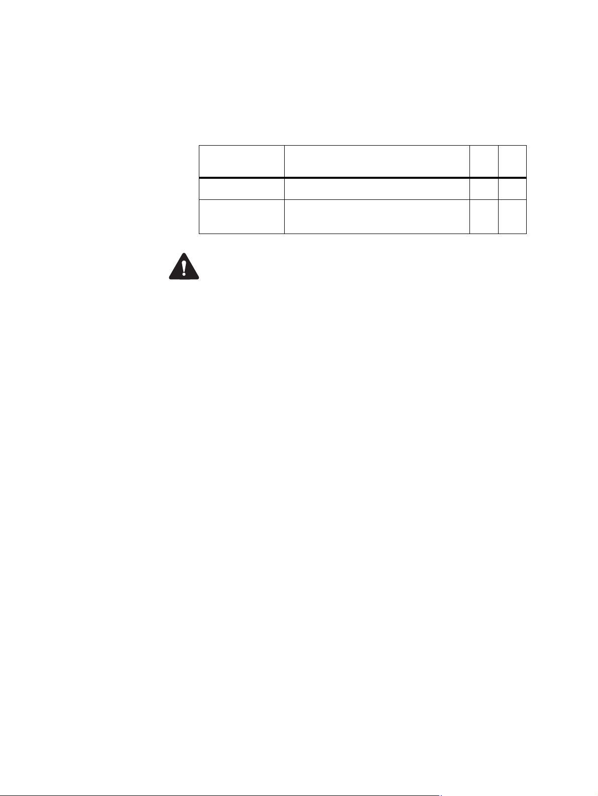
1.2 Frequency Bands and Sub-bands
Much of the circuitry in the base station is common to all frequency bands,
and is therefore covered by a single description in this manual. In some
cases the descriptions refer to specific bands or sub-bands, and these are
identified with the letters listed in the following table.
Frequency
Identification
B band B3 = 148MHz to 174 MHz x
H band H3 = 470MHz to 520 MHz
Frequency Band and Sub-band 40 W 50 W
✓
H5 = 400MHz to 470MHz
✓
Warning B3 and H5 bands are compliant with P25/AS-IP operation.
H3 band is not compliant with P25/AS-IP operation.
✓
x
x
TB7300 Installation and Operation Manual Description 11
© Tait International Limited November 2019
Page 12

1.3 Software Application Details
1.3.1 P25/AS-IP
With the P25/AS-IP software application, the TB7300 is interoperable with
TB9400 base stations, and therefore operates in P25 conventional networks
and analog conventional networks. It operates as a stand-alone repeater/
base station, or as part of a channel group, providing receiver voting and
simulcast transmission. All air interfaces and system types support
simulcast operation.
In a P25 conventional network, the TB7300 operates as a single or wide
area conventional repeater, with receiver voting and optional simulcast.
Dispatch connection is via three distinct interfaces:
■ P25 standard DFSI connection (up to three connections simultaneously)
■ Analog line
■ Tait P25 Console Gateway, supporting conversion between P25 and
analog consoles with MDC1200 signaling
In an analog conventional network, the base station can operate as a
repeater with CTCSS
1
or DCS subaudible signaling.
The base station can also operate as part of an analog conventional
simulcast network and is fully IP-connected. The base station also features
an internally integrated voter, and therefore requires no external voter.
For more information on these applications, refer to the Help and
appropriate Tait System Manual.
1. Private Line (PL).
12 Description TB7300 Installation and Operation Manual
© Tait International Limited November 2019
Page 13

1.3.2 DMR/MPT
The TB7300 is designed for operation in a Tait TN9300 DMR Tier 2
conventional radio network, a Tait TN9300 DMR Tier 3 trunked radio
network, an MPT-IP network, or as an analog conventional repeater.
In a DMR Tier 2 conventional network, the TB7300 can operate as a standalone repeater, or as a member of a multi-site system (under the supervision
of a DMR conventional node). Since DMR provides two logical channels
(timeslots) simultaneously for each radio frequency (physical channel),
two users can alternately access the same frequency, one in each timeslot.
Base stations on different sites can be linked together to form channel
groups. A base station can support two channel groups, one in each
timeslot.
In a DMR Tier 3 trunked network the TB7300 can operate as a control
channel or as a traffic channel. With two logical channels for each radio
frequency, a single TB7300 base station can provide two traffic channels,
two control channels, or both a traffic channel and a control channel.
In an MPT network, the TB7300 operates as a control channel or as a traffic
channel.
operation either trunked or conventional.
In analog operation it can operate as a conventional repeater with CTCSS
subaudible signaling
For more information, refer to the DMR System Manuals.
The TB7300 operates with a trunking node or in fallback
2
.
1
1. Private Line (PL).
2. Multi-site operation with voice-over-IP connection will be supported in a
later release.
TB7300 Installation and Operation Manual Description 13
© Tait International Limited November 2019
Page 14

1.4 Licences
Some operational functions of the base station are controlled by licences.
These functions will not work unless you purchase the appropriate feature
licence and enable the feature set controlled by that licence.
Regardless of which software application you have configured on the
TB7300, you can add and remove both P25/AS-IP and DMR/MPT
licenses.
Note that only licenses associated with your currently configured application will be enabled.
For more detailed information, please see the base station help.
1.4.1 Compatibility
The compatibility rules for P25/AS-IP and DMR/MPT are defined in the
following tables:
P25/AS-IP - Site Controller
Access Express6 Full System
P25 Access Trunking
P25 Express6 Trunking
Operation
Base Station
P25 Trunking Operation
✓
✓✓
✓
xx
✓✓
The base stations in a Tait DMR Tier 3 Network are controlled by a
node (DMR trunking controller). Tait sells three types of node: Full,
Express20 and Express6. Each type of node has different capabilities.
Refer to TN-2134 for more information
DMR - Controller
Full Express20 Express6
x
Standalone
Access
Full
Express20
Express6
Base Station
Access
14 Description TB7300 Installation and Operation Manual
✓✓✓✓
x
xx
xx
✓
© Tait International Limited November 2019
✓✓
✓✓
x
✓
Page 15

1.4.2 Feature Licences
The following section lists each of the available feature licences for both
P25/AS-IP and DMR/MPT.
P25/AS-IP Feature Licences
Feature Licence Description
Analog Air Interface
(TBAS041)
P25 Common Air Interface
(TBAS050)
P25 DFSI
(TBAS060)
P25 AS-IP Central Voter
(TBAS061)
P25 AS-IP IP Networking
Satellite
(TBAS071)
P25 AS-IP Simulcast
(TBAS062)
20/25 kHz Unrestricted
Wideband
(TBAS083)
a. Not available with H3 band
b. Not needed for receive-only base stations.
a
a
A base station with this license can operate as a repeater in an analog
conventional network.
Allows a base station to transmit and receive P25 Phase 1 C4FM digital
voice transmissions.
Allows the base station to integrate with dispatch consoles supporting DFSI
(Digital Fixed Station Interface).
P25 and analog. This feature allows a base station to act as a central voter.
All system types and all air interface types. This feature allows a base
station to be part of a channel group without requiring the Central Voter
(TBAS061) license.
This feature is required in base stations that have transmitters and belong
to a P25 Phase 1 simulcast or analog simulcast network
in the central voter of a simulcast channel.
Allows a base station to be configured to operate in wideband mode on an
analog channel, which provides a maximum deviation of 5KHz, and a
25KHz channel spacing.
b
. It is also required
TB7300 Installation and Operation Manual Description 15
© Tait International Limited November 2019
Page 16

DMR/MPT Feature Licences
Feature Licence Description
Analog Air Interface
(TBAS301 - Default License)
DMR Conventional
(TBAS304)
DMR Trunking Access
(TBAS303)
DMR Trunking Express6
(TBAS302)
DMR Trunking Express20
TBAS305
A base station with this license can operate as an MPT transceiver or an
analog conventional repeater.
A base station with this license can operate in a Tait DMR Tier 2
conventional network. It can also operate as a stand-alone repeater, or
as a member of a multi-site system (under the supervision of a DMR
conventional node).
A base station with this license can accept connections only from an
Access standalone node. This license entitles a standalone node to
control a single site of up to four physical channels.
A base station with this license can accept connections from any Express
node/standalone node or Access standalone node. In single-site trunking
and fallback modes, this license entitles a standalone node to control a
single site of up to 6 physical channels.
A base station with this license can accept connections from:
■ An Express20 node
■ An Express6 node
■ A Standalone node
■ A Standalone Access node
A base station with both a DMR Conventional license and a valid DMR
trunking license (such as Express or Access) can be configured to
operate in either mode. This enables a DMR Tier 2 base station to be
reconfigured and re-used in a DMR Tier 3 trunked network.
DMR Trunking Full
(TBAS300)
DMR Central Voter
(TBAS306)
DMR IP Networking Satellite
(TBAS307)
a. The base station itself can act as a DMR trunking controller, but with limited functionality. The base station is then said to be
a standalone node.
A base station with this license can accept connections from any node/
standalone node
This feature allows a base station to act as a DMR central voter.
This feature allows a DMR base station to be part of a channel group.
a
.
Licences are not lost or changed under software upgrades, downgrades, and changes of system
type. Older software may not display all licences.
16 Description TB7300 Installation and Operation Manual
© Tait International Limited November 2019
Page 17

License Name Air Interface System Type
TBAS041 Analog Air Interface Analog Conventional
TBAS050 P25 Common Air Interface P25 Phase 1 Conventional
TBAS060 Digital Fixed Station Interface Analog & P25 Phase 1 Conventional
TBAS061 P25 AS-IP Central Voter Analog & P25 Phase 1 Conventional
TBAS071 P25 AS-IP IP Networking
Satellite
TBAS062 P25 AS-IP Simulcast Analog & P25 Phase 1 Conventional
TBAS301 Analog Air Interface Analog Conventional/MPT Trunked
TBAS304 DMR Conventional DMR Conventional
TBAS303 DMR Trunking Access DMR Trunked
TBAS302 DMR Trunking Express6 DMR Trunked
TBAS305 DMR Trunking Express20 DMR Trunked
TBAS300 DMR Trunking Full DMR Trunked
TBAS306 DMR Central Voter DMR Trunked/Conventional
TBAS307 DMR IP Networking Satellite DMR Trunked/Conventional
Analog & P25 Phase 1 Conventional
TB7300 Installation and Operation Manual Description 17
© Tait International Limited November 2019
Page 18
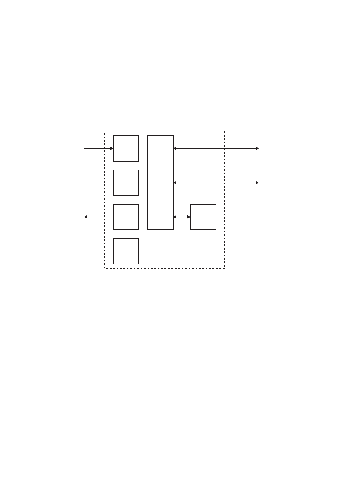
1.5 Theory of Operation
The RF input is fed directly to the receiver board, while the RF output is
via the exciter and PA boards. The control board also receives signals from,
and sends signals to, the system interface, the Ethernet interface, and the
front interface (see Figure 1.1).
The Ethernet interface carries voice over IP and also allows maintainer
access via a web browser.
Figure 1.1 Base station high-level diagram
RF Input
RF Output
System Input
Receiver
Board
Exciter
Board
PA
Board
Supply
Interface
Board
Control
Board
Front
Interface
and Output
Ethernet Interface
to Network
The control board carries out signal processing and has overall control of
the base station.
The control board converts information between analog and digital and
controls the maintainer’s access via the Ethernet interface. It performs the
air interface signal processing for digital DMR and P25 operation, gives the
base station an identity as a network element, and provides the physical
connections for the Ethernet and system interfaces.
18 Description TB7300 Installation and Operation Manual
© Tait International Limited November 2019
Page 19
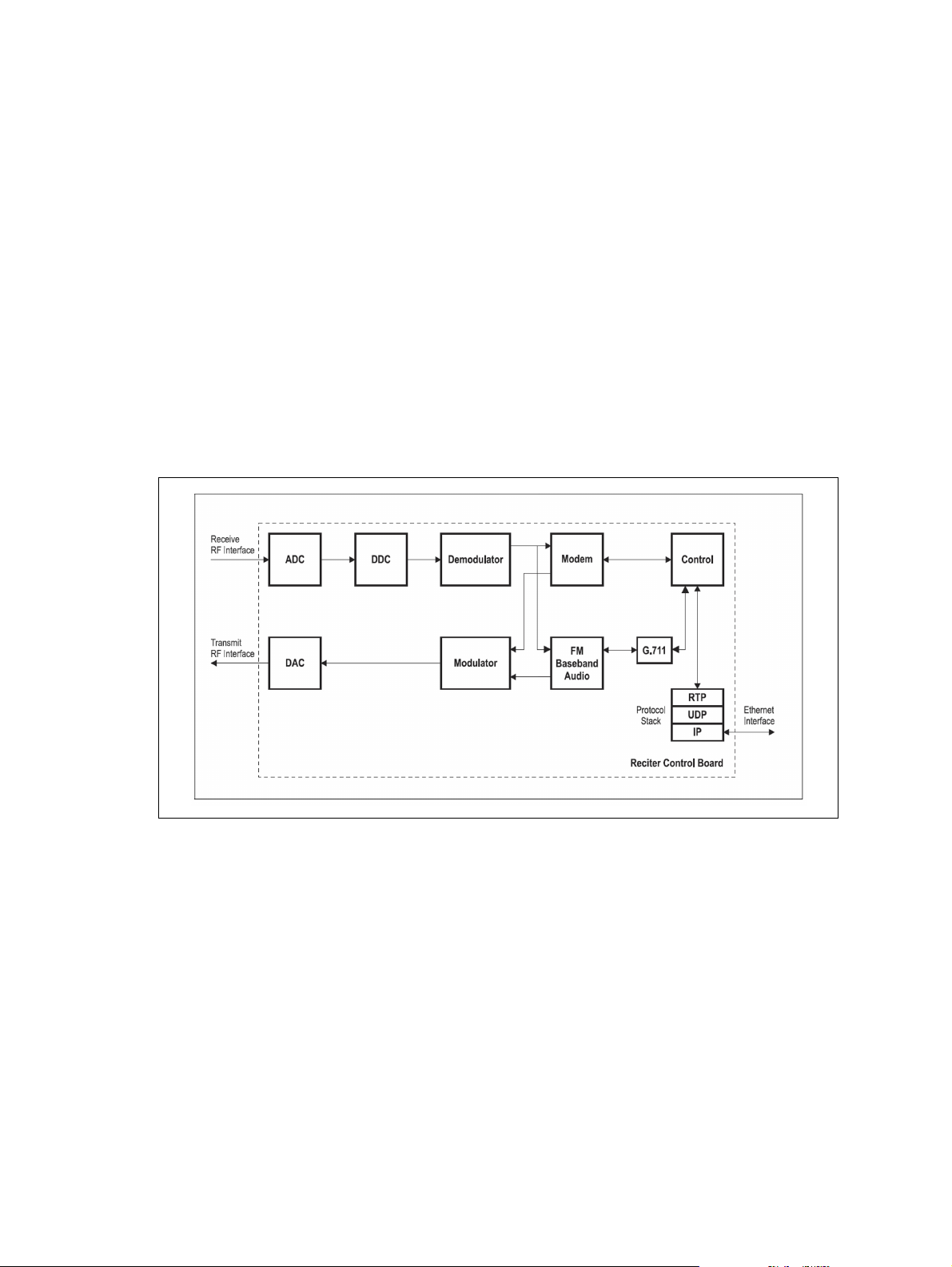
1.5.1 Signal Paths
The following figures provide an overview of signal paths within the
control boards for both software applications:
Digital P25 signals from the receive RF interface pass through the digital
receiver and P25 modem to the control software in the control processor.
The control software passes the signal through the Ethernet interface to the
site controller, to the console gateway (conventional networks), or for a
satellite, to the central voter in a simulcast system.
Input to the Ethernet interface can be from the site controller, from the
console gateway (conventional networks), or from the central voter in a
simulcast system. These inputs are processed by the control processor and
passed through the P25 modem to the transmitter. If the base station is itself
a central voter, this input can also be a received signal, which is voted on
and sent back through the Ethernet interface to the site controller.
Figure 1.2 Control board signal paths
Input to the Ethernet interface is from the node controller. This input is
processed by the RISC and passed through the DMR modem to the
transmitter.
Analog FM signals from the receive RF interface pass through the digital
receiver and are converted to G.711 before being modulated and
retransmitted.
TB7300 Installation and Operation Manual Description 19
© Tait International Limited November 2019
Page 20

1.5.2 Online and Offline Modes
The base station normally operates in Online mode, but you can put it into
Offline mode via its web interface.
Online Mode In Online mode, the base station is in service and performs its normal
functions of transmitting and receiving radio signals.
Offline Mode Offline mode allows a maintenance engineer to carry out tasks that can not
be done while the base station is in service, such as activating firmware or
running diagnostic tests.
1.5.3 Power Supply
The supply interface board accepts a nominal 13.8VDC input. The supply
interface is fused at 15A.
1.5.4 Front Panel Fans
The base station is equipped with three fans. Two fans are for the receiver,
exciter and control boards, and the third is for the PA. Front panel fans do
not operate continuously, but are switched on and off as needed. The fans
can also be temporarily enabled for test purposes via the web interface.
When the base station is powered up, the fans turn on until the main
software fully boots.
Configuring Fan
Control
The operation of the PA fans are configurable via the web interface; you
can specify the threshold temperature at which the fan will turn on, and set
the fan to operate only when the PA is transmitting.
Notice The TB7300 base station fans can’t be monitored remotely.
Malfunctioning fans may activate the PA and reciter temperature
alarms, depending on the ambient temperature and duty cycle of the
transmitter.
20 Description TB7300 Installation and Operation Manual
© Tait International Limited November 2019
Page 21

2 General Safety and Regulatory
Information
This chapter provides general information on safety precautions for
operating the base station.
2.1 Personal Safety
2.1.1 Explosive Environments
Warning
caps or in an explosive atmosphere. Operating the equipment in
these environments is a major safety hazard.
2.1.2 High Temperatures
Take care when handling a base station that has been recently operated.
Under extreme operating conditions (+140°F [+60°C] ambient air
temperature) or high duty cycles, the external surfaces of the base station
can reach temperatures of up to +176°F (+80°C).
2.1.3 LED Safety (EN60825-1)
This equipment contains Class 1 LED Products.
Do not operate the equipment near electrical blasting
TB7300 Installation and Operation Manual General Safety and Regulatory Information 21 © Tait International Limited November 2019
Page 22

2.1.4 Proximity to RF Transmissions / A proximité des émissions RF
To comply with the RF Field Limits for Devices Used by the General
a
Public for (Uncontrolled Environment)
, a safe separation distance of at
least 12 feet (3.6 metres) from the antenna system should be maintained.
This figure is calculated for a typical installation, employing one 50W
base station transmitter. Other configurations, including installations at
multi-transmitter sites, must be installed so that they comply with the
relevant RF exposure standards.
a. Reference Standards
Health Canada’s Safety Code 6: Limits of Human Exposure to
Radiofrequency Electromagnetic Energy in the Frequency Range from
3kHz to 300GHz
USA Federal Communications Commission OET bulletin 65
(47CFR 1.1310)
IEEE C95.1 2005: Standard for Safety Levels with Respect to Human
Exposure to Radio Frequency Electromagnetic Fields, 3kHz to
300GHz
Pour respecter les limites imposées au champ RF au niveau des
équipements utilisés par le grand public (environnement non contrôlé)
a
une distance de séparation de sécurité d’au moins 3.6 mètres du bloc
d’antenne devrait être observée.
,
Ce nombre est calculé pour une installation typique, ayant un émetteur de
station de base de 50W. D’autres configurations, incluant les installations
ayant des sites de plusieurs émetteurs, doivent être installées de façon à se
conformer aux normes pertinentes des expositions RF.
a. Normes de référence
Code de sécurité 6 de Santé Canada: Limites d'exposition humaine à l’énergie
électromagnétique radioélectrique dans la gamme de
fréquences de 3kHz à 300GHz
Commission fédérale des communications (FCC) des Etats Unis d’Amérique bulletin OET numéro 65 (47CFR 1.1310)
IEEE C95.1 2005: Norme pour les niveaux de sécurité compatibles avec l'exposi-
tion des personnes aux champs électromagnétiques de
radiofréquence 3kHz à 300GHz
22 General Safety and Regulatory Information TB7300 Installation and Operation Manual
© Tait International Limited November 2019
Page 23
2.2 Equipment Safety
2.2.1 Installation and Servicing Personnel
The equipment should be installed and serviced only by qualified
personnel.
2.2.2 Preventing Damage to the PA
The base station has been designed to operate safely under a wide range of
antenna loading conditions. Transmitting into a low VSWR will maximize
the power delivered to the antenna.
Notice Do not remove the load from the TB7300 while it is transmitting.
Load transients (switching or removing the load) can damage the PA output
stage. See “Connecting RF” on page 63 for recommendations.
2.2.3 ESD Precautions
Notice This equipment contains devices which are susceptible to
damage from static charges. You must handle these devices carefully
and according to the procedures described in the manufacturers’ data
books.
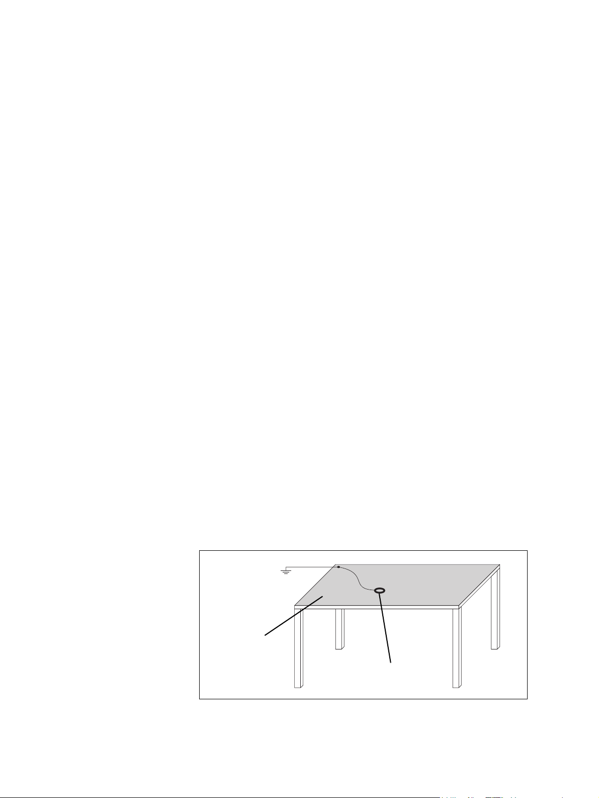
We recommend you purchase an antistatic bench kit from a reputable
manufacturer and install and test it according to the manufacturer’s
instructions. Figure 2.1 shows a typical antistatic bench set-up.
You can obtain further information on antistatic precautions and the
dangers of electrostatic discharge (ESD) from standards such as ANSI/
ESD S20.20-1999 or BS EN 100015-4 1994.
Figure 2.1 Typical antistatic bench set-up
common point ground
(building ground or
mains ground)
dissipative rubber
bench mat
conductive wrist strap
TB7300 Installation and Operation Manual General Safety and Regulatory Information 23
© Tait International Limited November 2019
Page 24

2.3 Environmental Conditions
2.3.1 Operating Temperature Range
The operating temperature range of the equipment is –30°C to +60°C
(–22°F to +140°F) ambient temperature. Ambient temperature is defined
as the temperature of the air at the intake to the cooling fans.
2.3.2 Humidity
The humidity should not exceed 95% relative humidity through the
specified operating temperature range.
2.3.3 Dust and Dirt
For uncontrolled environments, the level of airborne particulates must not
exceed 100µg/m
3
.
2.4 Regulatory Information
2.4.1 Distress Frequencies
The 406 to 406.1MHz frequency range is reserved worldwide for use by
Distress Beacons. DO NOT program transmitters to operate in this
frequency range.
2.4.2 Compliance Standards
This equipment has been tested and approved to various national and
international standards. Refer to the latest issue of the Specifications
Manual for a complete list of these standards (MBD-00002-11).
2.4.3 Unauthorized Modifications
Any modifications you make to this equipment not authorized by Tait may
invalidate your compliance authority’s approval to operate the equipment.
The manufacturer is not responsible for any radio or TV interference
caused by unauthorized modifications to this equipment. Such
modifications could void the user’s authority to operate the equipment.
24 General Safety and Regulatory Information TB7300 Installation and Operation Manual
© Tait International Limited November 2019
Page 25

2.4.4 Health, Safety and Electromagnetic Compatibility in Europe
In the European Community, radio and telecommunications equipment is
regulated by Directive 2014/53/EU. The requirements of this directive
include protection of health and safety of users, as well as electromagnetic
compatibility.
Intended Purpose
of Product
Declaration of
Conformity
This product is a radio transceiver. It is intended for radio communications
in the Private Mobile Radio (PMR) or Public Access Mobile Radio
(PAMR) services, to be used in all member states of the European Union
(EU) and states within the European Economic Area (EEA). This product
can be programmed to transmit on frequencies that are not harmonised
throughout the EU/EEA, and will require a license to operate in each
member state.
You can download the formal Declaration of Conformity from
www.taitradio.com/eudoc.
2.5 Device and Network Security
If this radio network equipment is used for mission-critical applications, it
is important to be able to ensure security and continuity of operation. For
IP-network-connected equipment, it is also important to ensure that this
equipment is not a means of compromising other equipment in the network.
All network elements should be physically secured, where possible. This
includes the use of locked cabinets and locked rooms. Seals on connectors
can also provide a visual indication of unauthorized tampering.
Tait recommends that all network and audio connectors should be sealed
with a stick-on type of seal. The seal should reveal if any of the connectors
have been unplugged, or if any unauthorized equipment has been plugged
in.
The seals should be difficult to remove without breaking, and should bridge
between the cable and equipment side (plug and socket) of the connection.
Seals should cover any unused network or audio sockets. This includes the
Ethernet connector on any adaptor front panels, any spare switch ports, and
the console port on the router and switch.
The seals should be difficult to reproduce. A sticker initialed or signed by
the technician should satisfy this.
Seals must be replaced if they need to be disturbed during maintenance.
TB7300 Installation and Operation Manual General Safety and Regulatory Information 25
© Tait International Limited November 2019
Page 26
3 Operation
3.1 Front Panel LEDs
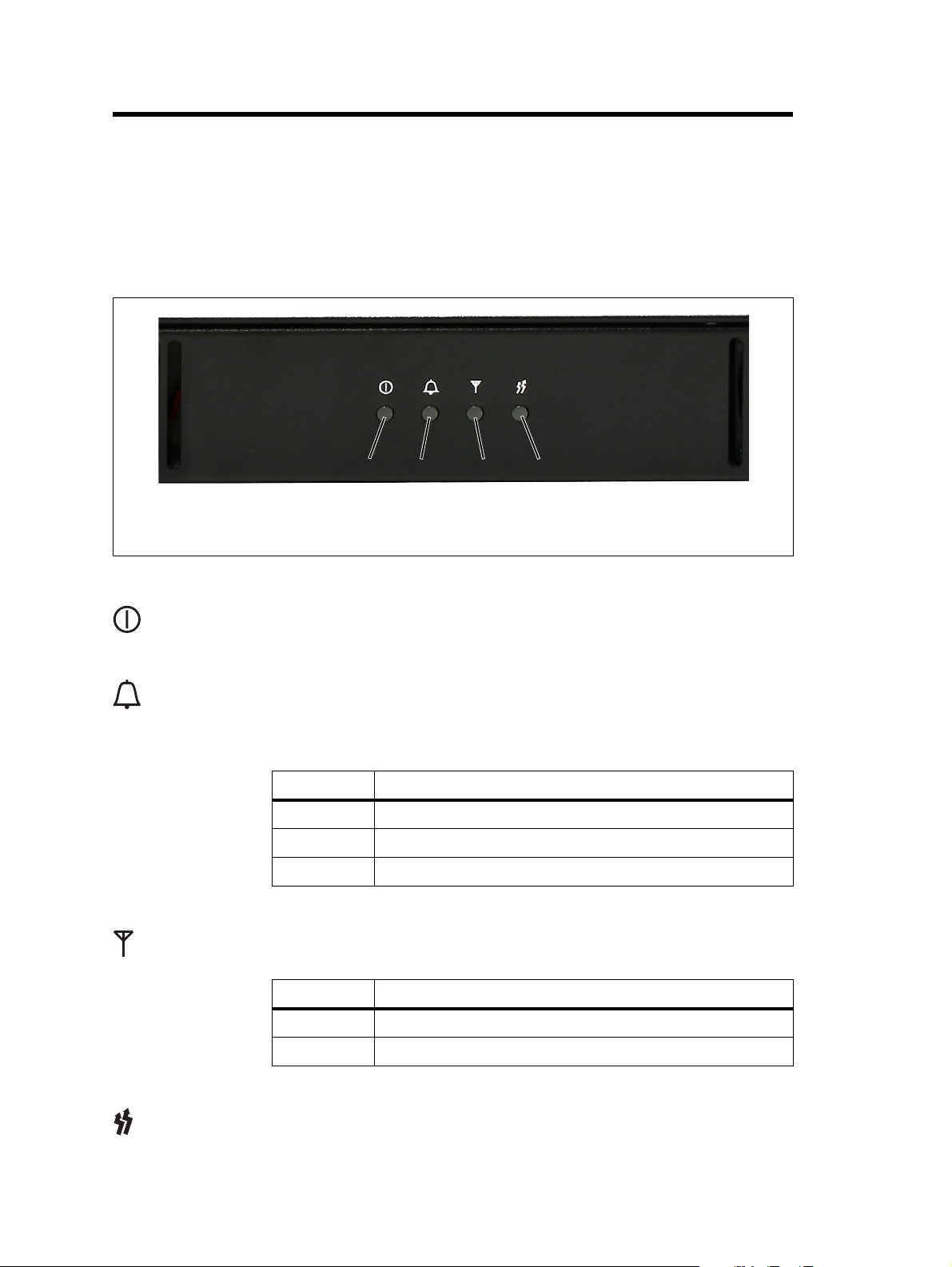
The indicator LEDs on the front panel are shown in Figure 3.1 below.
Figure 3.1 LEDs on the front panel
b
power LED
b
alarm LED
c
Power LED The green power LED is lit when power is supplied to the base station.
d
Alarm LED The red alarm LED flashes when an alarm has been generated by any of the
e
Receive LED The amber receive LED indicates whether the base station is receiving a
f
base station modules. It will continue to flash until the alarm is canceled or
the fault is fixed. Only alarms enabled using the web interface cause this
LED to flash.
LED Description
Flashing One or more faults are present.
On (steady) A base station is in Offline mode, and no faults are present.
Off A base station is in Online mode, and no faults are present.
valid RF signal on one or both logical channels.
c
d
receive LED
d
transmit LED
e
e
LED Description
On (steady) A base station is receiving a valid RF signal.
Off A base station is not receiving a valid RF signal.
Transmit LED The amber transmit LED is lit while the transmitter is transmitting.
g
26 Operation TB7300 Installation and Operation Manual
© Tait International Limited November 2019
Page 27

3.2 Rear Panel LEDs
3.2.1 Ethernet Connector LEDs
The ethernet indicator LEDs at the rear of the TB7300 are shown in
Figure 3.2 below.
Figure 3.2 Ethernet indicator LEDs
c
10Base-T Ethernet Connector LED (green)
b
10Base-T Ethernet
Connector LED
(green)
100Base-T Ethernet
Connector LED
(amber)
b c
The green ethernet connector LED will flash green if the connection is
running at 10 Mbits/s
The amber ethernet connector LED will flash amber if the connection is
running at 100 Mbits/s
b
100Base-T Ethernet Connector LED (amber)
c
TB7300 Installation and Operation Manual Operation 27
© Tait International Limited November 2019
Page 28

4 Connecting to the Base Station
The web browser on your PC provides a window into the TB7300 base
station. Use it to connect to the base station so that you can monitor,
configure, diagnose, and calibrate it (if required).
This section describes the following:
■ Connecting to the base station, including initially setting things up.
■ Working with base station web pages.
■ Carrying out basic tasks.
This section provides an overview of some aspects of the web interface.
Refer to the Help for detailed instructions.
4.1 PC Recommendations
We recommend the following PC hardware and software for connecting to
a TB7300 base station:
■ SVGA Monitor (1024 x 768 minimum).
■ Network connection.
■ The base station works with recent versions of most modern browsers.
Notice Refer to the Release Notes for more information on currently
supported browsers.
28 Connecting to the Base Station TB7300 Installation and Operation Manual
© Tait International Limited November 2019
Page 29

4.2 Connecting Your PC to the Base Station
You connect to a base station using your web browser. Using multiple
browser windows or tabs, you can view more than one base station and
more than one page of any base station at once. Base stations have a webbased interface that provides the pages you view. Up to ten users may be
logged in to a base station at once.
When loading the web user interface with Internet Explorer, the web
page may go blank. To fix this, refresh the page with the ‘F5’ key.
The base station has three different user access levels: Administrator,
Maintainer, and Monitor. Passwords can be defined for each level. This is
done using the base station’s web interface (Tools > Settings > Local users).
Refer to the Help for more information on setting user access levels.
Connections to the base station can be authenticated by a remote
(i.e. centralized) service. Refer to the Help and “Setting Up
Authentication” on page 32 for more information.
4.2.1 Logging In
1. Enter the base station’s IP address into your browser using a secure
2. A security warning appears when you connect for the first time.
3. The log in screen appears.
4. Enter your user name and password. When connecting for the first
connection ( http
To find out the base station’s IP address, refer to “Finding a Lost or
Forgotten IP Address” on page 32.
Proceed anyway (refer to “Security Certificates” on page 30).
time, enter the user name “admin” and password “tbc_admin”.
s://). The default factory IP address is 192.168.1.2.
5. Click Log In.
Notice After logging in we recommend that you change the password and username for your own security (refer to “Working with the
Web Interface” on page 33). Make sure that you store your passwords
TB7300 Installation and Operation Manual Connecting to the Base Station 29
© Tait International Limited November 2019
Page 30

and usernames securely and do not lose them. They may be needed by
Tait support personnel if assistance is required. Tait cannot retrieve
forgotten passwords.
4.2.2 Setting the IP Address
Before the base station is installed on site, you need to provide it with its
proper IP address. Make sure that you do not lose this address.
1. Select Identity > Identity > Network.
2. Enter the required details in the Change network identity area and
click Save.
When a user saves or changes the IP address of an online base station,
the base station will sometimes reset. Tait recommends that all configuration changes are made after taking the base station offline.
4.2.3 Security Certificates
You can upload your own security certificates to the base station (Tools >
Settings > Web certificate). If you have installed and configured the
appropriate Certification Authority software, you can issue security
certificates for all base stations. After uploading the certificates to the base
stations, you can configure all maintainers’ web browsers to accept
security certificates from your own Certification Authority.
Before you have uploaded a security certificate to the base station, it
will raise a security warning when your browser connects to it for the
first time. The base station creates a self-signed certificate when the
firmware is installed. Your browser raises a security warning because
the security certificate was not issued by a trusted Certification Authority. The browser will have an option to let you override or bypass the
security warning.
4.2.4 Local Connection to a Base Station
Using a computer onsite normally requires the computer have an IP address
that is compatible with the sub-netting and routing used by the
communications network. Additionally, you may need to connect to a
reciter after removing it from service.
In either case, you may have to change your computer IP address
configuration.
To connect the base station to your computer, ensure that your computer is
part of the same subnet as the base station, or has a route to it. Refer to your
operating system provider's Help for further information.
30 Connecting to the Base Station TB7300 Installation and Operation Manual
© Tait International Limited November 2019
Page 31

Base stations leave the factory with default IP address: 192.168.1.2, Subnet
mask: 255.255.255.0. If your base station will still not connect to your PC,
contact your local Tait dealer.
You may need to temporarily disconnect a networked PC from its LAN in
order to establish a direct connection with the base station. A physical
connection is needed as well as an alternate or temporary IP address and
subnet mask.
4.2.5 Troubleshooting Connection Problems
If the attempt to connect to a base station failed, consider these possible
causes.
1. Your PC is part of your organization’s LAN and does not belong to
the same subnet as the base station. Give the PC a suitable IP address
and subnet mask as described in “Local Connection to a Base Sta-
tion” on page 30.
2. You are attempting to connect to the wrong IP address. Check that
the IP address is correct.
3. The link to the base station is down. Use ping to check.
4. A connection error may occur if your PC is using the organisation’s
web proxy, but the base station doesn’t have a valid gateway address
allowing it to send responses back to that proxy. Users should ensure
that all network parameters are correct (IP address, network mask
and gateway address). You may have to bypass the proxy in your
organization’s LAN to access the radio communications network.
Ask your system administrator to give you access.
5. JavaScript may be disabled in your browser. If JavaScript is
disabled, your browser will be unable to connect to the base station.
Note that modern browsers normally have JavaScript enabled by
default.
TB7300 Installation and Operation Manual Connecting to the Base Station 31
© Tait International Limited November 2019
Page 32

4.2.6 Finding a Lost or Forgotten IP Address
Use the following procedure if an IP address has been lost or forgotten.
1. Connect your PC to the serial port on the back of the base station.
2. Run a program such as HyperTerminal, Teraterm or minicom.
3. Select the following port settings: 57600 baud, 8 data bits, no parity,
1 stop bit, no flow control.
4. Enter root as a login name, and enter the root password when
requested (the default is k1w1).
5. Type ifconfig and press Enter. The IP address is displayed on the
second line returned as “inet addr:xxx.xxx.xxx.xxx”.
4.2.7 Setting Up Authentication
Connections to the base station can be authenticated by a remote
(i.e. centralised) service (Tools > Settings > Authentication). Two remote
authentication protocols are supported: LDAP and RADIUS.
Notice Only people experienced with the AAA architecture and
authentication protocols should make changes on this page.
Moving logins to a centralized server can provide enhanced security for a
number of reasons, such as:
■ less work is required to manage password-controlled access to all base
stations in a network; you no longer need to change the password in
each base station individually.
■ previously used passwords may be excluded from re-use.
■ access can be denied after a set number of incorrect passwords is
entered.
■ passwords can be set to expire on a certain date.
■ remote access to base stations can be globally enabled and disabled as
required for technical staff during the commissioning process.
Once the centralised server logins are set up, we recommend that only one
local administrator login is left on the base station for emergency use (e.g.
when the connection to the server is lost).
The password for this emergency login should be confidential.
32 Connecting to the Base Station TB7300 Installation and Operation Manual
© Tait International Limited November 2019
Page 33

4.3 Working with the Web Interface
This section provides an overview of the web interface. Refer to the Help
for detailed instructions.
When you connect to a base station, the browser displays a page like the
following:
Accordion menu
Status bar
Alarm status. Click
System Status to go to
the Alarms screen
Model and name of
base station
Displays the
configured software
application
Click your user name
to change your
password and user
settings
Click to
disconnect
The accordion menu on the left gives you access to the various pages. Click
a top level item (such as Configure) to open up its menu. Click on a menu
item to display its page, then click on the appropriate tab on that page to
display the required information. Click the ( ) icon on a menu item to
expand the menu tree and the ( ) icon to collapse it again.
Using a browser window size smaller than 1024 x 768 may cause some
pages to display incorrectly.
TB7300 Installation and Operation Manual Connecting to the Base Station 33
© Tait International Limited November 2019
Page 34

4.3.1 Monitoring Operation
Using the monitoring pages, you can see how the base station is currently
operating.
The example screen below illustrates the base station’s network interface
under DMR/MPT conditions: (Monitor > Interfaces > DMR Network
Connections/MPT Network Connections).
An equivalent screen appears under P25/AS-IP conditions (Monitor >
Interfaces > Trunked RF).
34 Connecting to the Base Station TB7300 Installation and Operation Manual
© Tait International Limited November 2019
Page 35

4.3.2 Viewing Configuration Settings
The base station has many configuration settings that personalize it for its
particular role in the network. Some settings, such as those for alarm
thresholds (Configure > Alarms > Thresholds), always apply.
Others are channel-based so that they can be dynamically changed. To view
these, you first need to know the channel that the base station is operating
on.
To see the channel number and profiles the base station is using, go to:
■ P25/AS-IP: Monitor > Interfaces > Conventional RF.
■ DMR/MPT: Monitor > Interfaces > Analog RF or DMR RF.
TB7300 Installation and Operation Manual Connecting to the Base Station 35
© Tait International Limited November 2019
Page 36

4.3.3 Viewing the Base Station and Network Identity
Base Station
Channels
Channels can be edited from Configure > Base Station > Channels.
Select a channel and click Edit to view details of the channel. Clicking
directly on any text in a line will also open the edit screen.
Base Station
Identity
Each base station in a network has a unique base station and network
identity.
Select Identity > Identity and then Network or Base Station to view details
such as name, default channel and network addresses. Note that the Host
name field has a maximum of 63 characters, and may use the characters
a–z, 0–9, dot and hyphen. You cannot use spaces.
36 Connecting to the Base Station TB7300 Installation and Operation Manual
© Tait International Limited November 2019
Page 37

TB7300 Installation and Operation Manual Connecting to the Base Station 37
© Tait International Limited November 2019
Page 38

4.4 Basic Tasks
4.4.1 User Settings
Click on your user name in the top right corner of the page to change your
password. Note that this information is stored in the base station, not in
your browser.
4.4.2 Taking the Base Station Offline
You may need to take the base station offline in order to carry out
diagnostic tests or to take it out of service if a fault develops.
1. Click Mode on the status bar (or Select Tools > Tools > Base Station).
2. Under Control, select Offline. Click Offline to confirm the change.
In the Status area, the Mode display changes first to “Changing”, and
then to “Offline” ( ).
4.4.3 Troubleshooting Alarms
If the Alarm status on the status bar displays red, one or more alarms have
been triggered, and the Alarms menu automatically expands to display the
alarm(s). Click Help and navigate to the description of that alarm.
38 Connecting to the Base Station TB7300 Installation and Operation Manual
© Tait International Limited November 2019
Page 39

4.4.4 Working with Configuration Files
Channels To see all channels associated with both P25/AS-IP and DMR/MPT, go to
Configure > Base Station > Channels.
To make them easily recognizable, the licenses within this table are
prefixed with their specific software application (P25/AS-IP or DMR/
MPT).
If you attempt to go online with a channel that is invalid for the software
application you are currently using, an alarm will activate (Monitor >
Alarms). The alarm will warn you that the channel you are attempting
to use will not function.
TB7300 Installation and Operation Manual Connecting to the Base Station 39
© Tait International Limited November 2019
Page 40

Managing
Configuration Files
Transferring Files
Specific software application configurations can be transferred between
base stations without overwriting identity information.
Configuration
It is important to note that configuration items such as the ‘Network Access
Code (NAC)’, (air-interface specific to the P25 channel) may not be visible
on the web user interface when running its software application equivalent.
However, its configuration is still preserved in the database.
Channels specific to analog, P25, DMR or MPT operation may not be
usable by their equivalent application, but they remain in the channel
table and can be edited if required.
At any time, you can save the current configuration settings as a file
(Tools > Files > Configuration > Backup configuration). This is stored in
the base station, but we recommend that you download it and store it on
your computer as an off-site backup. The base station identity and network
identity are not saved as part of the configuration file.
The following parameters are not restored on a base station when a
configuration is restored:
■ Keypad enabled
■ Trunking capability
■ Trunking control channel priority
■ Host name
■ Default channel
■ Operating mode
■ Front panel text lines 1 through 4
■ IP address
■ Subnet mask
■ Gateway address
■ Link speed
■ SSH enable
You may want to develop a master configuration and upload it to all base
stations in the network. The master configuration can contain all the
different channel configurations and can be common to all base stations.
The base station identity selects the default channel.
Base stations are shipped with a set of factory default configurations
featuring examples of channel setups for analog FM, P25, DMR and
MPT. These configurations provide a safe set of values.
40 Connecting to the Base Station TB7300 Installation and Operation Manual
© Tait International Limited November 2019
Page 41

Tait recommends that you download these configurations and store
them on your PC as a backup before altering and saving any of your own
configuration settings.
You can also generate a report containing all the base station’s
configuration settings relevant to the current application software (Tools >
Files > Configuration > Configuration report), which can be saved as a text
file. We recommend that you do this when the base station is
commissioned. This report can be useful later if there is a problem with the
base station. Comparing the original report with the later one may highlight
changes in configuration that are causing a problem.
4.4.5 Single or channel group base stations
Base stations can operate singly, or as part of a simulcast or voted channel
group. Channel group operation is enabled in the channel group profile:
(Configure > Channel Group > [name]), and the channel group that is inuse is selected in the channel table (Configure > Base Station > Channels
> [name]). To disable channel group operation, deselect the ‘enable’ checkbox in the profile referenced by the channel. For more details, see the DMR
Simulcast and Voted Channel system manual.
4.4.6 Marshaling or transmit delay
As an IP connected base station, transmitters must buffer the signal to be
transmitted so that variations in delay in the IP network do not cause the
transmitter to underrun.
Non-simulcast channels use a configurable transmit delay. The amount of
transmit delay required varies with the QoS (specifically jitter) of the IP
transmission network.
Transmitters in a simulcast channel must all begin transmitting
simultaneously, therefore the configured value of the marshaling duration
must allow for the worst case network delay, including delay variation
(jitter).
TB7300 Installation and Operation Manual Connecting to the Base Station 41
© Tait International Limited November 2019
Page 42

The table below provides a summary of where to configure transmit or
marshaling delay:
Channel type Configured value
Single base station, P25 (Phase 1) Configure > Network Interfaces > P25
Network
Single base station, AS-IP Configure > Network Interfaces > AS-IP
Network
Simulcast channel, P25 (Phase 1) Configure > Channel Group [name] >
Synchronized – network > Fixed
duration
Non-simulcast voted channel, P25
(Phase 1)
Single base station, DMR (Tier 2, Tier 3)Configure > Network Interfaces > DMR
Single base station, MPT Configure > Network Interfaces > MPT
Simulcast channel, DMR (Tier 2, Tier 3) Configure > Channel Group [name] >
Non simulcast voted channel, DMR
(Tier 2, Tier 3)
Configure > Channel Group [name] >
Unsynchronized local Tx delay
Network
Network
Synchronized – network > Fixed
duration
Configure > Channel Group [name] >
Unsynchronized local Tx delay
For more information about configuring transmit or marshaling delay,
please see the base station help.
4.4.7 Configuring Receive-Only Base Stations
To configure the base station as receive-only, the transmitter used within
the channel profiles needs to be off. To turn off the transmitter, navigate to
Configure > RF Interface > Channel Profiles.
4.4.8 Setting Up Custom Alarms
Each of the base station’s 12 digital inputs can be used to raise a custom
alarm when the input goes high or low. The Custom Alarms form
(Configure > Alarms > Custom Alarms) allows you to assign a name to
each custom alarm.
The active state of the inputs (active high vs. active low) is configured on
(Configure > Base Station > Programmable I/O)
Custom alarms are reported via the web interface and SNMP traps.
42 Connecting to the Base Station TB7300 Installation and Operation Manual
© Tait International Limited November 2019
Page 43

Custom alarms provide a warning when an external event activates a digital
input. You can rename any of the available alarms to provide a more
meaningful name, such as “Door open”.
Take care when setting the severity of alarms, including custom alarms
(Configure > Alarms > Severity). Setting an alarm’s severity to Major
will cause the node to take the base station out of service when the alarm
is raised. Refer to the Help for more information.
4.4.9 Uploading Firmware from the Base Station
To upload firmware directly from the base station, go to Tools > Firmware > Download.
4.4.10 Downloading Firmware from a Package Server
While Tait recommends uploading firmware directly from the base station,
the base station supports downloading firmware files from a package server
(web server). Base station firmware files include a freeware web server
package, Mongoose, that is set up to allow base stations to directly
download firmware files from your computer.
Notice The version of Mongoose that Tait ships has a known security
issue (CVE-2017-11567) that makes Mongoose unsuitable for use on
the public Internet. For more information, please see the base station
help.
4.4.11 Activating New Firmware
The web UI page Tools > Firmware > Activate allows you to review the
two software packages stored on the base station and activate the one that
is presently inactive.
The base station can remain online while doing upload or download,
minimizing any outage time for activation.
Two packages allows separation of the upload or download from the
activation itself. Minimizing the outage time when upgrading the firmware.
After activation, the inactive firmware allows you to quickly revert to the
previous version should you choose to.
Application Packages
TB7300 can run two distinct applications: P25/AS-IP and DMR/MPT. You
can switch between the two at any time, and run the other. However, there
are certain functions associated with each application that are only possible
TB7300 Installation and Operation Manual Connecting to the Base Station 43
© Tait International Limited November 2019
Page 44

when running that specific software. For more information, please see the
base station help.
The TB7300 can store two complete application packages in two distinct
slots, one of which is active at any time. This is useful for switching
between software applications (e.g. P25/AS-IP to DMR/MPT).
Switching Application Packages
To switch between one software application package to another, you must
first activate the software in the inactive slot. Once that software is active,
the base station will reboot and the new software will begin running.
4.4.12 Subaudible Signaling
The purpose of CTCSS and DCS signaling (PL and DPL) is to reject
transmissions from radios that do not belong on the network. It is possible
for digital signals such as DMR to cause falsing with some codes. If
possible, you should avoid the following subaudible codes, which can be
subject to false triggering from P25 or DMR signals:
Subaudible Type Code Values
CTCSS (PL) 131.8 Hz
DCS (DPL) 356
199.5 Hz
233.6 Hz
431
723
44 Connecting to the Base Station TB7300 Installation and Operation Manual
© Tait International Limited November 2019
Page 45

4.4.13 SNMP Network Management
Tait base stations provide Management Information Bases (MIBs), to allow
network management using SNMP.
The Windows MSI installer includes Tait defined MIBs (look for a folder
labeled MIBs under Tait Applications in the Windows Start menu), and
they are also published on the Tait Technical support website: http://
support.taitradio.com/home
The following table summarises the base station MIB files and indicates
with hardware and software application they apply to.
The “94Series” MIB applies to P25 and AS/IP operation for TB9400,
and TB7300 base stations.
The “93Series” MIB applies to DMR/MPT operation for TB9300 and
TB7300 base stations.
File Hardware Software Description
TAIT-COMMON-MIB.mib TB9400,
TB9300,
TB7300,
transportable
TAIT-INFRA9394SERIES-COMMONMIB.mib
TAIT-INFRA9394SERIES-TC-MIB.mib
TAIT-INFRA94SERIESTC-MIB.mib
TAIT-INFRA94SERIESMIB.mib
TAIT-INFRA94SERIESNOTIF-MIB.mib
TB9400,
TB9300,
TB7300,
transportable
TB9400,
TB9300,
TB7300,
transportable
TB9400,
TB7300,
transportable
TB9400,
TB7300,
transportable
TB9400,
TB7300,
transportable
Any Common declarations for all
Tait products.
Any Common declarations for
Tait base stations.
Any Textual conventions:
Common type definitions for
Tait base stations.
P25/AS-IP
P25/AS-IP
P25/AS-IP
P25/AS-IP
P25/AS-IP
P25/AS-IP
P25/AS-IP
P25/AS-IP
P25/AS-IP
Textual conventions: Type
definitions for P25/AS-IP
operation.
Monitored object definitions
for P25/AS-IP operation.
Trap definitions for P25/ASIP operation
TAIT-INFRA93SERIESTC-MIB.mib
TAIT-INFRA93SERIESMIB.mib
TAIT-INFRA93SERIESNOTIF-MIB.mib
TB7300 Installation and Operation Manual Connecting to the Base Station 45
© Tait International Limited November 2019
TB9300,
TB7300,
transportable
TB9300,
TB7300,
transportable
TB9300,
TB7300,
transportable
DMR/MPT
DMR/MPT
DMR/MPT
DMR/MPT
DMR/MPT
DMR/MPT
DMR/MPT
DMR/MPT
DMR/MPT
Textual conventions: Type
definitions for DMR/MPT
operation.
Monitored object definitions
for DMR/MPT operation.
Trap definitions for DMR/
MPT operation
Page 46

5 Installation
This chapter provides information on the site requirements for your
TB7300 equipment and also describes how to install the base station in a
standard 19 inch rack or cabinet.
If this is your first time installing a TB7300 base station, we recommend
that you read the entire chapter before beginning the actual installation.
5.1 Before You Begin
5.1.1 Equipment Security
The security of your base station equipment is a high priority. If the site is
not fully secure, the base station should at least be locked in a secure,
ventilated cabinet to prevent unauthorized access.
5.1.2 Grounding and Lightning Protection
Electrical Ground A threaded grounding connector is provided on the rear of the tray for
permanent connection to the site protective ground point (refer to for more
details). The minimum wire gauge for this connection is 1.35mm²/16AWG.
Lightning Ground It is extremely important for the security of the site and its equipment that
you take adequate precautions against lightning strike. Because it is outside
the scope of this manual to provide comprehensive information on this
subject, we recommend that you conform to your country’s standards
organization or regulatory body.
46 Installation TB7300 Installation and Operation Manual
© Tait International Limited November 2019
Page 47

5.1.3 Equipment Ventilation
Always ensure there is adequate ventilation around the base station (refer
to “Cabinet and Rack Ventilation” on page 47).
Notice Do not operate equipment in a sealed cabinet. The ambient
temperature must stay within the specified range. We recommend
strongly that you ensure the cooling airflow is not restricted.
Notice The cooling fans are mounted behind the front panel. To
ensure adequate airflow through the base station, do not operate it for
more than a few minutes with the fans disconnected (such as when the
base station is being serviced).
5.1.4 Ambient Temperature Sensor
The ambient temperature reading for the base station is provided by the
temperature sensor located inside the chassis.
5.1.5 Cabinet and Rack Ventilation
The cooling airflow for the subrack enters through the front panel and exits
at the rear. For optimum thermal performance, the heated air that passes
through a base station must never be allowed to re-enter the air-intakes on
the front panel. Any space at the front of the cabinet not occupied by
equipment should be covered by a blanking panel. See Figure 5.1 on
page 48.
Equipment installation should observe the following guidelines:
■ The recommended maximum number of subracks in a 38U cabinet is
twenty, as illustrated in Figure 5.1 on page 48.
■ Any space at the front of the cabinet not occupied by equipment should
be covered by a blanking panel. Refer to Figure 5.1 on page 48.
■ Subrack placement in the cabinet should include a 2U gap at the top of
the cabinet.
■ To allow enough cooling airflow through a cabinet-mounted base
station, the cabinet should allow for 50 cu.ft/min for each subrack
(0.024 cu.m/s).
■ To ensure adequate ventilation, the cabinet should have a vent at the top
with an area of approximately 23in² (150cm²) per subrack, or a similar
area of ventilation at the rear of the cabinet behind each subrack.
■ The maximum ambient temperature at the base station front panels must
not exceed +140°F (+60°C).
TB7300 Installation and Operation Manual Installation 47
© Tait International Limited November 2019
Page 48

Figure 5.1 Typical cabinet ventilation requirements
b
20cm
(8in)
side view front view
2U
top view
≥10cm
(≥ 4in)
e
c
d
c
ventilation slots
b
blanking panels
c
48 Installation TB7300 Installation and Operation Manual
airflow entry
d
airflow exit
e
© Tait International Limited November 2019
Page 49

5.2 Unpacking the Equipment
Unpacking the
Base Station
Disposal of
Packaging
The base station is packed in a strong corrugated cardboard carton with top
and bottom cushions.
1. Cut the tape securing the flaps at the top of the carton and fold them
flat against the sides.
2. Rotate the carton carefully onto its side and then onto its top,
ensuring that none of the flaps are trapped underneath.
3. Slide the carton upwards over the cushions and lift it away. Remove
the cushion from the bottom of the base station.
4. Lift the base station clear of the remaining cushion.
If you do not need to keep the packaging, we recommend that you recycle
it according to local recycling methods. The cushions are CFC- and HCFCfree and may be burnt in a suitable waste-to-energy combustion facility, or
compacted in landfill.
TB7300 Installation and Operation Manual Installation 49
© Tait International Limited November 2019
Page 50

5.3 Identifying the Equipment
You can identify the model and hardware configuration of the TB7300 by
referring to the product code printed on a label at the rear of the base
station. The meaning of each character in the product code is explained in
the table below.
This explanation of product codes is not intended to suggest that any
combination of features is necessarily available in any one product.
Consult your regional Tait office for more information regarding the
availability of specific models and options.
Product Code Description
TB7310-XXXX-XXXX-XXXX-10 DMR/MPT
Frequency Band
B3 = 148 MHz to 174MHz
H3 = 470MHz to 520MHz
H5 = 400 MHz to 470 MHz
TB7360-XXXX-XXXX-XXXX-10 P25/AS-IP
Frequency Band
B3 = 148 MHz to 174MHz
H5 = 400 MHz to 470 MHz
TB73XX-XXXX-XXXX-XXXX-10 B = 40/50 W
TB73XX-XXXX-XXXX-XXXX-10 0 = default
TB73XX-XXXX-XXXX-XXXX-10 0 = default
TB73XX-XXXX-XXXX-XXXX-10 0 = 13.8 VDC (nominal) input
TB73XX-XXXX-XXXX-XXXX-10 0 = default
TB73XX-XXXX-XXXX-XXXX-10 Feature License
00 = None [Default: Analog (TBAS301)]
AC = DMR Express SFE License with TDMA
operation (TBAS302)
AD = DMR Access SFE License with TDMA
operation (TBAS303)
AE = DMR conventional (TBAS304)
TB73XX-XXXX-XXXX-XXXX-10 10 = default
50 Installation TB7300 Installation and Operation Manual
© Tait International Limited November 2019
Page 51

5.4 Initial Setting Up
Before putting the base station into service, you may want to carry out
some basic functional testing, configuration, and tuning (if required). This
section provides an overview of these procedures:
■ checking that the base station powers up correctly
■ checking the basic functionality of the base station by using the tests
available in the web interface
■ customizing the configuration for the intended installation and
verifying that the configuration is correct
■ changing the root password
■ tuning the base station, if required
5.4.1 Confirming Operation
Notice The RF output must be connected to a suitable attenuator or
dummy load. Do not remove the load while the PA is transmitting as
this may damage the PA output stage.
Applying Power 1. Apply power to the TB7300.
2. Check that the base station powers up correctly:
All LEDs turn on initially, then the transmit and receive LEDs turn
off, leaving the green power LED on, and the red alarm LED flashing. The alarm LED will turn off when the base station has finished
its start-up sequence.
Functional Tests The following table provides an overview of the tests available using the
web interface. Refer to the base station Help for full details of these tests.
Test Notes Menu
receiver operation requires a suitable RF source Diagnose > RF Interface > Receiver
transmitter operation requires connection to the
network
ping checks the IP connection to
another device with an IP address
NTP query checks if the NTP-based time
synchronization is working
Diagnose > RF Interface > Transmitter
Diagnose > Connection > Network
TB7300 Installation and Operation Manual Installation 51
© Tait International Limited November 2019
Page 52

5.4.2 Working with Configurations
The Web UI page under Tools > Files > Configuration allows you to
manage your base station configuration. The base station can store up to 10
configurations internally.
New configurations are created on the base station and uploaded to your
PC. They can also be transferred from one base station to another, and can
be transferred from one software application to another.
It is important to note that not all configuration values apply to both
software applications e.g. DMR/MPT has colour codes, and P25 has NAC
values.
When working with base station configurations, you can do the following:
■ Back up a configuration: Stores a snapshot of the base station’s current
configuration.
Tait recommends creating a back-up of the current configuration before
making significant configuration changes. A backed up configuration is
added to the list of stored configurations on the base station.
■ Upload a configuration: Copies a configuration from your computer to
the base station. You can develop a master configuration and upload it
to all the base stations in the network. Uploading a configuration adds
to the set of stored configurations but does not make that configuration
active.
52 Installation TB7300 Installation and Operation Manual
© Tait International Limited November 2019
Page 53

When transferring configuration values between base stations, or from
one software application to another, all configuration values are preserved.
To copy configurations between base stations, you can download the
configuration file from the source base station, then upload and restore
this to a new base station.
■ Restore a configuration: Makes the selected configuration active.
■ Download a configuration: Copies the selected configuration to your
computer so that you can store it. To download a configuration file,
click on the name of the saved configuration in the list of saved
configurations.
■ Create a human readable configuration report: Download and save a
text report of the base station’s configuration settings. You can use it to
capture, view, review, and compare configurations.
It is safe to restore configurations created under different base station
software versions than the one currently operating. When restoring a
configuration from an old version that doesn’t contain values defined
for all configurations parameters, any absent data values are set to
default.
The following parameters are not over-written when restoring a
configuration from a different base station:
■ Keypad enabled
■ Secure shell (SSH) console access enabled.
■ Receiver number
■ Host name
■ Default channel
■ Operating mode
■ Front panel text lines 1 through 4
■ IP address
■ Subnet mask
■ Gateway address
■ Link speed
TB7300 Installation and Operation Manual Installation 53
© Tait International Limited November 2019
Page 54

5.4.3 Customizing the Configuration
The following steps provide an overview of the process used to configure
the base station with the settings it needs. Refer to the Help for more
detailed information.
1. Log in to the base station (refer to “Connecting Your PC to the Base
Station” on page 29 for more details).
2. Select ‘Configure.’ The base station has many different settings that
can be configured before it is put into operation, such as:
■ Channel configurations
■ Alarm control and SNMP agent
■ Network interfaces
■ Quality of service
■ CWID
■ Miscellaneous items such as minimum battery voltages, fan
control, NTP and package servers.
Default
Configuration
Parameters
3. Make the changes needed in each form and click, ‘Save.’ All
changes made in the form will only be applied when the form is
saved.
Notice Before making changes, you should save the configuration to
your PC or network; this provides a baseline which can be restored to
the base station if the configuration information becomes lost or corrupted.
You should also back up the configuration before downgrading to a different software release. Note that if you downgrade and then upgrade
software, configuration values for new features will generally disable
the feature.
The base station is delivered from the factory with a saved configuration
containing factory defaults. The configuration is named something like
‘QBCS20CF_11.dat’.
The default configuration file is associated with both P25/AS-IP and DMR/
MPT and serves as a starting point for when you need to create your own
tailored configuration.
Base stations from the factory all have the same default configuration file.
As a result, some settings will not be correct for your network. Frequency
plan and alarm settings are examples.
For further information, please contact your local Tait dealer.
54 Installation TB7300 Installation and Operation Manual
© Tait International Limited November 2019
Page 55

5.4.4 Restricted Port Numbers
Certain configuration settings in the base station’s web interface require
you to enter a port number (for example, the trunking interface).
The following two ranges of port numbers are unavailable for use with the
base station:
Restricted Port Numbers Details
0 – 1023 The “well-known ports”, commonly used by other devices in a
network. Using a port number in this range could cause
compatibility problems with other devices.
12000 – 14999 Reserved for internal use in the base station. Using a port number
in this range could cause the base station to malfunction.
5.4.5 Changing the Root Password
Notice The following procedure can be carried out only if secure
shell access (SSH) is enabled. Secure shell access to the base station is
disabled by default from version 1.35 onwards. To enable SSH, select
Tools > Settings > Secure shell and click ‘Start’.
The root password to the Linux operating system of the base station is a
possible security risk. The equipment is delivered with a default password
that is well known. Knowledge of the password could be used to render the
equipment inoperable, for example, by deleting files. If you are concerned
about the security risk that this poses, change the password. If Tait provides
support services, they will likely need to know the password.
Notice If you change the password and then lose it, the equipment
must be returned to Tait. Make sure that you store the password securely
and do not lose it.
The serial port uses the same password but is unrelated to SSH.
To change the root password, follow these steps:
1. Log in from your PC to the base station using SSH client software
such as PuTTY. The username is root and the default password is
k1w1.
2. At the # prompt, enter the command passwd.
3. Follow the on-screen instructions.
4. Record the password in a secure location.
Tait networks are deployed with default weak passwords. For the sake
of security, Tait strongly recommends changing the default password
where applicable.
TB7300 Installation and Operation Manual Installation 55
© Tait International Limited November 2019
Page 56

5.4.6 Tuning the Receiver
Before the base station is installed on site, you may need to tune the
receiver front end. The receiver front end requires tuning if the receive
frequency is shifted more than 2MHz away from the previously set
frequency, or the RSSI level of the new frequency is more than 1dB lower
than the RSSI level of the previously set frequency.
The following table indicates which bands require manual tuning, and
which bands are electronically tuned:
Band Manual Electronic
B3 Band Manual
Tuni ng
B3
H3 x
H5 x
✓
x
✓
✓
This section provides instructions for tuning the B3 band reciter.
The base station receiver signal level diagnostic (Diagnose > RF Interface > Signal Level) offers the ability to verify that the configured
receiver frequency aligns with the receiver tuning.
When the frequency sweep is set to “Use calibrated noise source”, the
resulting curve represents the receiver front end response, and provides
a quick visual check of whether the receiver is optimally tuned. A well
tuned receiver should have the maximum response at the operating frequency. See the online help for more details.
The B3 receiver covers the frequency range: 148 to 174MHz
The B3 band is split into two sub-bands:
■ 148to159MHz
■ 159to174MHz
Each sub-band has its own helical filter (shown in Figure 5.2 below) which
is electronically switched in or out of circuit depending on the frequency
programmed into the base station. The bandwidth of these helical filters is
approximately ±1.5MHz.
56 Installation TB7300 Installation and Operation Manual
© Tait International Limited November 2019
Page 57

Figure 5.2 Identifying the B-band receiver front end helical filters
B3: 148 to 159MHz
B3: 159 to 174MHz
TB7300 Installation and Operation Manual Installation 57
© Tait International Limited November 2019
Page 58

To check the RSSI level and tune the receiver front end (if required), follow
these steps:
1. Place the base station on its side or upside down to allow access to
the holes on the base to tune the helical filters.
2. Log in to the TB7300 and select Monitor > Interfaces > RF Interface.
For information on connecting directly to the base station, refer to
“Local Connection to a Base Station” on page 30.
3. Feed a signal at the currently tuned receive frequency and at a level
of –80dBm into the RF input. Check that the RSSI reading on the
RF Interface page is –80dBm ±1dB.
4. Set the TB7300 to the new receive frequency.
5. Change the RF input signal to the new receive frequency at
–80dBm. Check that the RSSI reading is – 80dBm ±1dB. If it is, the
receiver front end does not require tuning. If it is not, go to the next
step.
1
6. Using the Johanson tuning tool
the new frequency (as shown in Figure 5.2) to obtain a peak RSSI
reading. This reading should be within 1dB of the reading at the
previous frequency.
Adjust the center resonator of the filter first, followed by the two
outer resonators (in any order). Each resonator should require
approximately the same amount of adjustment when tuning.
, adjust the correct helical filter for
A change in frequency of 5MHz requires approximately one turn of the
tuning slug. If tuning to a lower frequency, turn the slug clockwise; for
a higher frequency, turn the slug anti-clockwise.
7. Change the RF input signal and the receive frequency to 0.5MHz
above and below the required frequency and check that the RSSI
reading does not drop by more than 0.5dB from the reading at the
required frequency.
8. Recalibrate the RSSI at the new frequency (Calibrate > Calibrate >
RSSI).
If you wish to confirm the accuracy of the tuning procedure, carry out a
sensitivity measurement at the new frequency.
1. Included in the TBA0ST2 tool kit. Also available separately as part number 937-00013-00.
58 Installation TB7300 Installation and Operation Manual
© Tait International Limited November 2019
Page 59

5.5 Installing the Base Station on Site
5.5.1 Base Stations for Trunked Systems
When installing base stations that are part of a trunked system, it is
important to observe good site engineering rules. This is especially true
when the channels are combined into a single antenna.
If possible, the RF planner should avoid frequency plans in which the Rx
to Tx spacing is an exact multiple of the trunked channel spacing, thus
forcing Tx intermodulation products to fall outside the Rx channels.
Cables and antennas should be of high quality. Solid shield heliax cables
are best, but if braided shield cables must be used for short distances, their
braids must be silver-plated. Isolators must be used at all transmitter
outputs.
When the outputs of more than one transmitter are combined, their voltages
add, and the resulting peak envelope power is not simply the sum of their
powers, but is equal to the power of one of them multiplied by the square
of the number of sources. Cables, components, and hardware must be rated
to withstand the peak envelope power.
During the commissioning process, all transmitters should be activated
together using a diagnostic test tone, while the receiver RSSI is monitored.
There should be no discernible increase in RSSI while the transmitters are
active.
5.5.2 Equipment Required
It is beyond the manual’s scope to list everything required. However, the
following tools and equipment are specifically required for installing the
base station:
Too ls ■ Philips #2 tip screwdriver used to connect the DC power cables to the
DC power terminals
■ Pozidriv PZ3 screwdriver for the M6 screws used to secure the tray to
the cabinet in Tait factory-assembled systems
■ 8mm spanner for the M5 nut on the ground connector
You can also obtain the TBA0ST2 tool kit from your regional Tait office.
It contains the basic tools needed to install, tune, and service the base
station.
Base Station
Calibration Test
Unit & Cable
TB7300 Installation and Operation Manual Installation 59
© Tait International Limited November 2019
The Base Station Calibration Test Unit supports test and diagnosis. It is
available for order under TBA0STU. It contains a breakout box, tone
source and speaker.
Page 60

5.6 Mounting the Base Station
1. Fit the base station into the cabinet or rack and secure it firmly with
an M6 (or 0.25in if using the imperial system) screw, flat and spring
washer in each of the four main mounting holes
Figure 5.3 on page 60.
2. The base station can be wall-mounted by rotating the front mounting
brackets and fitting the optional rear brackets (TBBA03-01). When
the base station is wall-mounted ensure the airflow is from bottom to
top (front panel mounted down) or side to side.
3. For transport or in installations subject to vibration, the base station
should be supported at the rear using a transit bracket
(Tait recommends using the TBBA03-04 transit bracket).
Figure 5.3 Base station mounting points
b, as shown in
c
D
b
E
f
main mounting holes
b
base station
c
DC power connector
d
Cabling Tait recommends you route all cables to and from the base station along the
side of the cabinet so the cooling airflow is not restricted.
e
f
ground point
rack frame
Cables should be well supported so that the connectors or terminals on the
base station and on the ends of the cables do not have to support the full
weight of the cables.
Cables must be routed so that they do not restrict the air outlets at the rear
of the base station.
60 Installation TB7300 Installation and Operation Manual
© Tait International Limited November 2019
Page 61

5.6.1 Mounting and Support Kits
For TB7300 mounted and support operation, Tait offers the following kits
for order:
Item Number Item Description
TBD-SP-0002 TB7300 Wall
Mounting Kit
TBD-SP-0003 TB7300 Rear
Support Bracket Kit
5.7 Connecting the Base Station
This section provides information relevant to the task of connecting up the
various inputs and outputs of the base station.
5.7.1 Connection Overview
External connections are all located at the rear of the base station. See
Figure 5.4 below.
Figure 5.4 Base station inputs and outputs
Wall-mounting option with brackets
that attach to the rear of the chassis
Provides additional support when the
base station is mounted in a rack
e
b
ground connector
b
system interface connector
c
Ethernet interface connector
d
RF input
e
serial RS-232 connector
f
TB7300 Installation and Operation Manual Installation 61
© Tait International Limited November 2019
c
d
f
g
h
g
h
i
j
1)
i
RF output
1PPS input connector
-VDC input
+VDC input
External reference input
j
1)
Page 62

5.7.2 Connecting DC Power
The base station is designed to accept a nominal 13.8V DC, with negative
ground.
Notice Any mains power supply used to power the base station is
required to meet the isolation separation for reinforced insulation of
3000Vrms or 4242VDC.
The DC power connector at the rear of the base station is a heavy-duty M4
screw terminal connector suitable for many forms of connection.
Pin Signal Name Signal Type Notes External View
1 ground input The maximum current for
each band:
2 13.8VDC input
■ B band: 50W 9.6A
Typical
■ H band: 40W 8.1A
Typical
You must connect the DC supply from the battery to the base station via a
readily accessible disconnect device such as a fuse or DC-rated circuit
breaker with the appropriate rating, as shown in the table below.
The DC input leads should be of a suitable gauge to ensure less than 0.2V
drop at maximum load over the required length of lead. Use only flexible
copper cables.
Nominal
Supply Voltage
13.8VDC 11.8 VDC to 14.4 VDC 20 A 12AWG / 3.3mm
a. For a length of 1.5m to 2m (5ft to 6.5ft) (typical).
Input Voltage
Range
Circuit Breaker/
Fuse Rating
Recommended
Wire Gauge
a
a
Terminate the DC input leads with a suitable crimp connector for attaching
to the M4 screws of the DC power connector.
62 Installation TB7300 Installation and Operation Manual
© Tait International Limited November 2019
Page 63

5.7.3 Connecting RF
Notice Do not remove the load from the base station while it is trans-
mitting as this may damage the PA output stage. Before disconnecting
RF cables, put the base station into ‘Offline’ mode to prevent any transmissions.
The RF input to the base station is via the marked BNC connector on the
rear panel. The RF output is via the N-type connector on the rear panel
(refer to Figure 5.4 on page 61).
Cables and antennas should be of high quality. Solid shield heliax type
cables are best, but if braided shield cables must be used for short distances,
their braids must be silver-plated.
Recommendations
for Installing the
Base Station
We recommend the following installation procedures, which should protect
the PA from damage under all but the most extreme operating conditions
1. Do not connect the base station directly to the antenna. Fit an isola-
tor or duplexer between the base station and the load. Fit the isolator
as close as possible to the RF output connector on the base station.
Do not connect any switching equipment between the isolator and
the base station, unless the switch cannot operate while there is RF
present (i.e. the base station is transmitting).
2. Fit a surge suppressor to the antenna cabling where it enters the
building.
3. Inspect all cables and equipment connected to the base station for
defects.
A broken antenna or ice is unlikely to cause damage to the PA.
Explanation The circuit design of the PA protects the circuitry from high VSWR. This
makes it difficult to damage the RF power device by keying the PA into a
mismatched load, or if the load deteriorates over even a short period of time
(milliseconds).
However, it is possible to damage the device if all the following conditions
happen at the same time:
■ there is a step change in the PA load (for example, the load is removed)
■ the PA is transmitting
■ the feed line loss between the PA and the mismatch is <1dB
The effect of such conditions is variable: some devices will not be
destroyed, and some may fail after repeated load interruptions.
TB7300 Installation and Operation Manual Installation 63
© Tait International Limited November 2019
Page 64

5.7.4 Connecting an External Frequency Reference
An external reference frequency is not normally required for B band.
However, an external reference can be used when you need to maximize
the range of the base station. The external reference frequency can be
10MHz or 12.8MHz, with an input level of 300mV
stability of this reference should be better than 100 parts per billion. The
base station automatically detects the frequency of the external reference
and configures itself accordingly.
Notice An external reference is required for simulcast operation.
If an external reference is required, enable the external reference “external
reference absent” alarm (Configure > Alarms > Control).
Use a 50Ω coaxial cable (RG58 or RG223) to connect the external
reference to the base station’s external reference frequency input. You can
daisy-chain up to eight base stations using T-junctions. The maximum
overall cable length is 30m. Terminate the last connection (including single
base stations) with a 50Ω load.
to 5Vpp. The
pp
Figure 5.5 Daisy-chaining an external frequency reference input
maximum of eight base
station loads on one
frequency reference output
maximum overall cable
length is 30m
50Ω termination
64 Installation TB7300 Installation and Operation Manual
© Tait International Limited November 2019
Page 65

5.7.5 Connecting a 1PPS Source
A 1PPS signal is required for simulcast base stations. Use a 50Ω coaxial
cable (RG58 or RG223) to connect the source to the base station’s 1PPS
input. You can daisy-chain up to eight base stations using T-junctions. We
recommend that the cable length between the first and last load is kept to a
minimum. This will reduce any propagation variation between base
stations. The maximum overall cable length is 30m. Terminate the last
connection with a 50Ω resistor, otherwise reflections of the 1PPS pulse
may occur.
Notice If 1PPS is used, then 1PPS and NTP must both be derived
from the same time base. Normally this will be a GPS disciplined
source.
Figure 5.6 Daisy-chaining a 1PPS input
The longest length of cable must be
between the source and the first base
station
Maximum of eight base station
loads on one 1PPS output
50Ω termination
Use short lengths of cable
between each base station
TB7300 Installation and Operation Manual Installation 65
© Tait International Limited November 2019
Page 66

5.7.6 Ethernet Connection
The RJ-45 socket on the reciter’s rear panel provides the 10 BASE-T or
100 BASE-T Ethernet connection to the other devices in the network. Use
a Cat-5 cable to connect this socket to the Tait Network via a router or
switch.
The Web UI allows you to set the Ethernet port speed auto-negotiation to
10/100 Mbit/s or to negotiate a maximum 10 Mbit/s. Tait recommends that
you keep the port speed at the factory default setting of 10 Mbit/s. The
reciter hardware and software are scaled to meet the performance
requirements of processing multiple voice streams along with supervisory
control and management communications. 10 Mbit/s is ample for those
requirements. The 10/100 Mbit/s setting is provided for compatibility
reasons, but it is possible under high traffic conditions at 100 Mbit/s for
traffic arriving at the reciter at the full rate within a small timing window
to overflow internal buffers and therefore suffer packet loss. If you set the
port speed to 100 Mbit/s and observe QoS lost packet alarms, then review
your Ethernet port speed settings.
With the port speed at 10 Mbit/s it is particularly important to set the voice
QoS on the reciter port of your site router or switch to a strict priority queue
policy - which is the same policy that you should also be setting for your
site link ports. The default QoS settings restrict the voice bandwidth to 1/
25th of the port speed which is smaller than the required bandwidth for
typical systems at 10 Mbit/s.
If necessary, refer to “Ethernet Connector” on page 71 for a list of Ethernet
connection pin allocations.
66 Installation TB7300 Installation and Operation Manual
© Tait International Limited November 2019
Page 67

5.7.7 Connecting General Purpose Inputs and Outputs
General purpose inputs and outputs are connected via the DB-25 connector
on the rear panel of the base station.
The pin allocations for the DB-25 connector are given in the following
table:
Pin Signal Name Signal Type Notes
1 balanced out + output
B
1$
C
1%
D
1^
E
1&
F
1*
G
1(
H
2)
I
2!
J
2@
1)
2#
1!
2$
1@
2%
1#
exter nal view
a. Open drain output to drive coax relay for simplex operation.
2 balanced out -
3 reserved for future use
4
5
6 balanced in + input
7 balanced in -
8
9 Rx gate output
10 Tx key input
11 digital in 1 input 5V TTL logic active state
12 digital in 2
13 +5.2VDC output power output maximum current 200mA
14 digital in 3 input 5V TTL logic active state
15 digital in 4
16 digital in 5
17 digital in 6
18 digital in 7
19 digital in 8
20 digital in 9 isolated keying input
21 digital in 10 / Rx disable
22 digital in 11 isolated gate output
23 digital in 12
24 simplex
25 ground ground
antenna (coax) relay
a
output
configurable (active high
vs. active low)
configurable
The existing Tx key and Rx gate signals are sufficient for balanced
audio interconnection with connecting equipment compatible with 5V
TTL level signaling. Tait also offers an isolation adapter that provides
E&M isolated signaling (order number TBC101A).
Tait recommends E&M isolated signaling be used in the following
situations:
■ Locally connected equipment is not 5V TTL signaling compatible
TB7300 Installation and Operation Manual Installation 67
© Tait International Limited November 2019
Page 68

■ There is significant distance between connected equipment, and voltage
transients could cause equipment damage
5.7.8 Setting Up Simplex Operation
Simplex operation allows the base station to use one antenna to either
transmit or receive, so the base station cannot transmit and receive at the
same time. A coaxial relay switches an antenna between base station
receive and transmit automatically.
In single frequency simplex, only one physical radio frequency is used.
Simplex operates in a single base station context and simulcast and nonsimulcast channel group operation.
When the base station is transmitting, the receiver is disabled.
Pin 24 in the 25-way D-range is configured as the relay driver.
Refer to Connecting General Purpose Inputs and Outputs for pin-out
information.
Warning Switching the PA output while it is operating can dam-
age the PA. It is essential to use a relay that meets the 30 ms operating time specification.
Warning When the base station is in simplex mode using a single
antenna with a coaxial changeover relay, the isolation of this relay
must be >40dB to avoid damage to the receiver.
The relay operating time interacts with the base station transmit buffer.
Once a transceiver begins receiving a transit stream, it will not begin
transmitting that signal until the relay operating time has passed. To
avoid any confusion, you must allow at least this much time in the transmit buffer setting (Tx delay for non-simulcast operation, and marshalling duration for simulcast operation).
Tait offers an Antenna Relay Kit which comes complete with installation
instructions (402-00119-01).
Configuration
Configure > Base station > Programmable I/O “Antenna relay control”
check box.
68 Installation TB7300 Installation and Operation Manual
© Tait International Limited November 2019
Page 69

6 Maintenance
The base station is designed to be very reliable and should require little
maintenance. However, performing regular checks will prolong the life of
the equipment and prevent problems from happening.
It is beyond the scope of this manual to list every check that you should
perform on your base station. The type and frequency of maintenance
checks will depend on the location and type of your system. The checks and
procedures listed below can be used as a starting point for your
maintenance schedule.
Performance
Checks
We suggest you monitor the following operational parameters using the
web interface:
■ VSWR
■ DC input voltage, especially on transmit
■ any temperature alarms
■ forward power
These basic checks will provide an overview of how well your base station
is operating.
Calibration We recommend that you calibrate the base station after three months of
operation, and then annually for H-band reciters, or and every three years
for B-band reciters. The calibration procedure is described in the Help
(Calibrate > Calibrate > Internal reference), and requires a calibrated
frequency generator - a GPS-derived frequency reference is recommended.
DC Input We suggest that you periodically check that the screws on the DC input
terminals are tightened to the recommended torque of 1.3lbf·in (1.7N·m).
They may work loose with thermal cycling. Also, if you are using battery
back-up, you should check the batteries regularly in accordance with the
manufacturer’s recommendations.
Ventilat ion The base station has been designed to have a front-to-back cooling airflow.
We strongly recommend that you periodically check and maintain the
ventilation requirements described in “Equipment Ventilation” on page 47
to ensure a long life and trouble-free operation for your base station. Also
check for a build-up of dust in and around the front panel air intakes and
fan ducts.
Cooling Fans The cooling fans have a long service life and have no special maintenance
requirements.
TB7300 Installation and Operation Manual Maintenance 69
© Tait International Limited November 2019
Page 70

7 Troubleshooting
Check that all front and rear connectors and cables are in place, and that
power switches are on. If problems persist, contact your regional Tait
office.
Notice The TB7300 cannot be serviced in the field. It must be
returned to your regional Tait office for repair.
Symptom Possible Cause Action
Alarm LED red and steady
(not flashing)
Alarm LED flashing One or more faults are
Power LED off The rear panel fuse has
Desired feature is not
operating
Tx stuck on Tx and Rx frequencies are
The base station appears
to make random
transmissions
PA has low power Channel is configured to
The base station is in
Offline mode
present
blown.
There is a problem with
the supply voltage.
Feature license missing Check that you have the necessary feature
Feature license present
but feature is not enabled
the same
CWID feature enabled No action: CWID transmissions are made
low power
Use the web interface to put the base station in
Online mode
Use the web interface to identify the fault
Check the fuse.
Check the supply input voltage.
licenses (refer to “Licences” on page 14 and the
Help)
Use the web interface to enable the feature
Reconfigure Tx and Rx with different frequencies
according to configuration settings
Use the web interface to check the power settings
PA may have suffered
partial damage
70 Troubleshooting TB7300 Installation and Operation Manual
Return the base station to Tait for replacement.
© Tait International Limited November 2019
Page 71

Appendix A – Interface Pin Allocations
System Interface Connector
For the pin allocations for the system interface DB-25 connector, see
“Connecting General Purpose Inputs and Outputs” on page 67.
Ethernet Connector
External View Pin Description
1 transmit data +
12345678
2 transmit data –
3 receive data +
4 not connected
5 not connected
6 receive data –
7 not connected
8 not connected
Serial Connector
External View Pin Description
15V
2 TxD out
3 Not connected
4 Not connected
5GND
6RxD in
TB7300 Installation and Operation Manual Appendix A – Interface Pin Allocations 71
© Tait International Limited November 2019
Page 72

Appendix B– Installing the Firmware Package
1.1 Mongoose Installation Package
The installation procedure copies files into a folder and adds items to the
Windows Start menu (Start > Programs > Tait Applications > TB9300
From the Start menu you can then access the Help, licenses, manuals and
release notes for each firmware package, and also start Mongoose.
You do not have to install Mongoose to make it work, because it is a
self-contained executable file. Once started, it will run in the background until stopped, or the computer is shut down. Mongoose must
also run from the same folder as the firmware files.
1. Save the zip file to a suitable location on the hard drive of the package server computer.
2. Extract the zip file, then navigate to the root folder and double-click
TB9300.msi to run the Windows installer.
Notice Tait recommends that the maximum length of the path to the
location of the extracted files is 100 characters. Using a longer path may
cause the files to be extracted incorrectly.
1.2 Setting Up a Central Package Server
1
).
It is beyond the scope of this manual to describe the exact procedure for
setting up a central package server for any particular network. Tait expects
that each customer will configure their own package server according to the
requirements for their network. However, you do need to configure each
base station with the IP address and port of the package server computer:
1. Log in to the base station and select Configure > Base Station >
Miscellaneous.
2. Under Package server, enter the IP address and port number of the
package server.
3. Download the firmware as described in the Help.
If you click ‘Cancel’ while downloading a firmware package, it takes
approximately 20 seconds for the cancellation to take effect and for the
base station to respond.
1. The TB7300 is designed to use the same firmware and download system
as the TB9300.
72 Appendix B– Installing the Firmware Package TB7300 Installation and Operation Manual
© Tait International Limited November 2019
Page 73

1.2.1 Setting up a Temporary Package Server
If you want to use a laptop as a temporary package server, you can
temporarily override the package server IP address and port in each base
station.
1. Run Mongoose on the temporary package server (Start > Programs
> Tait Applications > TB9300 > Mongoose).
2. Windows Firewall may raise a Security Alert about allowing
Mongoose to access your network or the internet.
a. In Windows 7 allow access to private networks.
b. In Windows XP click Unblock.
3. Log in to the base station and select Tools > Firmware > Download.
4. Under Package server, enter the IP address of the laptop. The default
port number is 8080.
5. Download the firmware as described in the Help.
6. If you have trouble with any of the above procedures, please
consider the following points:
■ The firmware download process uses the HTTP protocol. If you
are using a laptop from outside the radio communications
network, make sure that HTTP traffic can get through the
firewall.
■ If Mongoose fails to start, it may already be running, or another
application may be using port 8080.
■ If the error message “Could not find index file” appears when
listing packages, Windows security may be silently blocking
access for Mongoose. Turn off the laptop’s WiFi and temporarily
disable its firewall, then try again.
The base station has enough space for two firmware packages.
TB7300 Installation and Operation Manual Appendix B– Installing the Firmware Package 73
© Tait International Limited November 2019
Page 74

Glossary
This glossary contains an alphabetical list of terms and abbreviations found
in this document, related to the TaitNet network and the TB7300 base
station.
AMBE+2™ Advanced Multiband Excitation. A voice compression technology patented
by Digital Voice Systems, Inc and used in the vocoders of DMR radios.
base station A radio receiver and transmitter that is located in a specific place (at a site)
that enables a two-way radio to communicate with a dispatcher or over a
larger range with other two-way radios.
call A complete exchange of information between two or more parties. A call
requires a receive signal path and a transmit signal path. In conventional
systems, a call is an over, but in trunked systems, a call may be a
conversation, made up of a number of overs.
channel 1. A path through which signals can flow.
2. In the RF domain, a frequency pair (or just a single frequency in a
simplex system). Also called a physical channel in this manual.
3. One of the two timeslots that DMR provides for each radio frequency
(physical channel). Refer to “logical channel”.
4. A set of configuration information that defines the frequency pair and
other related settings (a channel configuration). “Channel” has this
meaning in the web interface.
channel spacing The bandwidth that a channel nominally occupies. If a base station has a
channel spacing of 12.5 kHz, there must be a separation of at least 12.5 kHz
between its operating frequencies and those of any other equipment.
channel table The base station’s database of channel configurations.
configuration file Consists of all the configuration settings needed for a base station, stored
as a file.
conventional
network
Systems that do not have centralized management of channel access.
System operation is entirely controlled by system end users.
CTCSS CTCSS (continuous tone controlled squelch system), also known as PL
(private line), is a type of signaling that uses subaudible tones to segregate
groups of users.
74 Glossary TB7300 Installation and Operation Manual
© Tait International Limited November 2019
Page 75

CWID
Continuous Wave Identification is a method of automatically identifying
the base station using a Morse code. Continuous wave means transmission
of a signal with a single frequency that is either on or off, as opposed to a
modulated carrier.
DAC Digital-to-Analog Converter. A device for converting a digital signal to an
analog signal that represents the same information.
dispatcher A person who gives official instructions by radio to one or more mobile
stations.
DMR Digital Mobile Radio. A set of standards and requirements endorsed by
ETSI and intended for professional mobile radio (PMR) users.
downlink The transmission path from fixed equipment to mobile stations.
duplex Providing transmission and reception in both directions simultaneously.
duty cycle Used in relation to the PA, it is the proportion of time (expressed as a
percentage) during which the PA is transmitting.
EIA Electronic Industries Alliance. Accredited by the American National
Standards Institute (ANSI) and responsible for developing
telecommunications and electronics standards in the USA.
ETSI European Telecommunications Standards Institute. The non-profit
organization responsible for producing European telecommunications
standards.
fallback mode An operational mode of Tait DMR and MPT trunked networks. It comes
into effect when the base station loses communication with the trunking
node controller. In fallback, one base station operates a control channel and
allocates calls to the other traffic channels at the site. The base station
fallback mode will accept all registrations without requiring authorisation.
FCC Federal Communications Commission. The FCC is an independent United
States government agency that regulates interstate and international radio
communications.
feature set A function or mode of operation of the base station which can be enabled
or disabled using the web interface. Each feature set requires a license to
be purchased from Tait before it can be enabled.
feature license key The unique set of digits belonging to a license which is programmed into
the base station to enable a feature set.
TB7300 Installation and Operation Manual Glossary 75
© Tait International Limited November 2019
Page 76

flash
FM Frequency Modulation. Often used as an adjective to denote analog radio
Electrically block-erasable and programmable read-only memory.
transmission.
frequency band The range of frequencies that the equipment is capable of operating on.
group call A call that is sent to more than one MS simultaneously.
host name The unique name by which a network element is known on the network.
hysteresis The difference between the upper and lower trigger points. For example,
the receiver unmutes when the upper trigger point is reached, but will mute
again until the level falls to the lower trigger point. An adequate hysteresis
prevents the receiver gate from repeatedly muting and unmuting when the
level varies around the trigger point.
IP Internet Protocol is a protocol for sending data packets between hosts.
isolator A passive two-port device which transmits power in one direction, and
absorbs power in the other direction. It is used with a PA to prevent damage
to the RF circuitry from high reverse power.
LAN Local Area Network. A computer network that interconnects computers in
a limited area, such as a single building or group of buildings.
LED Light Emitting Diode. Also the screen representation of a physical LED.
license Some operational functions of the base station are controlled by licenses.
Purchasing a license from Tait allows you to enable the feature set which
includes the required functionality.
logical channel One of the two timeslots provided in each TB7300 radio frequency. Each
timeslot can function as a separate logical channel, independent of the other
timeslot. One radio frequency can therefore carry two separate voice or
data streams, one in each timeslot.
mobile station The term used in the ETSI DMR standard documents for a two-way radio
(generally a mobile or a portable radio) conforming to the DMR
specifications.
network element Any device that is network-connected. A TaitNet digital network consists
of a number of network elements. The TB7300 base station is a network
element designed and manufactured by Tait.
76 Glossary TB7300 Installation and Operation Manual
© Tait International Limited November 2019
Page 77

NTP
Network Time Protocol is a protocol and software implementation for
synchronizing the clocks of computer systems across a network. An NTP
server obtains the correct time from a time source and sets the local time in
each connected computer.
octet A set of 8 bits.
Offline mode A mode of operation in which active service is suspended so that special
operations can be carried out, such as programming in a new configuration
or carrying out certain diagnostic tests.
Online mode The normal operating mode of the base station.
over A single transmission, which begins when a user presses PTT and ends
when the user stops pressing.
PA The Power Amplifier is a base station module that boosts the exciter output
to the required transmit level.
PCB Printed Circuit Board.
privileges A set of access rights to the web interface functions. There are
Administrator, Maintainer and Monitor privileges.
PSTN Public Switched Telephone Network: the public telephone network.
PTT Push To Talk. The button on an MS that keys the transmitter.
RISC Reduced Instruction Set Computer. A type of microprocessor that
recognizes a relatively limited number of instructions. The control board in
the TB7300 has a RISC microprocessor.
router A router is an internetwork packet switch that switches data packets from
an input interface to an output interface. The interfaces can be of different
types.
RS-232 A protocol for serial communications between a DTE (data terminal
equipment) and a DCE (data communications equipment) device.
RS-485 An updated version of the RS-232 protocol for serial communications
between multiple devices.
TB7300 Installation and Operation Manual Glossary 77
© Tait International Limited November 2019
Page 78

RSSI
Received Signal Strength Indicator is a level that indicates the strength of
the received signal.
RTP Real Time Protocol is an Internet protocol that supports the real-time
transmission of voice and data.
Rx Receiver.
Secure Shell (SSH) Secure Shell (SSH) is a cryptographic network protocol for operating
network services securely over an unsecured network.
Selectivity The ability of a radio receiver to select the wanted signal and reject
unwanted signals on adjacent channels (expressed as a ratio).
sensitivity The sensitivity of a radio receiver is the minimum input signal strength
required to provide a usable signal.
simplex Able to provide transmission and reception in only one direction at a time.
site 1. The base station equipment at a particular location. This includes power
supplies, transmitters, receivers, network interfaces and controllers.
2. The location of that equipment.
SNMP Simple Network Management Protocol. A protocol used (for example) by
the trunking site controller to monitor the base station’s parameters and
alarm status.
standalone node The base station itself can act as a DMR trunking controller, but with
limited functionality. The base station is then said to be a standalone node.
Tait Net Brand name for any PMR network designed and manufactured by Tait
International Limited.
TaitNet DMR
network
TB7300 Base
Station
A set of Tait base stations and controllers interconnected by an IP network
that can carry voice and data traffic.
A base station consisting of the equipment necessary to receive and
transmit on one physical channel in a DMR or analog network. Often
abbreviated to TB7300 or base station.
TCP Transmission Control Protocol. A complex protocol on top of IP for
sending reliable streams of data with flow control.
78 Glossary TB7300 Installation and Operation Manual
© Tait International Limited November 2019
Page 79

TDMA
Time Division Multiple Access. In the TB7300 each radio frequency
provides two timeslots, with each timeslot representing one logical
channel.
toggle Describes the switching between two states. If something is on, toggling it
turns it off. If it is off, toggling it turns it on.
tone A sound wave of a particular frequency.
Tx Transmitter.
uplink The transmission path from mobile stations to fixed equipment.
UTC Coordinated Universal Time (word order from French). An international
time standard that has replaced Greenwich Mean Time.
VDP Voice Data Protocol. A proprietary protocol operating over IP for the
exchange of voice and data between a base station and a trunking node
controller.
voice stream A digitized voice signal that passes through the main switch.
VoIP Voice over IP. The name for the technology that puts speech signals in
packets and then routes them over an IP backbone network.
VPN Virtual Private Network. A private communications network used to
communicate confidentially over a non-private network.
VSWR Voltage Standing Wave Ratio is the ratio of the maximum peak voltage
anywhere on the transmission line to the minimum value anywhere on the
transmission line. A perfectly matched line has a VSWR of 1:1. A high
ratio indicates that the antenna subsystem is poorly matched.
TB7300 Installation and Operation Manual Glossary 79
© Tait International Limited November 2019
Page 80

Tait General Software License Agreement
This Software License Agreement ("Agreement") is between you (“Licensee”) and Tait
International Limited (“Tait").
By using any of the Software items embedded
and pre-loaded in the related Tait Designated
Product, included on CD, downloaded from the
Tait website, or provided in any other form, you
agree to be bound by the terms of this Agreement. If you do not agree to the terms of this
Agreement, do not install or use any of the Software. If you install or use any of the Software,
that will be deemed to be acceptance of the terms
of this Agreement.
For good and valuable consideration, the parties
agree as follows:
Section 1 DEFINITIONS
“Confidential Information” means all or any
information supplied to or received by Licensee
from Tait, whether before or after installation or
use and whether directly or indirectly pertaining
to the Software and Documentation supplied by
Tait, including without limitation all information
relating to the Designated Products, hardware,
software; copyright, design registrations, trademarks; operations, processes, and related business affairs of Tait; and including any other
goods or property supplied by Tait to Licensee
pursuant to the terms of this Agreement.
“Designated Products”
vided by Tait to Licensee with which or for which
the Software and Documentation is licensed for
use.
“Documentation”
documentation that specifies technical and performance features and capabilities; user, operation, and training manuals for the Software; and
all physical or electronic media upon which such
information is provided.
“Executable Code”
that can be run in a computer and typically refers
to machine language, which is comprised of
native instructions the computer carries out in
hardware. Executable code may also refer to programs written in interpreted languages that
require additional software to actually execute.
“Intellectual Property Rights”
tual Property”
stantial equivalents or counterparts, recognized
by or through action before any governmental
authority in any jurisdiction throughout the
world and including, but not limited to all rights
in patents, patent applications, inventions, copyrights, trademarks, trade secrets, trade names,
and other proprietary rights in or relating to the
Software and Documentation; including any
adaptations, corrections, de-compilations, disassemblies, emulations, enhancements fixes, modifications, translations and updates to or derivative works from, the Software or Documentation,
whether made by Tait or another party, or any
mean the following or their sub-
means products pro-
means product and software
means Software in a form
and
“Intellec-
improvements that result from Tait processes or,
provision of information services.
“Licensee”
has accepted the terms of this License.
“Open Source Software”
freely obtainable source code and license for
modification, or permission for free distribution.
“Open Source Software License”
terms or conditions under which the Open Source
Software is licensed.
“Person”
corporation, association, joint stock company,
trust, joint venture, limited liability company,
governmental authority, sole proprietorship, or
other form of legal entity recognized by a governmental authority.
“Security Vulnerability”
weakness in system security procedures, design,
implementation, or internal controls that if exercised (accidentally triggered or intentionally
exploited) could result in a security breach such
that data is compromised, manipulated, or stolen,
or a system is damaged.
“Software”
executable code format, and adaptations, translations, de-compilations, disassemblies, emulations, or derivative works of such software; (ii)
means any modifications, new versions and new
releases of the software provided by Tait; (iii)
means any upgrades, enhancements or other
functions or features to the Software provided by
Tait; and (iv) may contain one or more items of
software owned by a third-party supplier. The
term "Software" includes the applicable “Software Key” and does not include any third-party
software provided under separate license or not
licensable under the terms of this Agreement.
“Source Code”
human readable language necessary for understanding, maintaining, modifying, correcting,
and enhancing any software referred to in this
Agreement and includes all states of that software prior to its compilation into an executable
programme.
“Software Key”
plied by Tait to access, enable and use the Software or certain functions or features of the Software.
“Tait”
includes its Affiliates.
Section 2 SCOPE
This Agreement contains the terms and conditions of the license Tait is providing to Licensee,
and of Licensee’s use of the Software and Documentation. Tait and Licensee enter into this
Agreement in connection with Tait delivery of
certain proprietary Software and/or products
containing embedded or pre-loaded proprietary
Software.
means any individual or entity that
means software with
means the
means any individual, partnership,
means any flaw or
(i) means proprietary software in
means software expressed in
means a code or key that is sup-
means Tait International Limited and
80 TB7300 Installation and Operation Manual
© Tait International Limited November 2019
Page 81

Section 3 GRANT OF LICENSE
3.1. Subject to the provisions of this Agreement
and the payment of applicable license fees, Tait
grants to Licensee a personal, limited, non-transferable (except as permitted in Section 7), and
non-exclusive license to use the Software in executable code form, and the Documentation,
solely in connection with Licensee's use of the
Designated Products for the useful life of the
Designated Products. This Agreement does not
grant any rights to source code.
3.2. The Licensee acknowledges that one or
more Software Keys may be required from Tait
for the Software or certain functions or features
of the Software. The Licensee may only access,
enable and use such Software or functions or features of the Software with Software Keys issued
by Tait. Tait may provide the Licensee with a
Software Key for the Software or certain functions or features of the Software agreed to by the
parties as part of this Agreement. The Software
Key may control the functions or features of the
Software licensed in accordance with this Agreement. The Licensee’s license to the Software Key
is limited to a license to use the Software Key
only to access, enable and use the Software or
certain functions or features of the Software that
Tait has agreed to provide to the Licensee and
only in accordance with the Documentation.
3.3. If the Software licensed under this Agreement contains or is derived from Open Source
Software, the terms and conditions governing the
use of such Open Source Software are in the
Open Source Software Licenses of the copyright
owner and not in this Agreement. If there is a
conflict between the terms and conditions of this
Agreement and the terms and conditions of the
any applicable Open Source Software Licenses,
the terms and conditions of the Open Source
Software Licenses will take precedence. For
information about Open Source Components
contained in Tait products and the related Open
Source licenses, see:
https://www.taitradio.com/opensource
Section 4 LIMITATIONS ON USE
4.1. Licensee may use the Software only for
Licensee's internal business purposes and only in
accordance with the Documentation. Any other
use of the Software is strictly prohibited. Without
limiting the general nature of these restrictions,
Licensee will not make the Software available
for use by third parties on a "time sharing,"
"application service provider," "service bureau"
basis, or for any other similar commercial rental
or sharing arrangement.
4.2. Licensee will not, and will not directly or
indirectly allow or enable any third party to: (i)
reverse engineer, disassemble, extract components, decompile, reprogram, or otherwise
reduce the Software or any portion thereof to a
human perceptible form or otherwise attempt to
recreate the source code; (ii) modify, adapt, create derivative works of, or merge the Software;
(iii) copy, reproduce, distribute, lend, or lease the
Software or Documentation to any third party;
(iv) grant any sublicense or other rights in the
Software or Documentation to any third party;
(v) take any action that would cause the Software
or Documentation to be placed in the public
domain; (vi) remove, or in any way alter or
obscure any copyright notice or other notice of
Tait or third-party licensor’s proprietary rights;
(vii) provide, copy, transmit, disclose, divulge or
make the Software or Documentation available
to, or permit the use of the Software by, any third
party or on any machine except as expressly
authorized by this Agreement; or (viii) use, or
permit the use of, the Software in a manner that
would result in the production of a copy of the
Software by any means whatsoever other than
what is permitted in this Agreement. Licensee
may make one copy of the Software to be used
solely for archival, back-up, or disaster recovery
purposes; provided that Licensee may not operate that copy of the Software at the same time as
the original Software is being operated. Licensee
may make as many copies of the Documentation
as it may reasonably require for the internal use
of the Software.
4.3. Unless otherwise authorized by Tait in writing, Licensee will not, and will not enable or
allow any third party to: (i) install a copy of the
Software on more than one unit of a Designated
Product; or (ii) copy or transfer Software
installed on one unit of a Designated Product to
any other device. Licensee may temporarily
transfer Software installed on a Designated Product to another device if the Designated Product is
inoperable or malfunctioning. Temporary transfer of the Software to another device must be discontinued when the original Designated Product
is returned to operation and the Software must be
removed from the other device.
4.4. Licensee will maintain, during the term of
this Agreement and for a period of two years
thereafter, accurate records relating to this
license grant to verify compliance with this
Agreement. Tait, or a third party nominated by
Tait, may inspect Licensee’s premises, books and
records, upon reasonable prior notice to
Licensee, during Licensee’s normal business
hours and subject to Licensee's facility and security regulations. Tait is responsible for the payment of all expenses and costs of the inspection,
provided that Licensee shall indemnify Tait for
all costs (including audit costs and legal costs on
a solicitor client basis) if Licensee has breached
the terms of this Agreement. Any information
obtained by Tait during the course of the inspection will be kept in strict confidence by Tait and
used solely for the purpose of verifying
Licensee's compliance with the terms of this
Agreement.
Section 5 OWNERSHIP AND TITLE
Tait, its licensors, and its suppliers retain all of
their Intellectual Property Rights in and to the
Software and Documentation, in any form. No
rights are granted to Licensee under this Agreement by implication, estoppel or otherwise,
except for those rights which are expressly
granted to Licensee in this Agreement. All Intellectual Property developed, originated, or prepared by Tait in connection with providing the
TB7300 Installation and Operation Manual 81
© Tait International Limited November 2019
Page 82

Software, Designated Products, Documentation,
or related services, remains vested exclusively in
Tait, and Licensee will not have any shared
development or other Intellectual Property
Rights.
Section 6 LIMITED WARRANTY;
DISCLAIMER OF WARRANTY
6.1. The commencement date and the term of the
Software warranty will be a period of one (1)
year from Tait shipment of the Software. If
Licensee is not in breach of any obligations under
this Agreement, Tait warrants that the unmodified Software, when used properly and in accordance with the Documentation and this Agreement, will be free from a reproducible defect that
eliminates the functionality or successful operation of a feature critical to the primary functionality or successful operation of the Software.
Whether a defect has occurred will be determined solely by Tait. Tait does not warrant that
Licensee’s use of the Software or the Designated
Products will be uninterrupted, error-free, completely free of Security Vulnerabilities, or that the
Software or the Designated Products will meet
Licensee’s particular requirements. Tait makes
no representations or warranties with respect to
any third-party software included in the Software.
6.2 Tait sole obligation to Licensee, and
Licensee’s exclusive remedy under this warranty,
is to use reasonable efforts to remedy any material Software defect covered by this warranty.
These efforts will involve either replacing the
media or attempting to correct significant,
demonstrable program or documentation errors
or Security Vulnerabilities. If Tait cannot correct
the defect within a reasonable time, then at Tait
option, Tait will replace the defective Software
with functionally equivalent Software, license to
Licensee substitute Software which will accomplish the same objective, or terminate the license
and refund Licensee’s paid license fee. If Tait
investigation of the perceived defect reveals that
no such defect in fact exists, Tait may recover its
costs in respect of such investigation from
Licensee.
6.3. Tait disclaims any and all other warranties
relating to the Software or Documentation other
than the express warranties set forth in this Section 6. Warranties in Section 6 are in lieu of all
other warranties whether express or implied, oral
or written, and including without limitation any
and all implied warranties of condition, title,
non-infringement, merchantability, or fitness for
a particular purpose or use by Licensee (whether
Tait knows, has reason to know, has been advised
of, or is otherwise aware of any such purpose or
use), whether arising by law, by reason of custom
or usage of trade, or by course of dealing. In addition, Tait disclaims any warranty to any person
other than Licensee with respect to the Software
or Documentation.
Section 7 TRANSFERS
7.1. Licensee will not transfer the Software or
Documentation to any third party without specific prior written consent from Tait. Tait may
withhold such consent or at its own discretion
make the consent conditional upon the transferee
paying applicable license fees and agreeing to be
bound by this Agreement.
7.2. In the case of a value-added reseller or distributor of Tait Designated Products, the consent
referred to in Section 7.1 may be contained in a
Tait Reseller or Tait Distributor Agreement.
7.3. If the Designated Products are Tait vehiclemounted mobile products or hand-carried portable radio products and Licensee transfers ownership of the Tait mobile or portable radio products
to a third party, Licensee may assign its right to
use the Software which is embedded in or furnished for use with the radio products and the
related Documentation; provided that Licensee
transfers all copies of the Software and Documentation to the transferee.
7.4. 7.4.For the avoidance of any doubt, Section
7.3 excludes TaitNet Infrastructure, or the products listed at any time under network products at:
http://www.taitradio.com.
7.5. If Licensee, as a contractor or subcontractor
(integrator), is purchasing Tait Designated Products and licensing Software not for its own internal use but for end use only by a Customer, the
Licensee may transfer such Software, but only if
a) Licensee transfers all copies of such Software
and the related Documentation to the transferee
and b) Licensee has first obtained from its Customer (and, if Licensee is acting as a subcontractor, from the interim transferee(s) and from the
ultimate end user sub license) an enforceable
sublicense agreement that prohibits any other
transfer and that contains restrictions substantially identical to the terms set forth in this Software License Agreement. Except as stated in the
foregoing, Licensee and any transferee(s) authorised by this Section may not otherwise transfer
or make available any Tait Software to any third
party nor permit any party to do so. Licensee
will, on request, make available evidence reasonably satisfactory to Tait demonstrating compliance with all the foregoing.
Section 8 TERM AND TERMINATION
8.1. Licensee’s right to use the Software and
Documentation will commence when the Designated Products are supplied by Tait to Licensee
and will continue for the life of the Designated
Products with which or for which the Software
and Documentation are supplied, unless
Licensee breaches this Agreement, in which case
this Agreement and Licensee's right to use the
Software and Documentation may be terminated
immediately upon notice by Tait.
8.2. Within thirty (30) days after termination of
this Agreement, Licensee must certify in writing
to Tait that all copies of the Software have been
removed or deleted from the Designated Products and that all copies of the Software and Documentation have been returned to Tait or
destroyed by Licensee and are no longer in use
by Licensee.
8.3. Licensee acknowledges that Tait made a
considerable investment of resources in the
development, marketing, and distribution of the
Software and Documentation and that Licensee's
82 TB7300 Installation and Operation Manual
© Tait International Limited November 2019
Page 83

breach of this Agreement will result in irreparable harm to Tait for which monetary damages
would be inadequate. If Licensee breaches this
Agreement, Tait may terminate this Agreement
and be entitled to all available remedies at law or
in equity including immediate injunctive relief
and repossession of all non-embedded Software
and associated Documentation. Licensee shall
pay all Tait costs (on an indemnity basis) for the
enforcement of the terms of this Agreement.
Section 9 CONFIDENTIALITY
Licensee acknowledges that the Software and
Documentation contain proprietary and Confidential Information valuable to Tait and are Tait
trade secrets, and Licensee agrees to respect the
confidentiality of the information contained in
the Software and Documentation.
Section 10 LIMITATION OF LIABILITY
10.1. In no circumstances shall Tait be under any
liability to Licensee, or any other person whatsoever, whether in Tort (including negligence),
Contract (except as expressly provided in this
Agreement), Equity, under any Statute, or otherwise at law for any losses or damages whether
general, special, exemplary, punitive, direct,
indirect, or consequential arising out of or in connection with any use or inability of using the
Software.
10.2. Licensee’s sole remedy against Tait will be
limited to breach of contract and Tait sole and
total liability for any such claim shall be limited
at the option of Tait to the repair or replacement
of the Software or the refund of the purchase
price of the Software.
Section 11 GENERAL
11.1. COPYRIGHT NOTICES. The existence of
a copyright notice on the Software will not be
construed as an admission or presumption of
publication of the Software or public disclosure
of any trade secrets associated with the Software.
11.2. COMPLIANCE WITH LAWS. Licensee
acknowledges that the Software may be subject
to the laws and regulations of the jurisdiction
covering the supply of the Designated Products
and will comply with all applicable laws and regulations, including export laws and regulations,
of that country.
11.3. ASSIGNMENTS AND SUBCONTRACTING. Tait may assign its rights or subcontract its
obligations under this Agreement, or encumber
or sell its rights in any Software, without prior
notice to, or consent of, Licensee.
11.4. GOVERNING LAW. This Agreement shall
be subject to and construed in accordance with
New Zealand law and disputes between the parties concerning the provisions hereof shall be
determined by the New Zealand Courts of Law.
Provided however Tait may at its election bring
proceedings for breach of the terms hereof or for
the enforcement of any judgment in relation to a
breach of the terms hereof in any jurisdiction Tait
considers fit for the purpose of ensuring compliance with the terms hereof or obtaining relief for
breach of the terms hereof.
11.5. THIRD-PARTY BENEFICIARIES. This
Agreement is entered into solely for the benefit
of Tait and Licensee. No third party has the right
to make any claim or assert any right under this
Agreement, and no third party is deemed a beneficiary of this Agreement. Notwithstanding the
foregoing, any licensor or supplier of third-party
software included in the Software will be a direct
and intended third-party beneficiary of this
Agreement.
11.6. SURVIVAL. Sections 4, 5, 6.3, 7, 8, 9, 10,
and 11 survive the termination of this Agreement.
11.7. ORDER OF PRECEDENCE. In the event
of inconsistencies between this Agreement and
any other Agreement between the parties, the
parties agree that, with respect to the specific
subject matter of this Agreement, this Agreement
prevails.
11.8 SECURITY. Tait uses reasonable means in
the design and writing of its own Software and
the acquisition of third-party Software in order to
limit Security Vulnerabilities. While no software
can be guaranteed to be free from Security Vulnerabilities, if a Security Vulnerability is discovered, Tait will take the steps specified in Section
6 of this Agreement.
11.9 EXPORT. Licensee will not transfer,
directly or indirectly, any Designated Product,
Documentation or Software furnished hereunder
or the direct product of such Documentation or
Software to any country for which New Zealand
or any other applicable country requires an
export license or other governmental approval
without first obtaining such license or approval.
11.10 SEVERABILITY. In the event that any
part or parts of this Agreement shall be held illegal or null and void by any court or administrative body of competent jurisdiction, such determination shall not affect the remaining terms
which shall remain in full force and effect as if
such part or parts held to be illegal or void had
not been included in this Agreement. Tait may
replace the invalid or unenforceable provision
with a valid and enforceable provision that
achieves the original intent and economic effect
of this Agreement.
11.11 CONSUMER GUARANTEES. Licensee
acknowledges that the licenses supplied in terms
of this agreement are supplied to Licensee in
business, and that the guarantees and other provisions of prevailing consumer protection legislation shall not apply.
11.12 WHOLE AGREEMENT. Licensee
acknowledges that it has read this Agreement,
understands it and agrees to be bound by its terms
and conditions. Licensee also agrees that, subject
only to the express terms of any other agreement
between Tait and Licensee to the contrary, this is
the complete and exclusive statement of the
Agreement between it and Tait in relation to the
Software. This Agreement supersedes any proposal or prior agreement, oral or written, and any
other communications between Licensee and
Tait relating to the Software and the Designated
Products.
TB7300 Installation and Operation Manual 83
© Tait International Limited November 2019
Page 84

Simplified EU Declaration of Conformity
EN Hereby, Tait International Limited declares that the
radio equipment type TBDB3G is in compliance with
Directive 2014/53/EU.
The full text of the EU declaration of conformity is
available at the following internet address:
www.taitradio.com/eudoc
BG С настоящото Tait International Limited
декларира, че този тип радиосъоръжение TBDB3G е
в съответствие с Директива 2014/53/ЕС.
Цялостният текст на ЕС декларацията за
съответствие може да се намери на следния
интернет адрес: www.taitradio.com/eudoc
ES Por la presente, Tait International Limited declara
que el tipo de equipo radioeléctrico TBDB3G es
conforme con la Directiva 2014/53/UE.
El texto completo de la declaración UE de conformidad
está disponible en la dirección Internet siguiente:
www.taitradio.com/eudoc
CS Tímto Tait International Limited prohlašuje, že typ
rádiového zařízení TBDB3G je v souladu se směrnicí
2014/53/EU.
Úplné znění EU prohlášení o shodě je k dispozici na této
internetové adrese: www.taitradio.com/eudoc
DA Hermed erklærer Tait International Limited, at
radioudstyrstypen TBDB3G er i overensstemmelse med
direktiv 2014/53/EU.
EU-overensstemmelseserklæringens fulde tekst kan
findes på følgende internetadresse: www.taitradio.com/
eudoc
DE Hiermit erklärt Tait International Limited, dass der
Funkanlagentyp TBDB3G der Richtlinie 2014/53/EU
entspricht.
Der vollständige Text der EU-Konformitätserklärung ist
unter der folgenden Internetadresse verfügbar:
www.taitradio.com/eudoc
Käesolevaga deklareerib Tait International
ET
Limited, et käesolev raadioseadme tüüp TBDB3G
vastab direktiivi 2014/53/EL nõuetele.
ELi vastavusdeklaratsiooni täielik tekst on kättesaadav
järgmisel internetiaadressil: www.taitradio.com/eudoc
EL Με την παρούσα ο/η Tait International Limited,
δηλώνει ότι ο ραδιοεξοπλισμός TBDB3G πληροί την
οδηγία 2014/53/ΕΕ.
Το πλήρες κείμενο της δήλωσης συμμόρφωσης ΕΕ
διατίθεται στην ακόλουθη ιστοσελίδα στο διαδίκτυο:
www.taitradio.com/eudoc
FR Le soussigné Tait International Limited, déclare
que l'équipement radioélectrique du type TBDB3G est
conforme à la directive 2014/53/UE.
Le texte complet de la déclaration UE de conformité est
disponible à l'adresse internet suivante:
www.taitradio.com/eudoc
HR Tait International Limited ovime izjavljuje da je
radijska oprema tipa TBDB3G u skladu s Direktivom
2014/53/EU.
Cjeloviti tekst EU izjave o sukladnosti dostupan je na
sljedećoj internetskoj adresi: www.taitradio.com/eudoc
IT Il fabbricante, Tait International Limited, dichiara
che il tipo di apparecchiatura radio TBDB3G è
conforme alla direttiva 2014/53/UE.
Il testo completo della dichiarazione di conformità UE è
disponibile al seguente indirizzo Internet:
www.taitradio.com/eudoc
LV Ar šo Tait International Limited deklarē, ka
radioiekārta TBDB3G atbilst Direktīvai 2014/53/ES.
Pilns ES atbilstības deklarā
interneta vietnē: www.taitradio.com/eudoc
LT Aš, Tait International Limited, patvirtinu, kad
radijo įrenginių tipas TBDB3G atitinka Direktyvą 2014/
53/ES.
Visas ES atitikties deklaracijos tekstas prieinamas šiuo
interneto adresu: www.taitradio.com/eudoc
HU Tait International Limited igazolja, hogy a
TBDB3G típusú rádióberendezés megfelel a 2014/53/
EU irányelvnek.
Az EU-megfelelőségi nyilatkozat teljes szövege
elérhető a következő internetes
címen: www.taitradio.com/eudoc
MT B'dan, Tait International Limited, niddikjara li dan
it-tip ta' tagħmir tar-radju TBDB3G huwa konformi
mad-Direttiva 2014/53/UE.
It-test kollu tad-dikjarazzjoni ta' konformità tal-UE
huwa disponibbli f'dan l-indirizz tal-Internet li ġej:
www.taitradio.com/eudoc
NL Hierbij verklaar ik, Tait International Limited, dat
het type radioapparatuur TBDB3G conform is met
Richtlijn 2014/53/EU.
De volledige tekst van de EU-conformiteitsverklaring
kan worden geraadpleegd op het volgende
internetadres: www.taitradio.com/eudoc
PL Tait International Limited niniejszym oświadcza,
że typ urządzenia radiowego TBDB3G jest zgodny z
dyrektywą 2014/53/UE.
Pełny tekst deklaracji zgodności UE jest dostępny pod
następującym adresem internetowym:
www.taitradio.com/eudoc
PT O(a) abaixo assinado(a) Tait International Limited
declara que o presente tipo de equipamento de rádio
TBDB3G está em conformidade com a Diretiva 2014/
53/UE.
O texto integral da declaração de conformidade está
disponível no seguinte endereço de Internet:
www.taitradio.com/eudoc
RO Prin prezenta, Tait International Limited declară că
tipul de echipamente radio TBDB3G este în
conformitate cu Directiva 2014/53/UE.
Textul integral al declarației UE de conformitate este
disponibil la următoarea adresă internet:
www.taitradio.com/eudoc
SK Tait International Limited týmto vyhlasuje, že
rádiové zariadenie typu TBDB3G je v súlade so
smernicou 2014/53/EÚ.
Úplné EÚ vyhlásenie o zhode je k dispozícii na tejto
internetovej adrese:
SL Tait International Limited potrjuje, da je tip radijske
opreme TBDB3G skladen z Direktivo 2014/53/EU.
Celotno besedilo izjave EU o skladnosti je na voljo na
naslednjem spletnem naslovu: www.taitradio.com/
eudoc
FI Tait International Limited vakuuttaa, että
radiolaitetyyppi TBDB3G on direktiivin 2014/53/EU
mukainen.
EU-vaatimustenmukaisuusvakuutuksen täysimittainen
teksti on saatavilla seuraavassa internetosoitteessa:
www.taitradio.com/eudoc
cijas teksts ir pieejams šādā
84 Simplified EU Declaration of Conformity TB7300 Installation and Operation Manual
© Tait International Limited November 2019
Page 85

SV Härmed försäkrar Tait International Limited att
denna typ av radioutrustning TBDB3G överensstämmer
med direktiv 2014/53/EU.
Den fullständiga texten till EU-försäkran om
överensstämmelse finns på följande webbadress:
www.taitradio.com/eudoc
TB7300 Installation and Operation Manual Simplified EU Declaration of Conformity 85
© Tait International Limited November 2019
 Loading...