


T2000 mobiles
T2004 Multi Control Head
System Manual
M2004-00-000-814
May 2004 © Tait Electronics Limited

Contact Information
Tait Radio Communications http://www.taitworld.com
Corporate Head Office
New Zealand
Tait Electronics Ltd.
P.O. Box 1645
Christchurch
New Zealand
E-mail (Marketing): taitnet@taitworld.com
E-mail (Sales): sales@taitworld.com
Technical Support
Technical Support Manager
Tait Electronics Ltd
P.O. Box 1645
Christchurch
New Zealand
Telephone: (64) (3) 358-3399
Facsimile: (64) (3) 358-6486
E-mail: support@taitworld.com
Oceania
Tait North America
Regional Head Office - Canada
Tait North America Inc.
E-mail: canada@taitworld.com
United States of America
Tait North America Inc.
E-mail: usa@taitworld.com
Latin America
Tait Latin America
E-mail: latinamerica@taitworld.com
Tait North Asia
Regional Head Office - Hong Kong
Tait Mobile Radio (Hong Kong) Ltd.
E-mail: hongkong@taitworld.com
Beijing
Tait Mobile Radio (Hong Kong) Ltd.
E-mail: beijing@taitworld.com
New Zealand
Tait Communications Ltd.
E-mail: headoffice@tcl.tait.co.nz
Australia
Tait Electronics (Aust) Pty Ltd.
E-mail: australia@taitworld.com
Tait Europe
Regional Head Office - United Kingdom
Tait Mobile Radio Ltd.
E-mail: teusales@tait.co.uk
Tait South Asia
Regional Head Office - Singapore
Tait Electronics (Far East) Pte. Ltd.
E-mail: singapore@taitworld.com
Thailand
Tait Mobile Radio Ltd.
E-mail: thailand@taitworld.com
2 T2004 Multi-Control Head System Manual
May 2004 © Tait Electronics Limited

Contents
Contact Information . . . . . . . . . . . . . . . . . . . . . . . . . . . . . . . . . . . . . . . . 2
Preface . . . . . . . . . . . . . . . . . . . . . . . . . . . . . . . . . . . . . . . . . . . . . . . . . 7
Scope of Manual. . . . . . . . . . . . . . . . . . . . . . . . . . . . . . . . . . . . . . . . . . . . . . . . . 7
Copyright . . . . . . . . . . . . . . . . . . . . . . . . . . . . . . . . . . . . . . . . . . . . . . . . . . . . . 7
Disclaimer . . . . . . . . . . . . . . . . . . . . . . . . . . . . . . . . . . . . . . . . . . . . . . . . . . . . . 7
Enquiries and Comments . . . . . . . . . . . . . . . . . . . . . . . . . . . . . . . . . . . . . . . . . . 7
Associated Documentation . . . . . . . . . . . . . . . . . . . . . . . . . . . . . . . . . . . . . . . . . 7
Updates of Manual and Equipment . . . . . . . . . . . . . . . . . . . . . . . . . . . . . . . . . . . 8
Publication Record. . . . . . . . . . . . . . . . . . . . . . . . . . . . . . . . . . . . . . . . . . . . . . . 8
Part A System Information
1 Introduction . . . . . . . . . . . . . . . . . . . . . . . . . . . . . . . . . . . . . . . . . . 11
1.1 Document Navigation. . . . . . . . . . . . . . . . . . . . . . . . . . . . . . . . . . . . . . . 11
1.2 Product Codes . . . . . . . . . . . . . . . . . . . . . . . . . . . . . . . . . . . . . . . . . . . . 12
2 System Overview . . . . . . . . . . . . . . . . . . . . . . . . . . . . . . . . . . . . . . . 13
2.1 System Specifications. . . . . . . . . . . . . . . . . . . . . . . . . . . . . . . . . . . . . . . . 14
2.2 System Diagram . . . . . . . . . . . . . . . . . . . . . . . . . . . . . . . . . . . . . . . . . . . 15
2.3 System Equipment . . . . . . . . . . . . . . . . . . . . . . . . . . . . . . . . . . . . . . . . . 16
2.4 System Connections . . . . . . . . . . . . . . . . . . . . . . . . . . . . . . . . . . . . . . . . 19
3 System Installation . . . . . . . . . . . . . . . . . . . . . . . . . . . . . . . . . . . . . . 20
4 System Operation . . . . . . . . . . . . . . . . . . . . . . . . . . . . . . . . . . . . . . 21
5 System Equipment Specifications. . . . . . . . . . . . . . . . . . . . . . . . . . . . 22
5.1 Multi-Drop Cable Specifications . . . . . . . . . . . . . . . . . . . . . . . . . . . . . . . 22
5.2 Micromatch to RJ45 Cable (IPN 219-02900-00) . . . . . . . . . . . . . . . . . . . 23
5.3 RJ45 Wallbox . . . . . . . . . . . . . . . . . . . . . . . . . . . . . . . . . . . . . . . . . . . . . 24
5.4 DC Power and Speaker connections . . . . . . . . . . . . . . . . . . . . . . . . . . . . . 25
6 System Testing . . . . . . . . . . . . . . . . . . . . . . . . . . . . . . . . . . . . . . . . 27
5 System Fault Finding . . . . . . . . . . . . . . . . . . . . . . . . . . . . . . . . . . . . 28
T2004 Multi-Control Head System Manual 3
© Tait Electronics Limited May 2004

Part B T2004 Control Heads
1 Introduction . . . . . . . . . . . . . . . . . . . . . . . . . . . . . . . . . . . . . . . . . . 33
1.1 The T2004 Control Heads . . . . . . . . . . . . . . . . . . . . . . . . . . . . . . . . . . . 33
1.2 Features . . . . . . . . . . . . . . . . . . . . . . . . . . . . . . . . . . . . . . . . . . . . . . . . . 33
1.3 Product Codes . . . . . . . . . . . . . . . . . . . . . . . . . . . . . . . . . . . . . . . . . . . . 35
2 Circuit Description . . . . . . . . . . . . . . . . . . . . . . . . . . . . . . . . . . . . . 36
3 Functionality. . . . . . . . . . . . . . . . . . . . . . . . . . . . . . . . . . . . . . . . . . 38
3.1 Software. . . . . . . . . . . . . . . . . . . . . . . . . . . . . . . . . . . . . . . . . . . . . . . . . 38
4 I/O Connections . . . . . . . . . . . . . . . . . . . . . . . . . . . . . . . . . . . . . . . 40
4.1 J6: Power and Speaker Connector . . . . . . . . . . . . . . . . . . . . . . . . . . . . . . 40
4.2 J5: 8way Micromatch Socket . . . . . . . . . . . . . . . . . . . . . . . . . . . . . . . . . . 41
4.3 S10: 6way RJ Socket (Microphone) . . . . . . . . . . . . . . . . . . . . . . . . . . . . . 41
5 Assembly/Disassembly Instructions . . . . . . . . . . . . . . . . . . . . . . . . . . 42
5.1 Mechanical Parts . . . . . . . . . . . . . . . . . . . . . . . . . . . . . . . . . . . . . . . . . . . 42
5.2 Disassembling the Control Head . . . . . . . . . . . . . . . . . . . . . . . . . . . . . . . 43
6 X2H2xx PCB Information . . . . . . . . . . . . . . . . . . . . . . . . . . . . . . . . 45
6.1 X2H221 Rev 007 Parts List. . . . . . . . . . . . . . . . . . . . . . . . . . . . . . . . . . . 47
6.2 X2H221 Rev 007 Grid Reference. . . . . . . . . . . . . . . . . . . . . . . . . . . . . . 49
6.3 228-23722-02 PCB Top Side . . . . . . . . . . . . . . . . . . . . . . . . . . . . . . . . . 52
6.4 228-23722-02 PCB Bottom Side. . . . . . . . . . . . . . . . . . . . . . . . . . . . . . . 53
6.5 X2H221- PCB Circuit Diagram (page 1 of 1) . . . . . . . . . . . . . . . . . . . . . 55
7 Testing the X2H2xx control heads . . . . . . . . . . . . . . . . . . . . . . . . . . . 57
Part C X2AM01 Radio Interface
1 Introduction . . . . . . . . . . . . . . . . . . . . . . . . . . . . . . . . . . . . . . . . . . 60
1.1 The X2AM01 Multi-Head Radio Interface PCB . . . . . . . . . . . . . . . . . . . 60
2 Circuit Description . . . . . . . . . . . . . . . . . . . . . . . . . . . . . . . . . . . . . 61
4 T2004 Multi-Control Head System Manual
© Tait Electronics Limited May 2004

3 I/O Connections . . . . . . . . . . . . . . . . . . . . . . . . . . . . . . . . . . . . . . . 62
3.1 SK1: 8 Way Micromatch Socket to Radio . . . . . . . . . . . . . . . . . . . . . . . . 62
3.2 SK3: 8 Way Micromatch Socket to Control Heads . . . . . . . . . . . . . . . . . . 62
4 Fitting PCB into Radio . . . . . . . . . . . . . . . . . . . . . . . . . . . . . . . . . . 63
5 X2AM01 Multi-Head Radio Interface PCB . . . . . . . . . . . . . . . . . . . . . 65
5.1 X2AM01 Rev 008 Parts List . . . . . . . . . . . . . . . . . . . . . . . . . . . . . . . . . . 65
5.2 X2AM01 Rev 008 Grid Reference . . . . . . . . . . . . . . . . . . . . . . . . . . . . . 69
5.3 228-23721-01 PCB Top Side. . . . . . . . . . . . . . . . . . . . . . . . . . . . . . . . . . 70
5.4 228-23721-01 PCB Bottom Side . . . . . . . . . . . . . . . . . . . . . . . . . . . . . . . 71
5.5 X2MA01 PCB Circuit Diagram (page 1 of 1). . . . . . . . . . . . . . . . . . . . . . 72
6 Testing the X2AM01 radio interface . . . . . . . . . . . . . . . . . . . . . . . . . . 73
T2004 Multi-Control Head System Manual 5
© Tait Electronics Limited May 2004

6 T2004 Multi-Control Head System Manual
© Tait Electronics Limited May 2004

Preface
Scope of Manual
This manual contains general and technical information about the T2004
Multi-Control Head system for use with a T2000 radio.
Copyright
All information contained in this manual is the property of Tait Electronics
Ltd. All rights are reserved. This manual may not, in whole or in part, be
copied, photocopied, reproduced, translated, stored, or reduced to any
electronic medium or machine-readable form, without prior written
permission from Tait Electronics Limited. All trade names referenced are
the service mark, trademark or registered trademark of the respective
manufacturers.
Disclaimer
There are no warranties extended or granted by this manual. Tait
Electronics Ltd accepts no responsibility for damage arising from use of the
information contained in the manual or of the equipment and software it
describes. It is the responsibility of the user to ensure that use of such
information, equipment and software complies with the laws, rules and
regulations of the applicable jurisdictions.
Enquiries and Comments
If you have any enquiries regarding this manual, or any comments,
suggestions and notifications of errors, please contact Customer Support,
Tait Electronics Ltd, Christchurch, New Zealand (refer to “Contact
Information” on page 2).
Associated Documentation
T2004 Multi-Control Head Installation Manual M2004-00-000-315
T2004 Multi-Control Head System Manual 7
© Tait Electronics Limited May 2004

Updates of Manual and Equipment
In the interests of improving the performance, reliability or servicing of the
equipment, Tait Electronics Ltd reserves the right to update the equipment
or this manual or both without prior notice.
Publication Record
Issue Publication Date Description
0 April 2004 new manual
8 T2004 Multi-Control Head System Manual
© Tait Electronics Limited May 2004

Part A System Information
This part provides general information about the T2004 Multi
Control Head and describes how to install and operate the
system.
The following topics are covered in this part:
■ Section 1 Introduction
■ Section 2 System Overview
■ Section 3 System Installation
■ Section 4 System Operation
■ Section 5 System Equipment Specifications
■ Section 6 System Testing
■ Section 7 System Fault Finding
T2004 Multi-Control Head System Manual 9
© Tait Electronics Limited May 2004

10 T2004 Multi-Control Head System Manual
© Tait Electronics Limited May 2004

1 Introduction
1.1 Document Navigation
System Manual
This System Manual is divided into three parts.
■ Part A provides general information about the system, how the
components are connected together, system installation and operation
instructions, and specifications for equipment in the system, excluding
the control heads and radio.
■ Part B provides technical information about the control heads, including
a circuit description, PCB layout and circuit diagram, and testing
information.
■ Part C provides technical information about the Radio Interface PCB,
including a circuit description, PCB layout and circuit diagram, and
testing information.
Control Head/Radio User Guide
Installation and operation instructions included in Part A of the System
Manual provide instructions unique to this system. For more detailed
operation instructions, refer to the user guide.
Radio Service Manual
The System Manual does not contain information about the T2020 or
T2040 radio used with the system. For information about the radio, refer to
the T2000 Series II Service Manual (M2000-00-301).
T2004 Multi-Control Head System Manual Introduction 11
© Tait Electronics Limited May 2004

1.2 Product Codes
The T2004 Multi-Control Head system replaces the STA6682 Multi
Control Head system, previously manufactured by Tait Communications
Ltd. (TCL).
Note The T2004 is not compatible with existing STA6682 heads or
interface boards.
The table below provides the product numbers for both systems.
Product Code Description TCL Code
T2004-A20 T2020 Primary Multi-Control Head Kit
T2004-A21 T2020 Secondary Multi-Control Head Kit
T2004-A40 T2040 Primary Multi-Control Head Kit
T2004-A41 T2040 Secondary Multi-Control Head Kit
X2H221 T2020 Primary Control Head only STA6682-4H
X2H222 T2020 Secondary Control Head only STA6682-4H
X2H241 T2040 Primary Control Head only STA6682-4H
X2H242 T2040 Secondary Control Head only STA6682-4H
X2AM01 T2020/40 Multi-Control Head Radio Interface PCB STA6682-1H
12 Introduction T2004 Multi-Control Head System Manual
© Tait Electronics Limited May 2004

2 System Overview
The T2004 Multi-Control Head system allows the use of between one and
five control heads with a single T2020 or T2040 radio. The control heads
are configured as one Primary and up to four Secondary. The Primary
control head is the only one which controls the radio’s power, as well as
power to each Secondary control head, otherwise the functionality of all the
control heads is the same. Advantages: radio to control head length able to
be greater than the standard 6m cable.
The Multi-Control Head system consists of two kits, designed to connect to
your existing Series II T2020 or T2040 radio and T2008 power supply:
■ the T2004-A20 (T2020) or the T2004-A40 (T2040) Primary Multi-
Control Head Kit (one required per system).
■ the T2004-A21 (T2020) or T2004-A41 (T2040) Secondary Multi-
Control Head Kit (not required if only one control head is used in the
system).
The T2004-A20 or T2004-A40 Primary Head Kit provides the Primary
control head as well as the Radio Interface PCB. This PCB is housed inside
a dummy (Clayton’s) control head and replaces the standard control head on
the radio. The radio can be concealed if required, as all radio controls are
now done via the Primary control head.
The T2004-A21 or T2004-A41 Secondary Head Kit provides one
Secondary control head and other equipment needed to install the control
head for use with the radio.
T2004 Multi-Control Head System Manual System Overview 13
© Tait Electronics Limited May 2004

Each control head can be installed anywhere on a multi-drop line up to
2000m long (not included), and is powered locally by a mains-operated DC
plug pack. A speaker plugs into each control head to provide local Tx and
Rx audio.
Note The DC Plug pack is not supplied as part of the kit. The correct
plug pack for each country can be ordered separately as per the
table on page 18.
The control heads provide the same functionality as the standard T2000
control head, but will not provide for a DTMF module to be fitted. In
addition, the control heads provide some extra functions:
■ Global Mute
The Global Mute function is provided to avoid the possibility of
audio feedback when two or more control heads are placed in close
proximity. This function is individually selectable on each control
head, via a link JP1 on the control head PCB. Refer to Part B, Control Head for further information.
■ Power Switch Selection
The Power Switch Selection function is provided so that only one
control head in the system (the Primary control head) is able to control the system’s power. This function is selectable by the fitting of a
jumper (JP2) on the control head PCB of the Primary control head.
Refer to Part B, Control Head for further information.
2.1 System Specifications
General Specifications
Radios supported Series II T2020 and T2040 radios
Possible number of control heads Between one and five
Control head DC supply & speaker connector Phoenix MCV 1,5/4-G-3,81 4 way jack
Control head DC supply voltage (at 800mA) +13.8V nominal
+10.8V minimum
+16.0V maximum
Balanced line Audio levels -10dBm for receiver audio
-15dBm for transmitter audio
Control head dimensions Standard T2000 control head dimensions
Recommended cable 4 x twisted pair with overall screen
14 System Overview T2004 Multi-Control Head System Manual
© Tait Electronics Limited May 2004
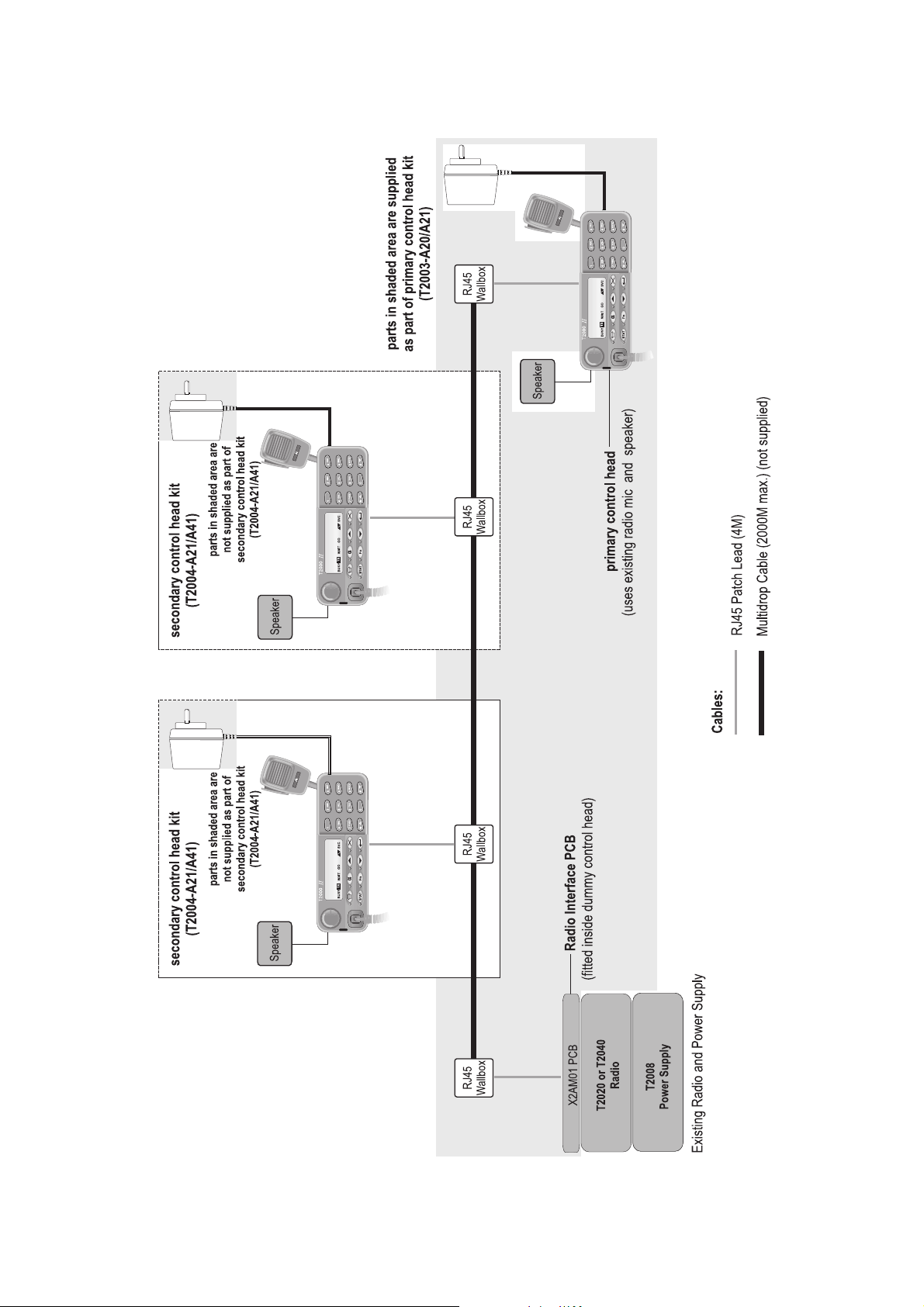
2.2 System Diagram
T2004 Multi-Control Head System Manual System Overview 15
© Tait Electronics Limited May 2004

2.3 System Equipment
The Multi-Control Head system includes the following components:
■ one T2020 or T2040 radio with T2008 power supply unit (existing)
■ 2km maximum Multidrop Line (not supplied)
■ one T2004-A20 or T2004-A40 Primary Multi-Control Head Kit
■ between one and four T2004-A21 or T2004-A41 Secondary Multi-
Control Head Kit (optional)
T2004-A20 and T2004-A40 Primary Multi-Control Head Kit Parts
The T2004-A20 or T2004-A40 Primary Multi-Control Head Kit are listed
below:
Qty IPN Description
1 X2H221 or X2H241 T2020 or T2040 Primary Control Head
1 X2AM01 T2020/40 Multi-Control Head Radio Interface
2 219-02900-00 Micromatch to RJ45 cable
2 240-04051-00 RJ45 Screw Terminal Wallbox
2 349-00010-33 Screw, #6*3/4: S/T P/P (bracket to wall)
4 349-00010-22 Screw, 4-20x3/8 P/P Trilb-P BZ (dummy head to radio)
1 316-06433-02 Dummy (Clayton’s) control head
1 316-85125-00 T2000 Plate cover
1 219-02907-00 Power/ Speaker cable (no plug pack)
1 M2004-00-000-315 Installation manual
1 252-00010-49 Microphone clip
1 302-05211-00 Head mounting bracket
2 350-01007-00 Head thumb screws
4 360-01057-00 Screw hole covers
a
b
a. For more information about the X2H221 or X2H241 Primary Control Head, see Part
B of this manual.
b. For more information about the X2AM01 T2020/40 Multi-Control Head Radio Inter-
face board, see Part C of this manual.
This kit provides the Primary control head as well as the Radio Interface
PCB. This PCB is housed inside a dummy (Clayton’s) control head and
replaces the standard control head on the radio. The radio can be concealed
if required, as all radio controls are now done via the Primary control head.
16 System Overview T2004 Multi-Control Head System Manual
© Tait Electronics Limited May 2004

A speaker and microphone are not provided as part of the Primary MultiControl Head Kit, as the Primary control head uses the speaker and
microphone already supplied with the radio.
T2004-A21 and T2004-A41 Secondary Multi-Control Head Kit Parts
The T2004-A21 or T2004-A41 Secondary Multi-Control Head Kit parts
are listed below:
Qty IPN Description
1 X2H222 or X2H242 T2020 or T2040 Secondary Control Head
1 219-02900-00 Micromatch to RJ45 cable
1 240-04051-00 RJ45 Screw Terminal Wallbox
2 349-00010-33 Screw, #6*3/4: S/T P/P (bracket to wall)
1 005-00000-40 T2000 Speaker Kit (incl. mount)
1 252-00010-76 T2000 microphone
1 219-02907-00 Power/ Speaker cable (no plug pack)
1 M2004-00-000-315 Installation manual
1 252-00010-49 Microphone clip
1 302-05211-00 Head mounting bracket
2 350-01007-00 Head thumb screws
a. For more information about the X2H222 or X2H242 Secondary Control Head, see
Part B of this manual.
a
This kit provides one Secondary control head and other equipment needed
to install the control head for use with the radio. Between one and four
Secondary Multi-Control Head Kits can be installed as part of your system.
Each control head can be installed anywhere on a multi-drop line up to
2000M long, and is powered locally by a mains-operated DC plug pack. A
speaker plugs into each control head to provide local Rx audio and Tx audio
from other control heads in the system.
T2004 Multi-Control Head System Manual System Overview 17
© Tait Electronics Limited May 2004

DC Plug packs for powering multi -control heads
Each multi-control head requires a separate DC plug pack. This is not
supplied as part of the kit because the exact plug pack requirements differ
between countries.
With each T2004 multi-control head kit you can order one of the following
plug packs
Order Code Input Voltage Country
T952-012 230V Australia/ New Zealand
T952-022 230V United Kingdom
T952-032 230V Europe
T952-042 110V United States of America
18 System Overview T2004 Multi-Control Head System Manual
© Tait Electronics Limited May 2004

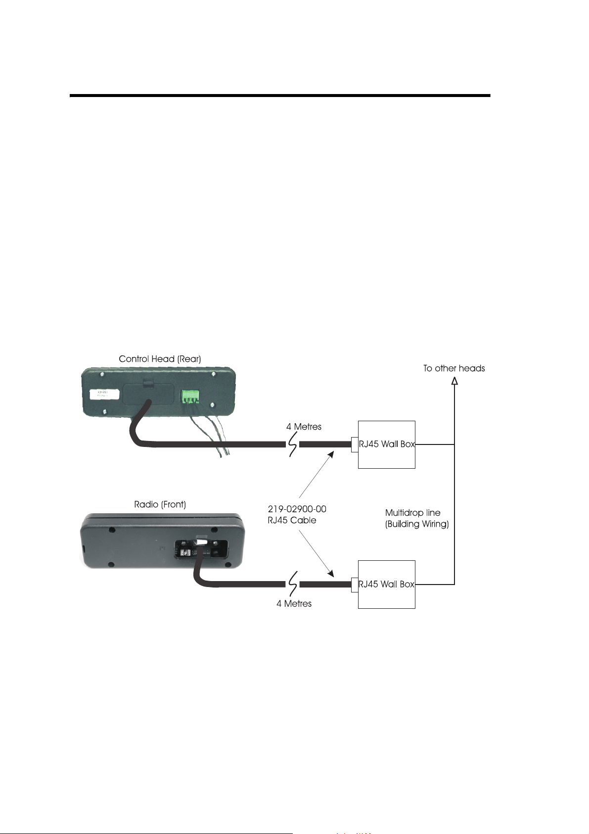
2.4 System Connections
Each control head connects to the system network via the Micromatch to
RJ45 Cable, which plugs into the RJ45 Wallbox. The RJ45 Wall boxes are
fitted at intervals along a multi-drop cable.
The radio also connects to the system network via the Micromatch to RJ45
Cable, which plugs into the X2AM01 Multi-Head Radio Interface. The
other end of the cable plugs into an RJ45 Wallbox, which is fitted at one
end of the multi-drop cable. See system diagram earlier for block overview
of system.
T2004 Multi-Control Head System Manual System Overview 19
© Tait Electronics Limited May 2004

3 System Installation
The T2004 Multi-Control Head Installation Manual M2004-00-000-315
should be referred to for the installation process.
20 System Installation T2004 Multi-Control Head System Manual
© Tait Electronics Limited May 2004

4 System Operation
The primary control head provides the same user functionality as the
original T2020/T2040 control head, including the On/Off power control
to the entire multi-head system.
The Secondary control heads have the same functionality except for the
On/Off power control. The power switch is disabled in the Secondary
heads, because only one control head (Primary) can provide system power
On/Off control.
Secondary control heads can not be individually powered off.
Note The DC plug pack for the Secondary head should be connected
to a 24-hour mains outlet in order for the Secondary heads to
always function correctly. Display errors will occur if power is
removed and replaced without resetting the radio via the Primary
head. Secondary heads have a programmed delay of 10 seconds
from initial power on, where key presses will not be actioned.
T2004 Multi-Control Head System Manual System Operation 21
© Tait Electronics Limited May 2004
5 System Equipment Specifications
5.1 Multi-Drop Cable Specifications
Note This cable is not supplied by TEL as part of the Multi-Control
Head system.
The Multi-Drop Cable is a 4x twisted pair overall screen cable (Cat5 or
similar) which is used for cabling within the building. The length of this
cable can be a maximum of 2000M.
The recommended cable type used for the multi-drop cable is M&M cables
b2004 ESCS 4 x twisted pair/overall screen.
RJ45 Wall boxes are fitted at intervals along this multi-drop cable, which
provide the junction between the remote control heads and connection to
the building network.
22 System Equipment Specifications T2004 Multi-Control Head System Manual
© Tait Electronics Limited May 2004

5.2 Micromatch to RJ45 Cable (IPN 219-02900-00)
The Micromatch to RJ45 Cable is the means by which the radio and control
heads connect to the building network.
The cable connects the radio at SK3 on the X2AM01 Multi-Head Interface
PCB to the radio’s RJ45 Wallbox. The cable connects each control head at
J5 to the corresponding RJ45 Wallbox.
The table below shows the pin assignment for the RJ45 cable which
connects to the wallboxes:
Pin Colour Description
1 Black Data from radio 1B
2 Brown Data from radio 1A
3 Red Ground
4 Orange Balanced audio
5 Yellow Balanced audio
6 Green Power switch
7 Blue Data to radio 2B
8 Violet Data to radio 2A
T2004 Multi-Control Head System Manual System Equipment Specifications 23
© Tait Electronics Limited May 2004
 Loading...