

Taema Monnal D2 Service manual

MONNAL D2
MONNAL D2
Maintenance
Manual
YM002100 - Rev 3 - December 1999
1

MONNAL D2
CONTENTS
GENERAL SAFETY INSTRUCTIONS................................................................................4
1 - GENERAL ...........................................................................................................................6
1.1 Introduction............................................................................................................6
1.2 Descriptions and Settings......................................................................................7
1.3 Specifications..........................................................................................................9
1.4 Symbols.................................................................................................................11
2 - OPERATION.....................................................................................................................12
2.1 Operating principle .............................................................................................12
2.2 Operational diagrams..........................................................................................14
2.2.1 Inspiratory phase ..............................................................................14
2.2.2 Expiratory phase ..............................................................................15
2.3 Troubleshooting...................................................................................................16
2.3.1 Ventilation problems ..........................................................................16
2.2.2 Problems originating in solenoid valve unit.......................................18
3 - DESCRIPTION .................................................................................................................19
3.1 Overall views........................................................................................................19
3.2 Compressor assembly..........................................................................................20
3.3 Compressor outlet filter box assembly ..............................................................21
3.4 Compressor valve assembly(DC1)......................................................................21
3.5 Ventilation tap assembly.....................................................................................22
3.6 Distributor assembly ...........................................................................................22
3.7 Collectors assembly..............................................................................................23
3.8 Port filter with valve assembly ...........................................................................24
3.9 Safety valve assembly..........................................................................................24
3.10 Non-return valve assembly .................................................................................25
3.11 Reservoir bag connector assembly.....................................................................25
3.12 Pneumatic connector for pressure sensor assembly........................................26
YM002100 - Rev 3 - December 1999

MONNAL D2
4 - MAINTENANCE ..............................................................................................................27
4.1 Maintenance recommendation ...........................................................................27
4.1.1 Routine maintenance...........................................................................27
4.1.2 Maintenance by technician .................................................................28
4.2 Checking procedures...........................................................................................29
4.2.1 Compressor flow.................................................................................29
4.2.2 Compressor valve (DC1) ....................................................................29
4.2.3 Bag valve ............................................................................................30
4.2.4 Safety valve.........................................................................................30
4.2.5 O2 non-return valve seal.....................................................................31
4.2.6 Distibutor ........................................................................................... 31
4.2.7 Patient flow.........................................................................................32
4.2.8 Ventilation frequency..........................................................................33
4.2.9 I/E ratio...............................................................................................33
4.2.10 Trigger threshold (SD)........................................................................33
4.2.11 Pmin disconnection alarm...................................................................34
4.3 Special tools and equipment ...............................................................................35
4.3.1 Tools ...................................................................................................35
4.3.2 Measurement.......................................................................................35
5 - DIAGRAMS.......................................................................................................................36
5.1 Pneumatic circuit diagrams................................................................................36
5.1.1 Pneumatic circuit for n° ≥ 1300..........................................................36
5.1.2 Pneumatic circuit for551 ≤ n° < 1300.................................................37
5.1.3 Pneumatic circuit for n° < 551............................................................38
5.2 Pneumatic circuit of autonomous anaesthesia system......................................39
5.3 Electrical circuit diagrams..................................................................................40
5.3.1 Electrical circuit n° ≥ 1300 .................................................................40
5.3.2 Electrical circuit 650 ≤ n° < 1300.......................................................41
5.3.3 Electrical circuit n° < 650...................................................................42
5.4 Skeleton diagrams of motherboards..................................................................43
5.4.1 Motherboard n° ≥ 1300.......................................................................43
5.4.2 Motherboard 650 ≤ n° < 1300.............................................................44
5.4.3 Motherboard n° < 650.........................................................................45
5.5 Skeleton diagram of Pmin card for n° ≥≥≥≥ 1300...................................................46
5.6 Layout diagram of components on motherboard for n° ≥≥≥≥ 1300......................47
5.7 Layout diagram of components of Pmin card for n° ≥≥≥≥ 1300............................48
6 - PARTS LIST......................................................................................................................49
7 - APPENDICES ...................................................................................................................54
YM002100 - Rev 3 - December 1999

GENERAL SAFETY INSTRUCTIONS
Use of oxygen
Keep to the safety rules for the use of oxygen:
Do not smoke,
Do not use in the vicinity of a source of sparks or incandescent objects,
Do not lubricate operating equipment
Use and servicing of the machine
Compliant with NF C 74010 (§ 1.3):
"The manufacturer, assembler, installer or the importer are not considered responsible for
the safety, reliability and the characteristics of a machine unless:
MONNAL D2
- Assembly, extensions, settings, modifications or repairs have been carried out by
persons authorised by them, and
- The electrical wiring of the relevant premises complies with IEC regulations,
- The machine is used in accordance with the instructions for use."
If the replacement parts used for the periodic servicing do not comply with the manufacturer's
specifications, the latter is absolved from all responsibility in the event of an accident.
- Do not open the machine while it is switched on.
- Do not use ether type solvents.
- Do not use pipes or tubes which are anti-static or conductors of electricity.
- Do not use in a specifically magnetic environment (MRI,etc.).
- The MONNAL D2 pulmonary ventilator must not be used with inflammable anaesthetic
materials or explosive products.
4YM002100 - Rev 3 - December 1999

GENERAL SAFETY INSTRUCTIONS
Electromagnetic compatibility
The MONNAL D2 ventilator is a medical device compliant with the protection requirements
of directive 93/42/CEE.
Its operation may be affected by the use in its vicinity of machines such as diathermy machines, high frequency electrosurgery machines, defibrillators, short-wave therapy machines or mobile telephones, and more generally by electromagnetic interference exceeding
the levels specified by standard EN 60 601-1-2 (1993 edition).
The MONNAL D2 ventilator must be associated with the necessary complementary
monitoring (O
It is recommended that a manual ventilation system (Taema type IM5 ) and an
emergency medical oxygen tank equipped with a low pressure pressure reducing
valve be kept nearby.
, flow measurement, etc.) in compliance with the regulations in force.
2
MONNAL D2
The MONNAL D2 must be used in association with a patient airways monitoring system
(Taema Pmax UNIT type).
5YM002100 - Rev 3 - December 1999
1 - GENERAL
1 . 1 Introduction
MONNAL D2
The
MONNAL D2
designed to meet the needs of anaesthetist-reanimators
who wish to use a flexible and multi-purpose ventilator:
- in the recovery room and in post-operative situations
- in anaesthesia (open-circuit)
ventilator is a machine specially
MONNAL D2
The
gas or mixture of gases (in the presence of a halogenated
agent or not).
T o constitute an
with O2 and N2O from a source of O2 gas under pressure
(or from an oxygen concentrator) and from a source of
N2O gas under pressure (and with air from the ventilator).
MONNAL D2
The
- a halogenated agent evaporator,
- a safety O
- a manual induction circuit,
- an anaesthesia table.
ventilator can ventilate a patient with a
anaesthesia system
ventilator is generally associated with:
O mixer,
2/N2
, it can be supplied
6YM002100 - Rev 3 - December 1999
1 - GENERAL
MONNAL D2
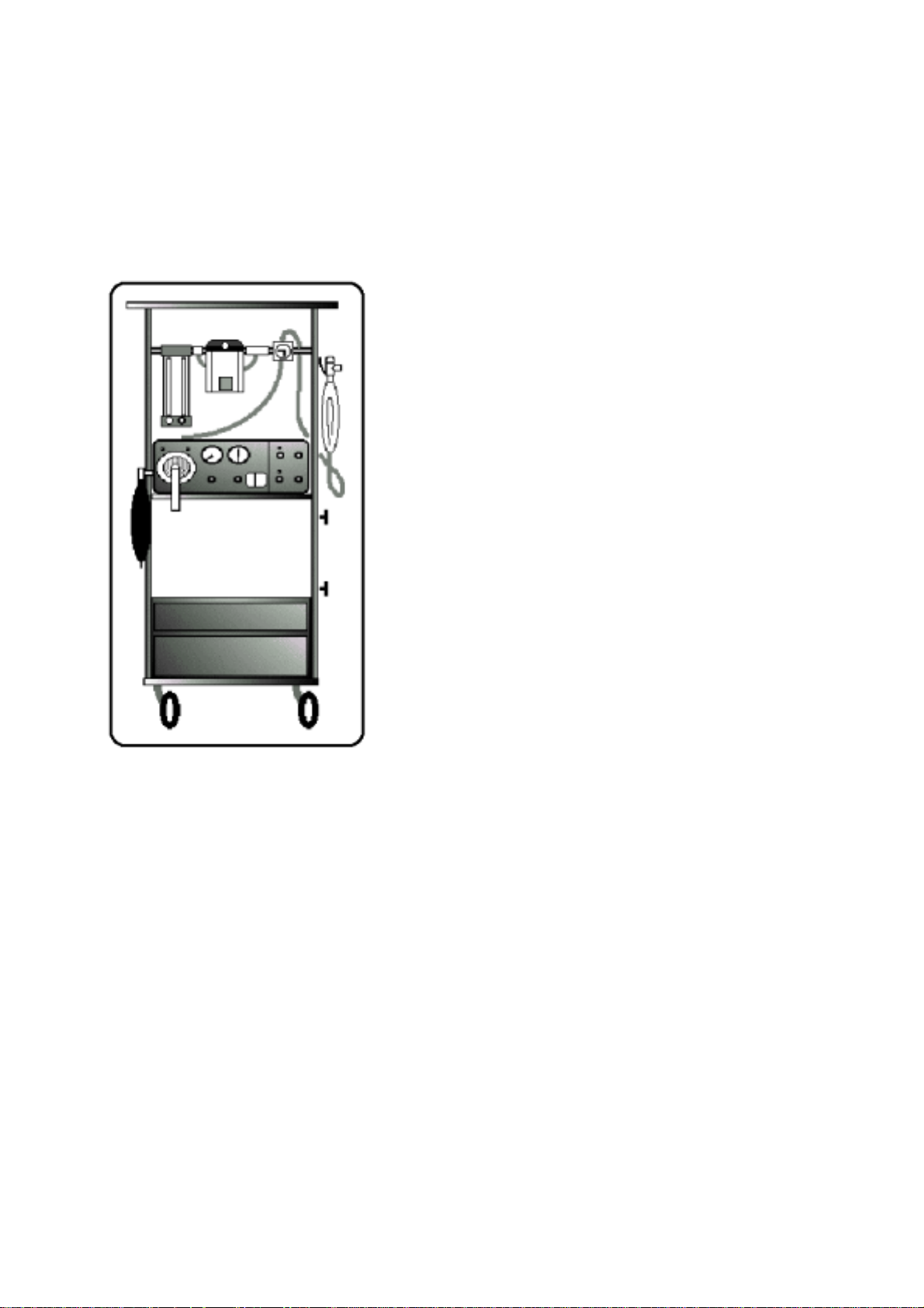
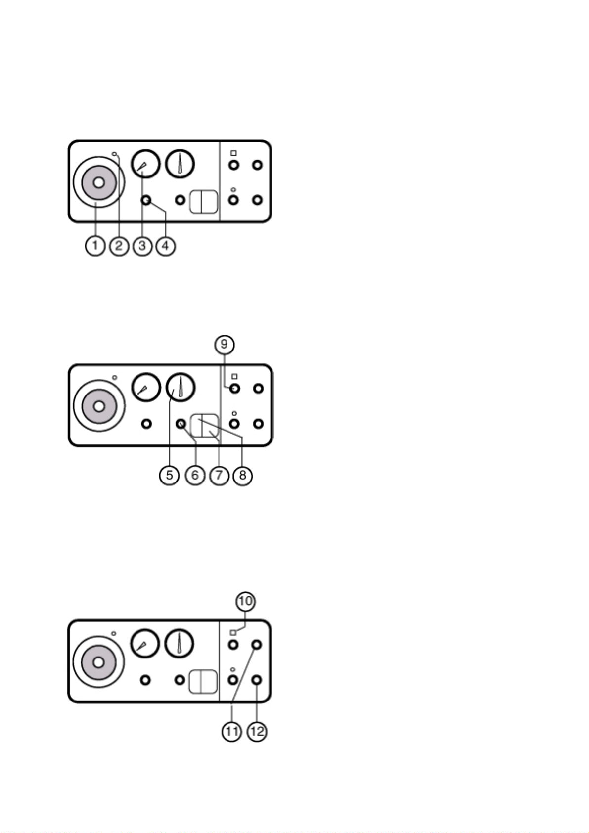
1 . 2 Descriptions and settings
FRONT PANEL
1- Bacteriological filter cover
2- Collector nozzle
Controls expiratory valve operation
3- Flowmeter for ambient air provided by
compressor
4- Air flow adjustment
5- Insufflation pressure manometer
6- Safety pressure adjustment (Pmax).
To adjust, it is necessary to:
-Block the patient circuit patient at the Y
piece
-Read off P max as it appears on the
manometer during insufflation
-adjust the setting by turning towards +/-
Note: The user may keep the P max value constant by removing the removable button
7- Green illuminated On/Off button
8- Yellow illuminated compressor start button (on
the rear panel on old models).
When the switch is in the on position, the
MONNAL D2
ambient air. Otherwise only the mixture from the
anaesthesia rack is used.
9- Pmin alarm setting
Setting by potentiometer .
10- Red LED and disabling button of Pmax.
audible alarm
When the audible and visible alarm is triggered,
pressing on the button disables the audible alarm
for 2 minutes but the red flashing LED continues
to operate.
11- I/E ratio setting
From1/3 to 1/1.
12- Frequency setting
ventilator delivers compressed
Minimum controlled cycle frequency setting.from
8 to 40 bpm.
13- Trigger sensitivity adjustment (SD/TS)
7YM002100 - Rev 3 - December 1999

1 - GENERAL
MONNAL D2
T rigger sensitivity allows Controlled Assisted Ventilation (CAV). The detection of a call sets off a
controlled cycle. If no call is detected a controlled
cycle is supplied by the machine to guarantee the
minimum set frequency
The standard SD/TS settings for CAV are
from - 1 to - 5 mbar.To move into Controlled V entilation mode (VC), set trigger sensitivity at - 20
mbar.
14- Inspiratory effort trigger
REAR PANEL
15- Hour counter
16- Water trap
17- Abacus: air and oxygen mixtures
18- Aeration
19- Mains socket
20- Fuse
2 supply protection fuses.
21- Compressed ambient air outlet nozzle
Outlet used for autonomous anaesthesia
system connection
22- Fresh gas inlet nozzle
23- Manufacturer's label
UPPER COVER CONTROL
21a - Compressed ambient air outlet control
Compressor to outlet air duct control (21) used
for autonomous anaesthesia connection.
The AIR DIRECT position corresponds to standard operation; the AIR INDIRECT position corresponds to the autonomous system
configuration.
8YM002100 - Rev 3 - December 1999

1 - GENERAL
1.3 Specifications
PHYSICAL
- Dimensions: L x D x H = 470 x 308 x 150 mm.
- Mass: 14 kg.
ELECTRICAL
- Electrical supply: 220 V~ 50 Hz
Own electrical consumption: 160 VA
Class I machine
Type B machine
MONNAL D2
- Protection at maximum current:
General supply protection: 2 F 1A fuses (rear panel),
Electronic card protection: 1 100 mAT internal fuse.
- Power failure protection:
Audible alarm (duration of discharge: 10 minutes).
ENVIRONMENT
- Minimum and maximum storage temperatures: From -40°C to +70°C.
- Minimum and maximum operating temperatures: From +10°C to +40°C.
- Atmospheric pressure (use): From 700 to 1060 mbar.
- Relative humidity (storage and use): From 30 to 75%.
- Protection index: IP20 (protected against solid bodies greater than 12 mm and non-
protected against penetration by liquids).
9YM002100 - Rev 3 - December 1999

1 - GENERAL
PERFORMANCE
- Breathing rate: From 8 to 40 bpm
- I/E ratio: From 1/1 to 1/3.
- Mean flow (insufflated per minute): From 0 to 20 l/min.
- Pmin pressure sensitivity: From 0 to 60 hPa.
- Trigger sensitivity (CAV): From 0 to -20 hP a.
- Instantaneous pressure display: From -20 to 100 hPa.
MATERIALS IN CONTACT WITH THE PATIENT AND GASES BREATHED
Silicone (autoclavable patient circuit),
Latex (accumulation bag),
MONNAL D2
PVC,
Aluminium.
STANDARDS/DIRECTIVES
NF C 74350: Artificial respiration treatment machines
NF S 90-118: Medical use ventilators
NF EN 601-1: Electromedical machine safety
NF EN 60-601-1-2: Electromagnetic compatibility of electromedical machines.
European directive 93/42/CEE concerning medical devices.
10YM002100 - Rev 3 - December 1999

1 - GENERAL
1.4 Symbols
/ T rigger Trigger sensitivity
MONNAL D2
Stop (power off)
Start (power on)
Pmin audible alarm disable
Ratio of inspiration phase to expiratory phase
Breathing rate (frequency)
organisation n° 0459).
(
MONNAL D2
Protection earth
Equipotential
Attention: Refer to accompanying documents
Type B machine
Compliance with directive 93/42/CEE (established by notified
units are systematically marked starting from serial number 1770)
11YM002100 - Rev 3 - December 1999
2 - OPERATION
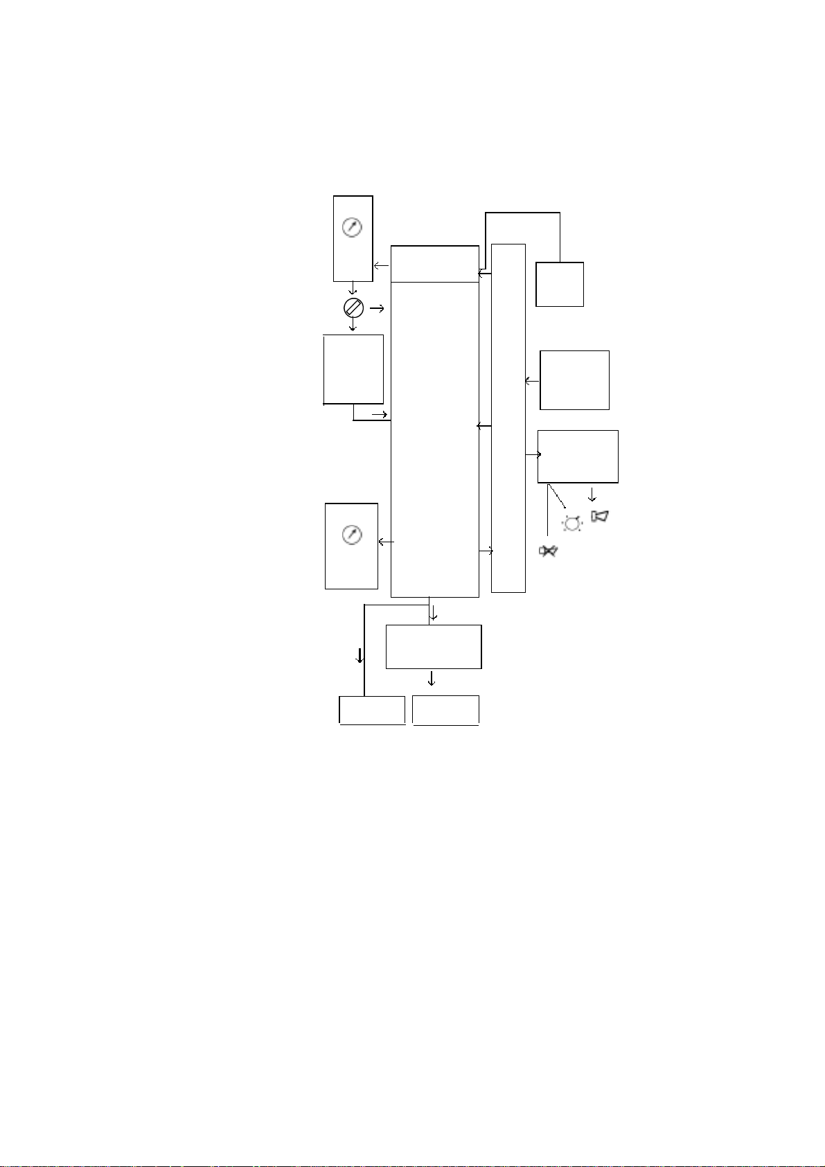
2.1 Operating principle
MONNAL D2
l/min
0 20
V
Anaesthetic
mixture or
O
2
mbar
-2 100
pressure
Compressor
Collector
block
Solenoid valves
Reservoir
bag
Safety
valve
Bacteriological
filter
unit
Electronic
0/1
compr.
f, I/E,
Pmin, TS
Settings
Pmin, mains
Alarms
Collector Patient
Operating diagram
The collector/solenoid block is supplied with air, and/or with a gas mixture (or with pure
oxygen), by means of a compressor.
Air ventilation (V) is displayed on a flowmeter and controlled by a tap.
The collector block including diaphragms associated with solenoid valves, controlled by the
electronic unit, distributes the continuous flow
- on one hand, towards the reservoir bag during the expiratory phase,
- on the other hand, with the addition of gas stored by the bag, towards the patient
through a bacteriological filter during the inspiratory phase.
The insufflation pressure is displayed on a manometer and can be limited by adjusting a
safety valve.
By means of the electronic unit the rate, the I/E ratio, the trigger sensitivity SD/TS (in CAV
mode) and Pmin sensitivity can be set. It also enables visual indication of the trigger sensitivity
SD/TS, audible and visual indication of Pmin, and audible indication of a mains power cut.
12YM002100 - Rev 3 - December 1999

2 - OPERATION
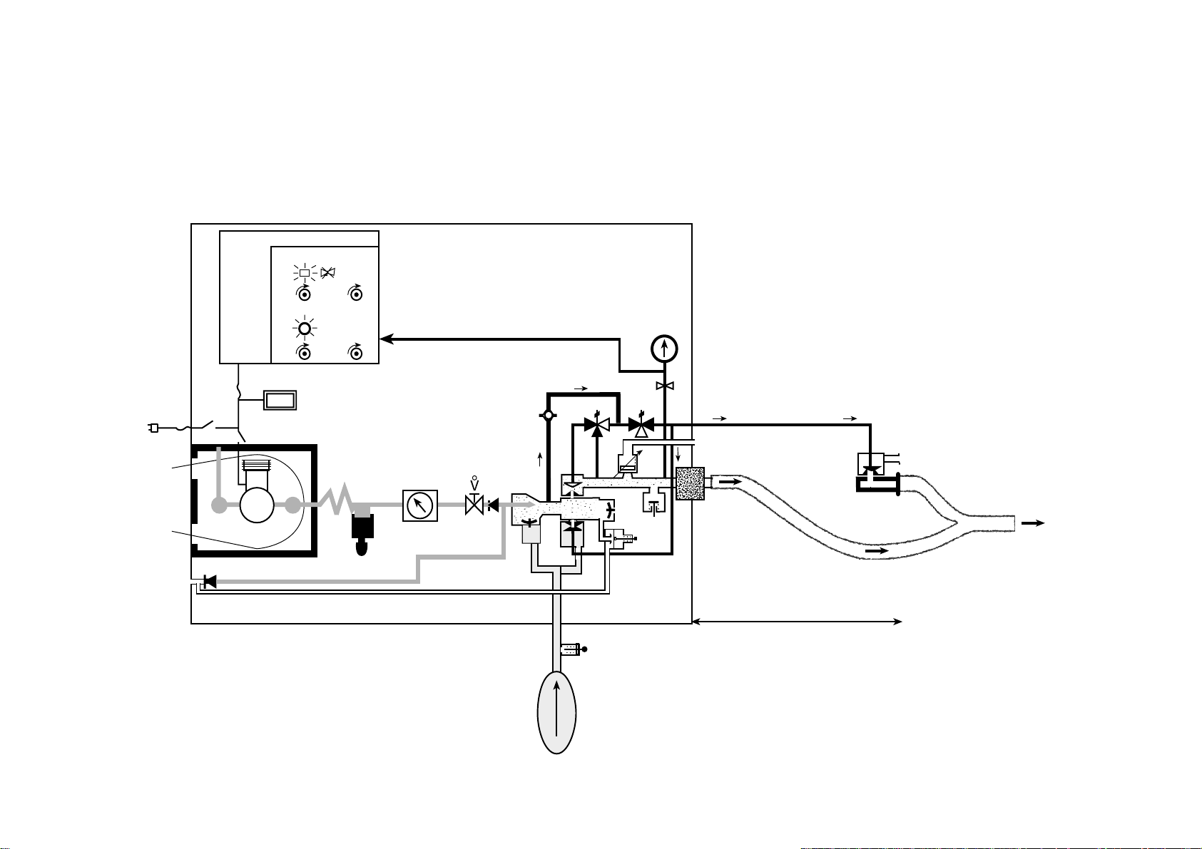
DESCRIPTION OF VENTILATION PHASES
Inspiratory phase
The patient receives the continuous flow from the compressor or from the fresh gas inlet
nozzle to which are added, by the Venturi effect, the gases which have accumulated in the
reservoir bag during the inspiratory phase.
The reservoir bag deflates.
If resistance is felt, the pressure in the patient circuit reaches the Venturi discharge pres-
sure, in which case the bag's non-return valve shuts, and this allows the compressor to
increase the insufflation pressure if necessary. This pressure is, however, limited to the
value of the patient safety valve setting.
Expiratory phase
The patient circuit is isolated from the machine, and the patient breathes out freely towards
the outside, through the expiratory valve.
MONNAL D2
Meanwhile the circuit towards the reservoir bag opens and the bag inflates.
The pressure in the bag is in any case limited to the opening pressure of the overpressure
valve.
AIR AND OXYGEN MIXTURE
If an additional supply of 100% oxygen is insufflated to the patient when the compressor is
operating, this oxygen flow is added to the air flow set on the manometer on the front panel.
O
l/min
2
13YM002100 - Rev 3 - December 1999
Pmini
I/E
2.2.1 Inspiratory phase
2.2 Operating diagrams
2 - OPERATION
220 V
Fresh
gas
Hour counter
Compressor
SD
F
0-20 l/min
550 mbar
Filter
0 +80
mbar
110 mbar
-20 + 100
mbar
-
-20 mbar
170 mbar
+
PATIENT
MONNAL D2
PATIENTCIRCUIT
14YM002100 - Rev 3 - December 1999

Pmini
2 - OPERATION
2.2.2 Expiratory phase
I/E
220 V
Fresh
gas
Hour counter
Compressor
SD
F
0-20 l/min
550 mbar
Filter
0 +80
mbar
110 mbar
-20 + 100
mbar
-
-20 mbar
170 mbar
+
PATIENT
MONNAL D2
PATIENT CIRCUIT
15YM002100 - Rev 3 - December 1999

2 - OPERATION
2.3 Troubleshooting
2.3.1 Ventilation problems
MONNAL D2
OBSERVATIONS
No ventilation
The compressor does not
operate, the clock is not
working and there is no
“mains power fault” alarm.
The compressor does not
operate, the clock is not
working, but the “mains
power fault” alarm trips.
The compressor does not
operate, but the clock is
working.
SYMPTOMS
- On/Off button not pressed
in.
- Defective electronic unit.
- No electrical supply.
- Defective machine supply
fuse(s).
- Compressor on/off switch
not engaged
- Compressor overheating
(internal thermal circuit
breaker tripped).
REMEDIES
- Press the on/off button.
- Replace the unit.
- Check that the machine is
properly plugged in.
- Replace the F1A fuse(s).
- Switch on the compressor
(switch on rear panel on old
models).
- Check the air vents
- Recondition or replace the
compressor.
The compressor operates,
but the reservoir bag does
not inflate and the Pmin
alarm trips.
The compressor operates,
the reservoir bag inflates
and deflates, but the Pmin
alarm trips.
The compressor operates
but the clock is not
working and the “mains
power fault” alarm trips.
- Ventilation button is in off
position (flowmeter shows 0)
and the fresh gas supply is
zero.
- Automatic triggering at
wrong time.
- Expiratory valve
malfunction.
- Defective patient circuit.
- Defective fuse.
- Defective electronic unit.
- Open the ventilation tap
and/or supply the MONNAL
D2 with fresh gas.
- Press the SD (TS) button
(trigger sensitivity).
- Check the expiratory
diaphragm and its tube.
- Check the patient circuit
very carefully.
- Replace the F100 mA fuse
- Replace the unit.
16YM002100 - Rev 3 - December 1999

2 - OPERATION
MONNAL D2
OBSERVATIONS
Insufficient ventilation
Failure of Controlled
Assisted Ventilation
The “TRIGGER” LED is
permanently lit up.
The “TRIGGER” LED
does not light up.
SYMPTOMS
- Leak on patient circuit.
- Bacteriological filter assembly
not airtight.
- Expiratory valve collector
wrongly connected.
- Automatic triggering.
- Trigger sensitivity set around 20 mbar.
- Electronic defect.
REMEDIES
- Check patient circuit
assembly.
- Disassemble and reassemble the assembly.
- Check the collector and
its membrane.
- Set the trigger sensitivity
correctly (SD/ TS).
- Set the trigger sensitivity
correctly .
- Check the power supply
to the LED and/or Replace
the electronic unit.
Failure of Controlled
Ventilation
The “TRIGGER” LED
lights up.
Failure of Pmin
disconnection alarm
The Pmin alarm is
permanently triggered.
The Pmin does not trigger.
No humidification
(models with humidifier
socket)
- Ventilatory parameters
wrongly set.
- Wrong setting.
- Leak on the pressure sensor
circuit.
- Electronic defect.
- Humidifier not connected.
- Humidifier socket fuse blown.
- Set the ventilatory
parameters correctly.
- Set the Pmin sensitivity
correctly.
- Check that there are no
internal leeks.
- Replace the Pmin card.
- Plug in the humidifier
card.
- Replace the fuse.
17YM002100 - Rev 3 - December 1999
 Loading...