

Page 1

Owner ’s Manual
TCS mkII
Preamplifier / Theater Correction System
Page 2

Blank Page
Page 3
WARNING
TO REDUCE THE RISK OF FIRE OR ELECTRIC SHOCK, DO
NOT EXPOSE THIS APPLIANCE T O RAIN OR MOISTURE.
CAUTION
RISK OF ELECTRIC
SHOCK DO NOT OPEN
CAUTION: TO REDUCE THE RISK OF ELECTRICAL SHOCK,
DO NOT REMOVE COVER. NO USER-SERVICEABLE PARTS
INSIDE. REFER SERVICING TO QUALIFIED PERSONNEL.
The exclamation point within an equilateral triangle is intended to alert
the user to the presence of important operating and maintenance (servicing) instructions in the literature accompanying the product.
The lightning with arrowhead symbol within an equilateral triangle is
intended to alert the user to the presence of “Dangerous Voltage”
within the product’s enclosure that maybe of sufficient magnitude to
constitute a risk of electrical shock to a person.
3T act Audio
Page 4
Important Safety
Instructions
1. Read these instructions entirely before installing or operating this equipment.
2. Keep these instructions.
3. Heed all warnings.
4. Do not use this equipment near water or allow it to become wet.
5. Do not block any ventilation openings. Install in accordance with the
manufacturer’s instructions.
6. Do not install near any heat sources such as radiators, heat registers, stoves, or
other appliances (including amplifiers) that produce heat,; doing so may
damage the unit and present a fire hazard.
7. Do not defeat the safety purpose of the polarized or grounding-type plug. A
polarized plug has two blades with one wider than the other. If the provided plug
does not fit into your outlet, consult an electrician for replacement of the outlet to
one that is polarized. To protect against electrical shock, match the wide blade
of the polarized plug to the wide slot in the outlet and fully insert the plug.
8. Protect the power cord from being walked on or pinched, particularly at plugs,
convenience receptacles, and the point where they exit the equipment. Do not
use this unit with a damaged cord or plug.
9. Only use attachments/accessories specified by the manufacturer .
10. Unplug this equipment during lightning storms or when unused for long periods of
time.
11. Refer all servicing to qualified service personnel.
1. Always unplug the unit from the electrical outlet before cleaning.
2. Do not use abrasive cleaners. Simply wipe the exterior with a clean soft cloth. A
small amount of nonabrasive cleaner may be used on the cloth to remove
excessive dirt or fingerprints.
CAUTION
“Note” symbol
4 T act Audio
Cleaning and
Maintenance
The >note< symbol indicates information very useful or essential to daily
operation.
Page 5

Acknowledgments
TCS is manufactured under license from Dolby Laboratories Licensing Corporation,
confidential unpublished works 1992-1997. “Dolby”, the double-D symbol, and “Pro
Logic” are trademarks of Dolby Laboratory .
TCS is manufactured under license from Digital Theater Systems. “DTS” and DTS
symbol are trademarks of Digital Theater System.
© 2003 T act Audio Corporation. All rights reserved.
No part of this document may be reproduced or transmitted in any form or by any
means, electronic, mechanical, photocopying or other wise, without the prior
written consent of the Tact Audio Corporation.
The information contained in this document is subject to change without
notice.
IMPORTANT!
Registration
Please record your serial number here for future reference. Y ou will need this for
future upgrades or should you ever require service on your TCS mkII Multichannel
Preamplifier.
TCS mkII serial number: _____________________
5T act Audio
Page 6

Table of contents
Safety instructions 4
Acknowledgments/Registration 5
Unpacking the TCS mkII 7
Introduction 8
TCS mkII Connections 10
Remote Control 1 2
Getting Started 1 4
Front Panel Display 1 8
Main Menu 20
Saving Menu Settings 20
SETUP menu 21
LEVEL menu 30
DELA Y menu 31
ADL Y menu 32
POL menu 33
APOL menu 34
TEST menu 35
LINK menu 36
TRIG menu 3 7
DISPL menu 38
PLII menu 39
STP menu 40
DRC menu 41
ADC menu 42
AMP menu 4 3
OUTFS menu 44
LCRO menu 45
LFCRO menu 46
ADDR menu 4 7
POWER menu 48
LOCK menu 49
OPT menu 50
VER menu 5 2
CAUTION
6 T act Audio
TCS mkII Theater Correction Software 53
System Requirements 53
Software Installation 53
Microphone Installation 53
Connect your TCS mkII to
your Computer 54
Setup Presets 55
Setup Tutorial 60
Page 7

Unpacking the TCS mkII
Carefully remove the TCS mkII and accessory kit from the carton and visually check
for shipping damage. Contact both the shipper and Tact Audio immediately if the unit
shows any sign of damage from rough handling. All Tact Audio equipment is carefully
inspected before leaving our factory .
KEEP THE SHIPPING CART ON AND P ACKING MATERIALS for future use or in the
unlikely event that the unit needs servicing. If this unit is shipped without the original
packing, damage could occur and void the warranty .
Accessories
Operating voltage
Y ou should find the following items in the accessory kit:
- one AC mains cord
- RJ1 1 data cable
- RJ11-to-RS232 adapter
- 15’ RS232 cable
- CD-ROM with RCS software
- Measurement microphone
- remote control
- 2 AAA batteries
- this manual
The TCS mkII is designed with an automatic switching power supply . It will operate on
65-265 volts at 50-60hz. No external settings are required.
The TCS mkII has three operating modes:
- OFF AC mains power is cut off, either via the front
panel mains switch, or by unplugging the unit from the
wall outlet.
- ST ANDBY The unit is powered but all outputs are muted and the
display is off. The unit uses very little current and
is “idling” or “sleeping”. Use the remote control
“STANDBY” button to toggle between ON and STANDBY.
- ON Everything is powered and ready to go.
7T act Audio
Page 8
Introduction
CAUTION
Congratulations on your purchase of your TCS mkII. Y ou have now acquired the most
advanced Preamplifier and Room Correction System ever developed!
The TCS mkII Theater Correction System is designed to decode Dolby and DTS
surround soundtracks while implementing the world renowned Tact Theater
Correction for the most remarkable theater experience ever. The TCS mkII offers
nine digital and seven analog stereo inputs as well as one microphone input used
for theater response measurement. The TCS mkII also provides 10 analog and 10
digital output channels and can decode up to eight channels of digital encoded
audio.
The TCS mkII manual will guide you through using the unit’s front panel controls
and explain how to connect it to your system. In order to enjoy the TCS mkII’s full
capabilities you will need to install the TCS mkII Theater correction software,
perform a room measurement and calculate room correction settings. The
correction process itself is detailed in the TCS mkII software online help and it is
strongly recommended that you install the software and first review its help file to
gain an understanding of the correction process before you operate your TCS mkII.
The TCS mkII architecture allows for high flexibility in surround sound loudspeaker
configuration. By combining a powerful bass management processor with room
correction capabilities the TCS is the ultimate choice for any high-end home
theater installation.
To get the most out of your digital theater system, we suggest combining the TCS
mkII with Tact digital amplifiers. In this all-digital audio system, the signal stays in
the digital realm until it reached the DACs at the amplifier output posts. This
maintains the ultimate in signal purity. Please contact us or visit our web site
www.t actaudio.com for more information.
8 T act Audio
Page 9

TCS mkII - Introduction
TCS mkII highlights:
• Decoding for Dolby® Digital EX, DTS® ES, Dolby Pro Logic® II, and
DTS® neo:6.
• Analog output s are designed with exceptionally high quality 24 bit
digital-to-analog converters. All ten analog outputs are available in RCA-single
ended connectors and the Left, Right, and Center outputs are also available in
XLR-balanced form.
• Analog input s are converted to digital signal by high-quality 24 bit
analog-to-digital converter. There are 6 RCA-single ended stereo pairs and 1
XLR-balanced stereo pair . These inputs provide for two channel analog source
input.
• Proprietary digital input for use with the optional Tact TCS ADC 6. The TCS
ADC 6 provides six discrete channel’ s of analog to digital conversion for
integrating your SACD and DVD-Audio components with the TCS mkII.
• All output channels are available in digit al format. The TCS mkII provides five
digital SPDIF and AES/EBU stereo outputs.
• The Tact Room Correction algorithm can be applied to all surround sound
channels. This powerful feature allows you to custom tailor your room
response to tame response irregularities caused by the interaction of the room
itself. It provides all the necessary tools and software for complete room
impulse response measurement and user-defined room correction.
• 10 separate correction presets including bypass. With a single click on the
remote control you can switch between bypass and correction for instant A-B
comparisons.
• Electronic crossover on the front Left/Right and LFE channels including the
subwoofers. You select the cutoff frequency and filter slope, and such is
accomplished in the digital domain by TCS software.
• Automatic or manual time alignment with 10 microsecond precision.
• Digital level trimming for each output channel with a resolution of 0.1 dB.
• Master volume control with steps as fine as 0.1 dB.
• Polarity control on all channels.
• Thirty different setup configuration presets with eight predefined and the
remaining 22 user programmable.
• Two individually fully programmable 12V/50 mA trigger output s.
• T act propriet ary Master V olume Control with the unique “T acT WHEEL”
displaying the volume level and type of decoding in use.
9T act Audio
Page 10
10 T act Audio
D1 D2
D3 D4
TCS mkII Connections
L
R
R
L
D7
D5 D6
D8
MIC.
DIGITAL IN ANALOG IN
INPUT
D9
1
L
7
R
2
3
L + R
SL + SR
CEN + LFE AUX 1 + AUX 2
DIGITAL OUT
4
5
6
L
R
L
ANALOG OUT
CEN
R
L
R
SL
SR
AUX 3 + AUX 4
CEN
AUX 1 AUX 3
AUX 2
LFE
AUX 4
AUX INPUT
T2
T1
CAUTION
RS232
Page 11

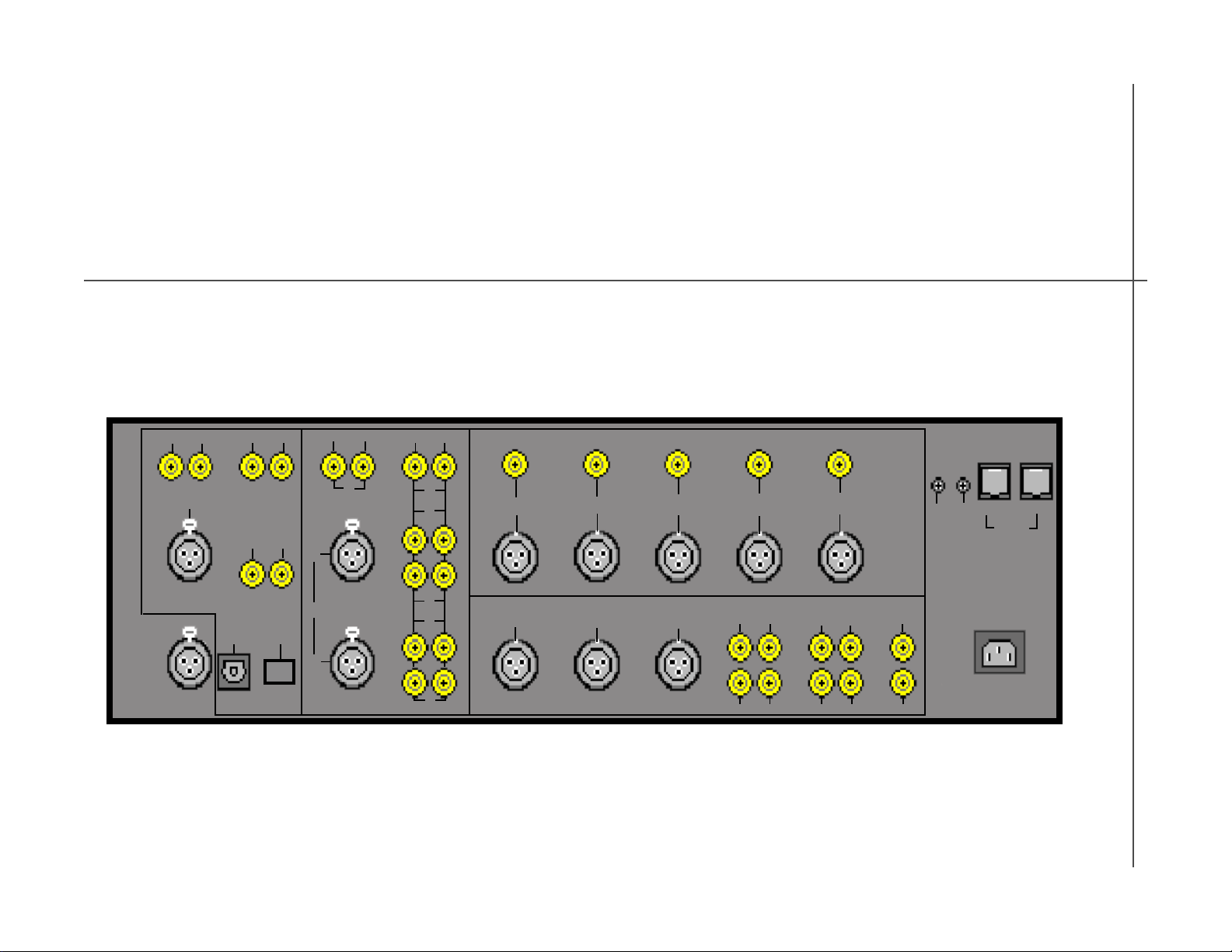
TCS mkII Connections
DIGIT AL IN
There are nine digital inputs.
- D1 - D6: SPDIF
- D7: AES/EBU
- D8: TOSLINK
- D9: Proprietary firewire connection for the Tact six channel A/D converter
DIGIT AL OUT
There are ten digital outputs, five SPDIF and five AES/EBU. Both sets of five
outputs mirror the same ten output channels. Different connection formats are
provided to accommodate different system connections.
- L + R: SPDIF, AES/EBU
- SL + SR: SPDIF, AES/EBU
- CEN + LFE: SPDIF, AES/EBU
- AUX 1 + AUX 2: SPDIF, AES/EBU
- AUX 3 + AUX 4: SPDIF, AES/EBU
ANALOG IN
There are seven stereo analog inputs.
- 1- 6: RCA single ended stereo pair
- 7: XLR balanced stereo pair
ANALOG OUT
There are thirteen analog outputs. There are single ended outputs provided for all
ten output channels and three balanced connectors are provided for the L, R, and
CEN outputs. The balanced outputs mirror the L, R, and CEN single ended
outputs and are provided to accommodate different system connections.
- 10 RCA single ended: L, R, SL, SR, CEN, LFE, AUX1, AUX2, AUX3, AUX4
- 3 XLR balanced: L, R, CEN
MIC. INPUT
TCS mk II comes with a calibrated measurement microphone. During the
setup process, the microphone should be connected to the MIC input.
- Pin 1 GND
- Pin 2 SIG
- Pin 3 +9V
CAUTION: Before connecting or disconnecting Tact measurement
microphone make sure to turn TCS off by using the front panel power switch.
RS232 I/O
There are two RS232 connectors.
INPUT is used to connect to the PC during the setup process or for a RS232
remote control.
AUX is used as the RS232 pass-through to daisy chain a number of Tact products.
Trigger Output s
There are two trigger T1 and T2 outputs that provide a +12V/50mA signal for
external device triggering.
11T act Audio
Page 12
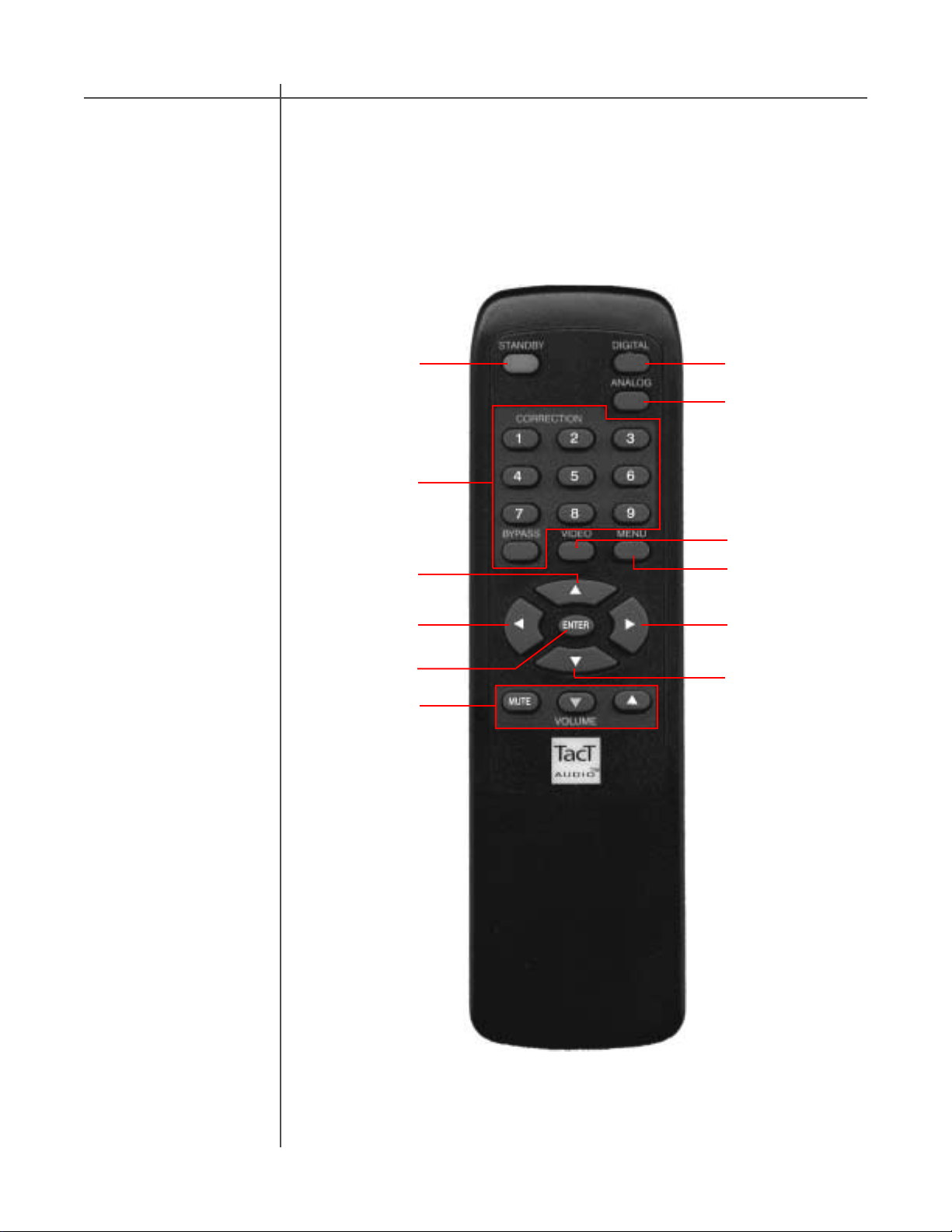
Remote Control
The remote control is used to access the front panel display controls and menus.
CAUTION
11
12
1
4
7
9
2
3
5
6
10
8
12 T act Audio
Page 13

Remote Control
1 - ST ANDBY
The ST ANDBY button will turn the TCS mkII ON or it will place it into st andby
mode. When in standby mode, the unit is placed into a low power “idling” state.
The main power line is not disconnected.
2 - DIGIT AL
The DIGIT AL button will scroll sequentially , allowing the selection one of the 9
digital inputs.
3 - ANALOG
The ANALOG button will scroll sequentially, allowing the selection one of the 7
analog inputs.
4 - CORRECTION block
The CORRECTION block consists of 10 buttons. The buttons are numbered from 1
to 9 and one BYP ASS. Pressing the BYPASS button will bypass room correction.
Pressing any of the remaining nine buttons will engage the corresponding room
correction you have preset.
5 - MENU
The MENU button will switch the front panel display from the status screen to the
main menu screen. By pressing the MENU button again you will exit the menu
that you are currently viewing and eventually will return to the main status screen.
6. VIDEO
The VIDEO button is used to enable and disable the remote control. Pressing the
VIDEO button will toggle the enable and disable remote control state.
7. UP
The UP navigational button is used to select menu options and/or change their
values.
8. DOWN
The DOWN navigational button is used to select menu options and/or change their
values.
9. LEFT
The LEFT navigational button is used to select menu options and/or change their
values.
10. RIGHT
The RIGHT navigational button is used to select menu options and/or change their
values.
11. ENTER
The ENTER button will select the menu option currently marked by the blinking
cursor or is used to enter an edited parameter .
12. VOLUME Block
The VOLUME block consists of three buttons.
The “MUTE” button will mute/un-mute all enabled channels.
The “UP” button will increase the master volume level
The “DOWN” button will decrease the master volume level.
13T act Audio
Page 14
Getting Started
The Getting Started section of the manual is intended to provide basic instruction
for using the TCS mkII without performing room correction. It will allow you to
quickly setup your system and perform basic listening tests.
IMPORT ANT : All listening performed before completing the room correction
process should be done with TCS in room correction BYP ASS mode.
CAUTION
Step 1:
Connecting The
TCS mkII to your
system
Connecting The
TCS mkII to your
system
Step one will guide you through connecting the TCS mkII to your system. The TCS
mkII audio connections are divided into four main sections: Digital input, Analog
input, Analog output, and Digit al output.
Analog and Digital inputs
The TCS mkII supports nine digital and seven stereo analog inputs. Below is a
listing of available inputs. Please connect your digital sources (such as DVD and
CD players) to the TCS mkII digital inputs and your analog sources (such as tuners
and tape-decks etc.) to the TCS mkII analog inputs.
Digital inputs:
- 1-6 : SPDIF
- 7: AES/EBU
- 8: TOSLINK
- 9: Proprietary firewire connection for the Tact TCS ADC 6. (Sold Sep arately)
Analog inputs:
- 1-6: RCA single ended stereo pair
- 7: XLR balanced stereo pair
Analog and Digital outputs
The TCS mk II offers a number of different digital and analog output connections. All
analog outputs should be connected to the appropriate analog power amplifiers. If
you have digital amplifiers, or if you use an external DAC use the appropriate digital
outputs. The channel key below explains the output code and channel assignment
for the T act predefined setup presets.
14 T act Audio
Channel Key:
L - left LFE - LFE
R - right AUX1 - surround center left
SL - surround left AUX2 - surround center right
SR - surround right AUX3 - right subwoofer
CEN - center AUX4 - left subwoofer
Digital Outputs:
- 5 RCA SPDIF: L/R, SL/SR, CEN/LFE, AUX1/AUX2, AUX3/AUX4
- 5 AES/EBU: L/R, SL/SR, CEN/LFE, AUX1/AUX2, AUX3/AUX4
Analog Outputs:
- 10 RCA single ended: L, R, SL, SR, CEN, LFE, AUX1, AUX2, AUX3, AUX4
- 3 XLR balanced: L, R, CEN
Page 15
Getting Started
Step 2:
Power On
Main Status Screen
Step two will guide you through powering up your TCS mkII and give a brief overview
of the Main Status Screen that is displayed when the unit is powered on.
Connect the Power cable supplied with the unit to the TCS mkII and plug it into
your power source outlet. Power on the TCS mkII by turning on the master power
switch on the back of the unit and then press the main power button found on the
front of the unit. The status screen should now be displayed. An example of this
screen is shown below.
The main screen displays the current operating status for the TCS mkII and is
displayed when the TCS is powered on. Below is a brief description of the Main
St atus Screen indicators. A detailed explanation of the Main S t atus Screen can be
found in the Main Status Screen section of this manual.
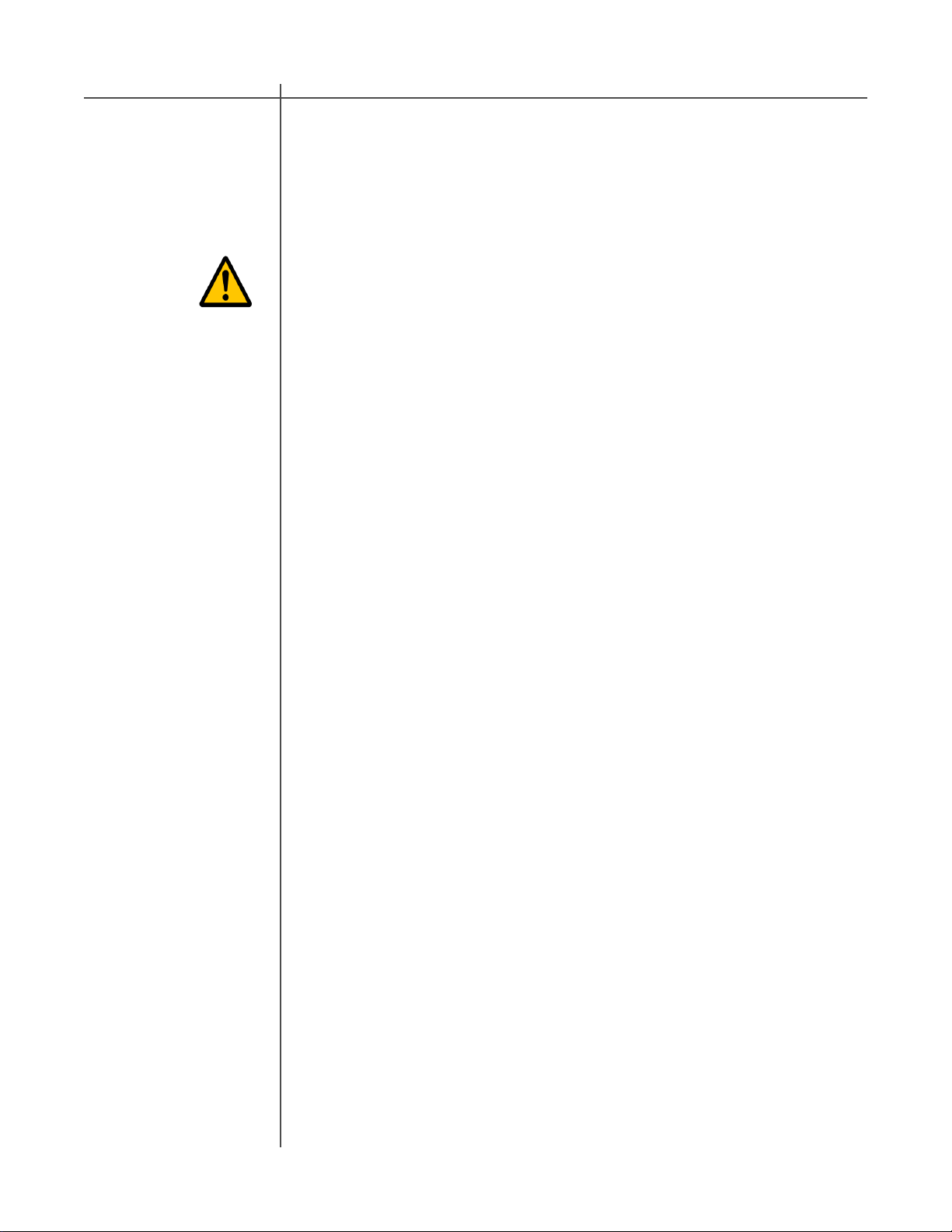
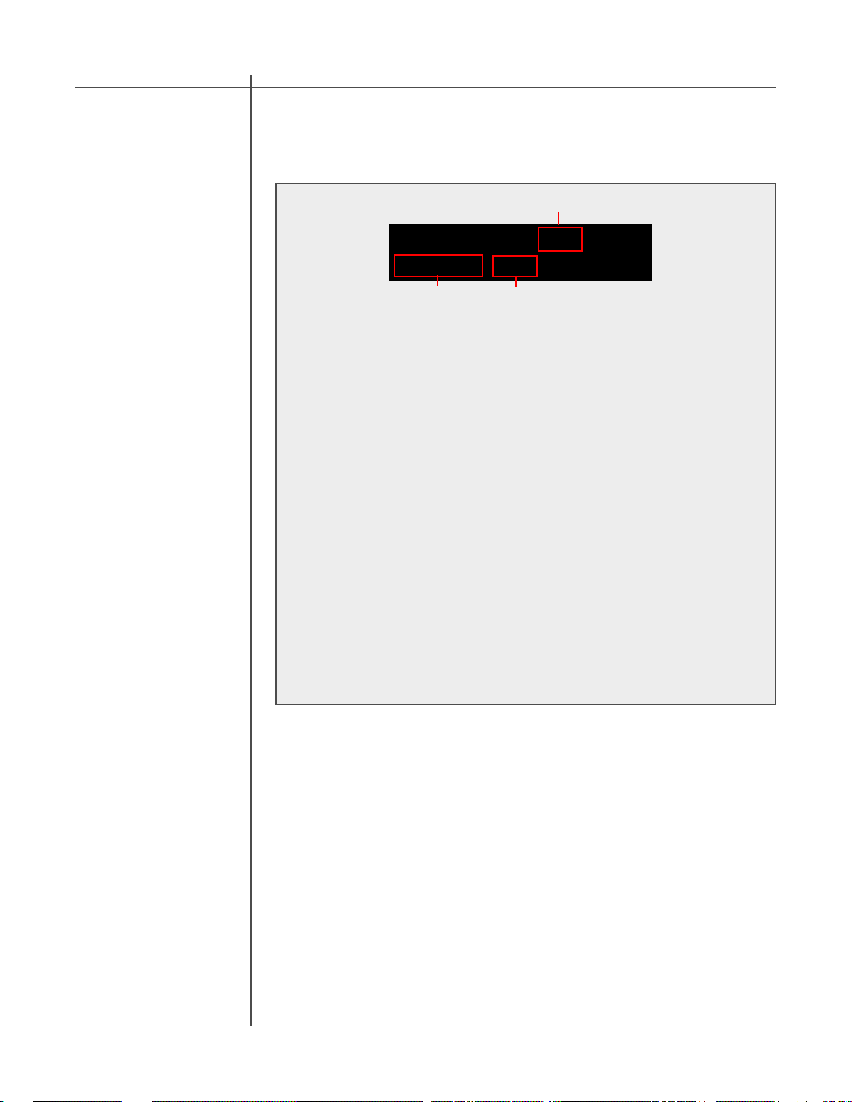
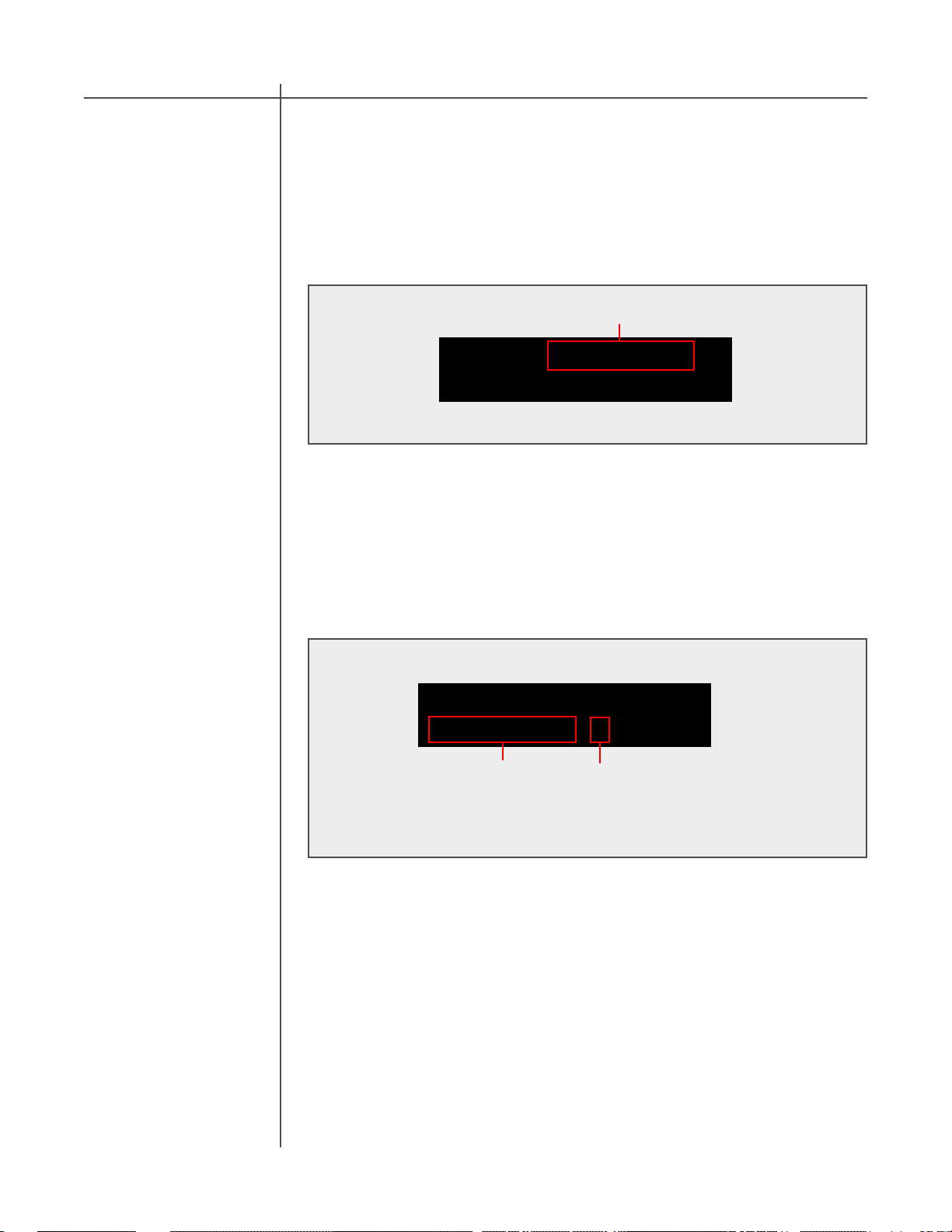
Main Screen :
12 3
4
3/2 LFE D1 44.1
Cor:BP S:1 -33.1dB
5
1 - Signal Mode Indicator
2 - LFE Indicator
3 - Active Input Indicator
4 - Digital Input Frequency Indicator
5 - Correction Indicator
6 - Setup Indicator
7 - Master level in dB
6
7
1- Signal Mode Indicator
The TCS mkII will auto-detect the digital signal being sent to the selected input and
display the type of digital signal found in the signal mode indicator display .
2 - LFE Indicator
The LFE indicator indicates whether or not a low frequency channel signal is present
in the digital signal that is being decoded.
3 - Active Input Indicator
The active input indicator displays the active input selected.
4 - Digital Input Frequency Indicator
This displays the sampling frequency of the selected digital input. The TCS mkII will
automatically detect input signal presence and display its’ sampling frequency.
5 - Active Correction Indicator
The active correction indicator displays the active correction preset.
6 - Active Setup Indicator
The active setup indicator displays the active setup preset. The TCS mkII has thirty
setup presets. The SETUP preset defines the unit’s output channels, signal routing,
and bass management configuration. This feature allows for extremely powerful
control over the configuration of the unit. The Setup selection and creation will be
explained in full detail later in this manual.
7 - Master level in dB
This displays the master volume level in dB.
15T act Audio
Page 16
Getting Started
Step 3:
Open the Setup
Menu
Step three illustrates selecting a SETUP preset. The TCS mkII SETUP preset
defines the unit’s output channels, signal routing, and bass management
configuration. There are a total of thirty preset configurations available. A detailed
description of the Setup presets and how to edit them can be found later in this
manual.
For the Getting Started section we suggest selecting either the “1. Dolby 1” or “5.
T act 1” setup preset. An explanation of theses setups can be found below . Please
select the preset that best matches your system’s setup.
1. Dolby 1: Is designed for 10 output channels or less with small speakers in all
positions and an LFE subwoofer. Choose this setting if you have 10 or less small
speakers and want all low frequencies below 100 Hz from all channels to be
reproduced by the LFE channel only . This setup applies bass management
filtering to redirect the low frequencies and high frequencies to the proper output
channels.
5. T act 1: Is designed for 10 output channels or less with large speakers in all
positions and an LFE subwoofer. Choose this setting if you have 10 or less larger
speakers. This setup applies no bass management filtering and will send full range
signals to all outputs.
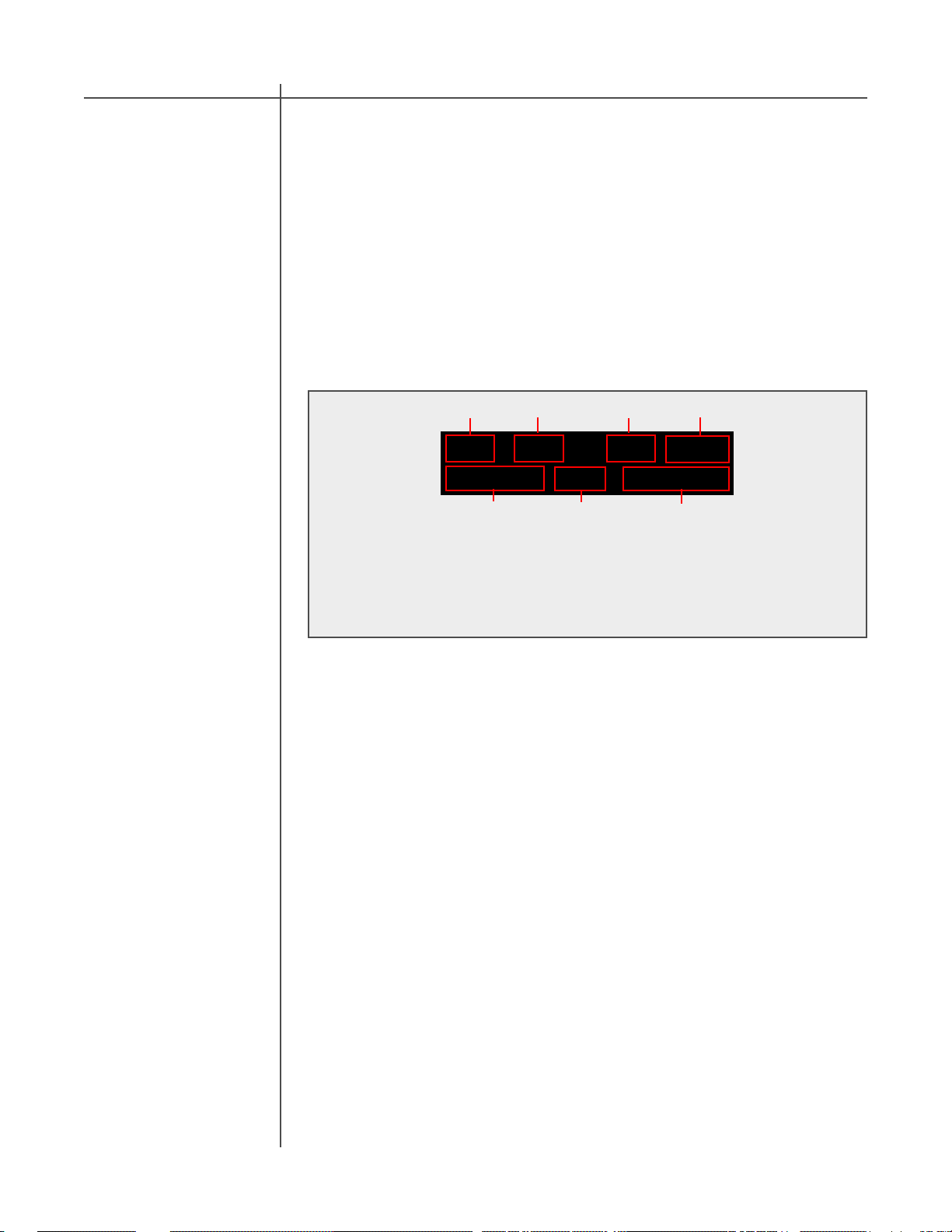
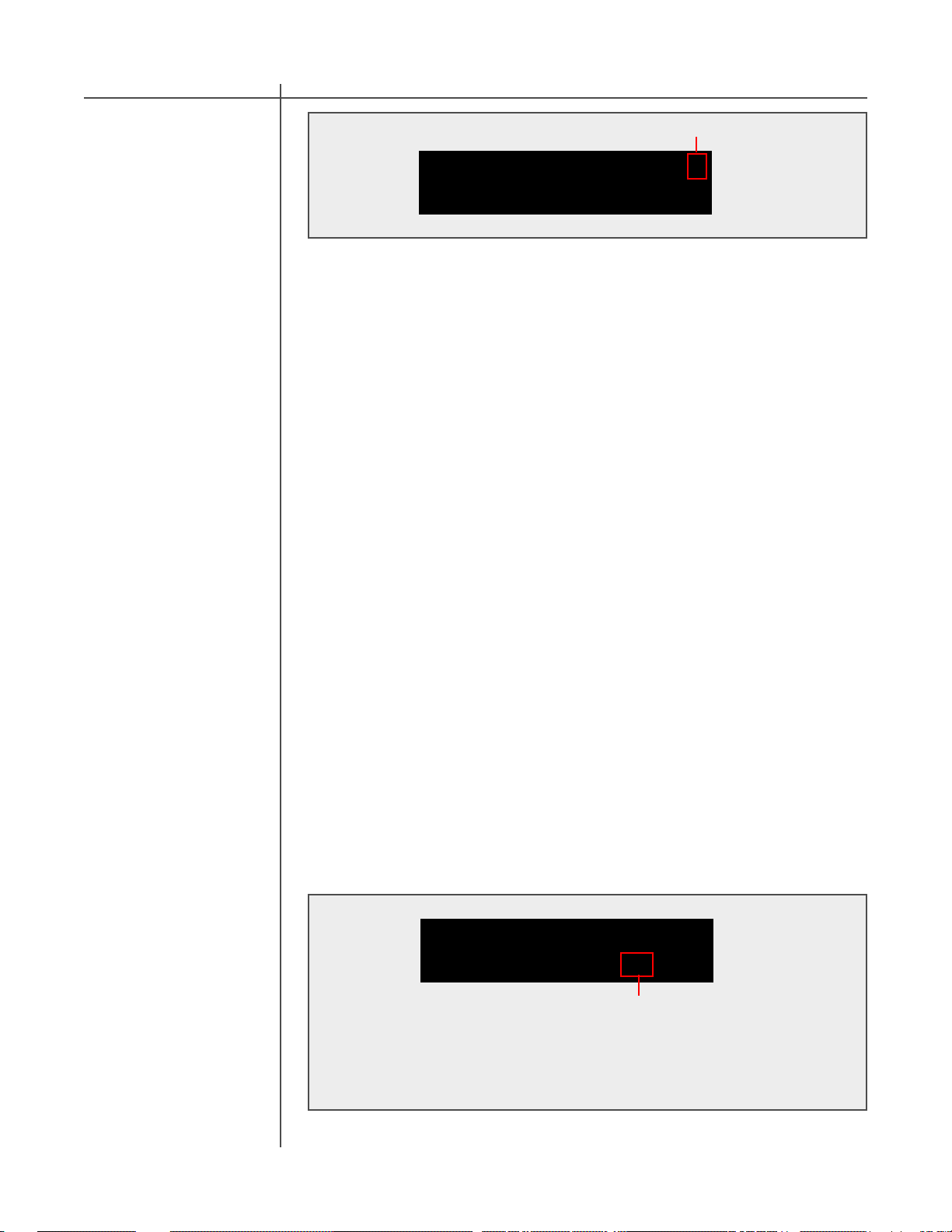
Main menu :
Setup menu option
CAUTION
Select A Setup
Preset
SETUP LEVEL DELAY
ADLY POL APOL->
Press the “MENU” remote control button. This will change the TCS mkII display to the Main menu screen. Then use the “LEFT” and “RIGHT” navigational
buttons to move the selection cursor to select the “SETUP” option. To enter
the menu selection press the “ENTER” button. This will open the SETUP
menu.
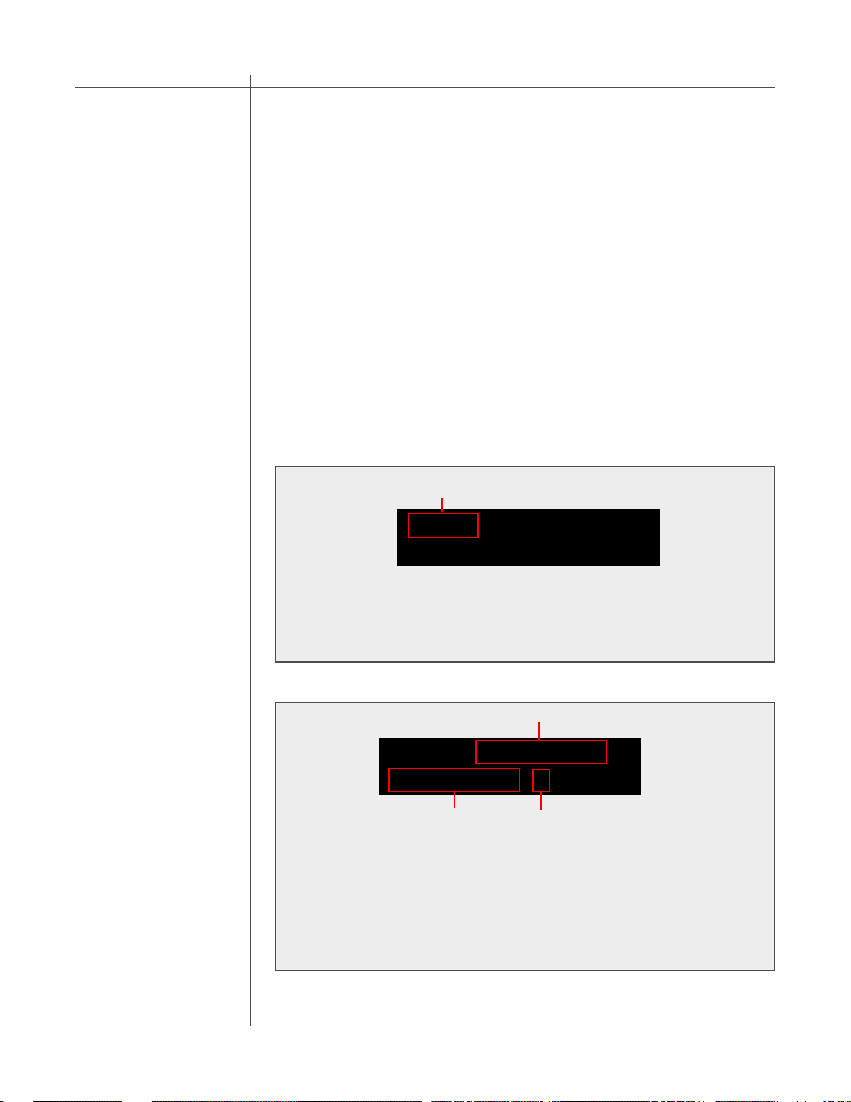
Setup menu :
Active Preset
SETUP : 5. TACT 1 L
5. TACT 1 : SP CRO
SelectorPreset
This example illustrates selecting the “5. TACT 1” preset. To select a preset
move the selection cursor with the “LEFT” and “RIGHT” remote control buttons
to select the “:” preset selector. Use the “UP” and “DOWN” remote control
buttons to select “5. T ACT 1“. The presets will scroll in the Preset section of the
setup menu in sequential order. To activate the “5. TACT 1“ preset press the
“ENTER” button. The preset should now be displayed in the active preset portion
of the screen. Press the “MENU” remote control button two times to return to the
Main Status Screen.
16 T act Audio
Page 17
Getting Started
Step 4:
Step four illustrates the basic operation of the TCS mkII by briefly explaining how to
select an input source, set the correction to “BP” bypass mode, and adjust the
master volume. Please remember to set your unit to bypass “BP” correction mode.
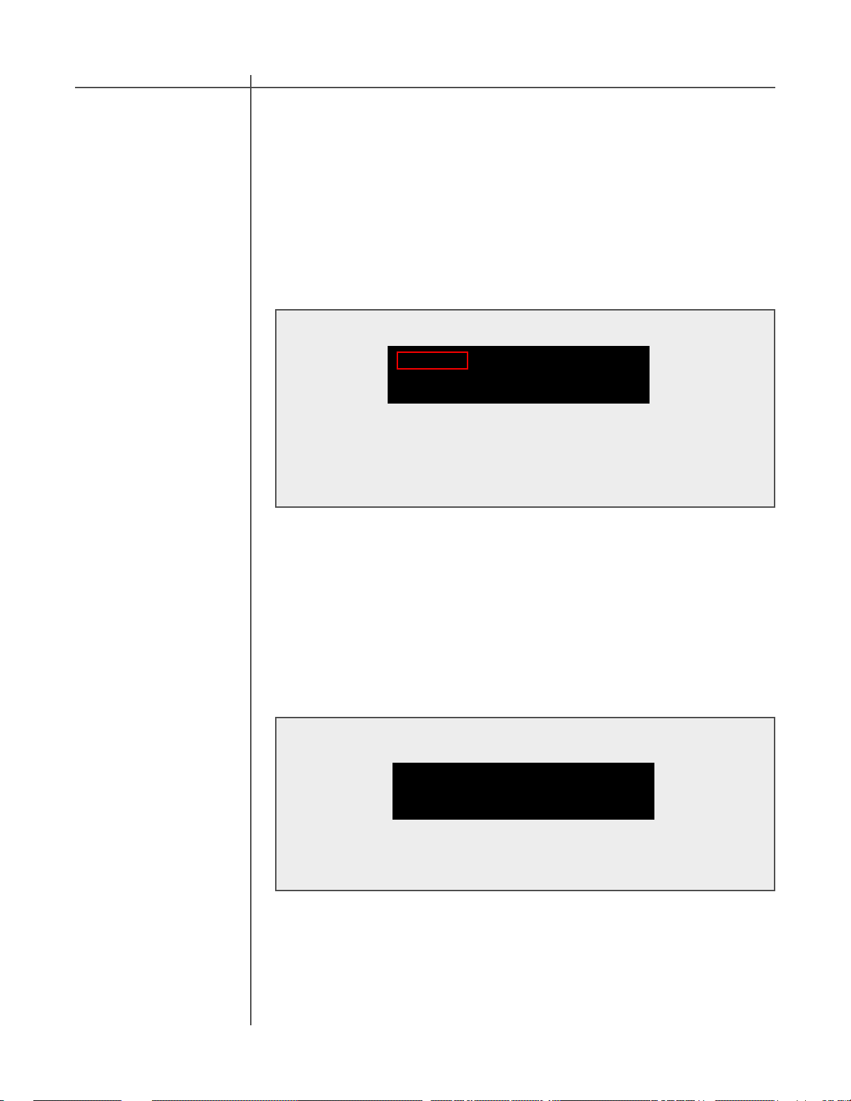
Main Screen :
2
3/2 LFE D1 44.1
Cor:BP S:1 -33.1dB
1
Set your TCS mkII to correction BYP ASS mode (1)
The TCS mk II can be set to bypass mode at any time by pressing the
“BYP ASS” key found in the CORRECTION block on the remote control. When
BYP ASS is enabled “BP” will be displayed on the TCS mkII front panel display.
Selecting an ANALOG or DIGITAL input (2)
T o select an input for playback use the “ANALOG” and “DIGITAL” buttons
found on the remote control. Select the source that you have connected.
- Press the “DIGITAL” button to scroll sequentially to select one of 9
digital inputs.
3
Step 5:
Discovering More
- Press the “ANALOG” button to scroll sequentially to select one of 7
analog inputs.
Setup Preset (3)
The Setup preset should be set to “S:1” or “S:5”. If the setup preset is not set
to one of these presets please review STEP 3.
Adjusting the master volume level
T o adjust master level use the “UP” and “DOWN” volume buttons found on the
remote control or by simply turning the Tact wheel on the TCS mkII front panel.
The output can be muted at any time by pressing remote control “MUTE”
button.
Y ou are now ready to play some audio and enjoy your TCS mkII. You now are
familiar with the basic functionality of the TCS mkII.
The TCS mkII is an extremely versatile system that can be used in many different
hardware configurations. The getting started section is designed to let you start to
get enjoyment from your TCS mkII immediately . This brief section only begins to
explore the many features that the TCS mkII is capable of. We suggest that, over
time, you become familiar with all of the TCS mkII features discussed in this
manual and install the Theatre Correction Software. The Theater Correction
software will allow you to take a room measurement and calculate room correction
curves for your TCS mkII. The sound of the TCS will become even more accurate
after employing the latest version of the world renowned Tact Room Correction.
The TCS mkII combines both state of the art hardware and software to bring you
the ultimate in multichannel audio reproduction.
17T act Audio
Page 18
Front Panel Display
The main status screen is displayed when the TCS mkII is powered on. The main
screen displays the current operating status for the TCS mkII.
Main Status
Screen
Main Screen :
12 3
3/2 LFE D1 44.1
CAUTION
4
Cor:BP S:1 -33.1dB
5
1 - Signal Mode Indicator
2 - LFE Indicator
3 - Active Input Indicator
4 - Digital Input Frequency Indicator
5 - Active Correction Indicator
6 - Active Setup Indicator
7 - Master level in dB
1 - Signal Mode Indicator
The TCS mkII will auto detect the digital signal being sent to the selected input and
display the type of digital signal in the signal mode indicator display . An explanation
of the status labels are listed bellow . STEREO will be displayed when an analog input
is selected unless stereo processing “STP” has been enabled (Dolby Pro Logic II or
DTS Neo:6)
DTS - Multichannel dts signal
6
7
18 T act Audio
STEREO - T wo channel stereo signal
PLII - Dolby Pro Logic II processing enabled
Neo:6 - DTS Neo:6 processing enabled
6 CH. SACD/DVD-A - Digital input D9 selected for the Tact TCS ADC 6 (Sold
Separately)
Dolby Digital - signals are represented in the display where the first number
represents the number of front channels and the second number represents the
number of rear channels present in the decoded signal. This will change according
to the source content that you are currently playing. For example “3/2” would
represent 3 front channels left, center, and right and 2 rear channels lef t rear , and
right rear.
2 - LFE Indicator
The LFE indicator indicates whether or not a low frequency channel is present in the
signal that is being decoded. When “LFE” is displayed the signal being decoded
contains a low frequency channel. If “LFE” is not displayed there is not a low
frequency channel available in the source content that is being decoded.
Page 19

Front Panel Display
3 - Active Input Indicator
The active input indicator displays the active input selected. To change the active
input press the “DIGITAL” or “ANALOG” buttons found on your remote control to
select the input source you would like to listen to. The “DIGITAL” or “ANALOG”
buttons on your remote control are toggle buttons, and by pressing them multiple
times it will toggle through all seven analog and nine digital inputs.
4 - Digital Input Frequency Indicator
The Digital Input Frequency Indicator displays the sampling frequency of the selected
digital input. The TCS mkII will automatically detect digital input signal presence and
display its sampling frequency .
5 - Active Correction Indicator
The active correction indicator displays the active correction you have selected. To
select one of the nine correction presets, or bypass them, press one of the ten
buttons located in the block labeled “CORRECTION” on the remote control.
6 - Active Setup Indicator
The active setup indicator displays the active setup preset. The TCS mkII has thirty
setup presets. The SETUP preset defines the unit’s output channels, signal routing,
and bass management configuration. These parameters are set by using the
controller found in the “SETUP” menu for each output channel. This feature allows for
maximum control over the configuration of the unit. The Setup selection and creation
will be explained in full detail later in the manual.
7 - Master level in dB
This displays the master volume level in dB.
19T act Audio
Page 20
Front Panel Display
Main Menu
The Main menu of the TCS mkII has four pages of general menu selections.
Below is an example of these four pages. From these general menu selections all
of the TCS mkII features can be accessed and edited. To exit back to the Main
Screen press the “MENU” button on the remote control until the Main Menu screen
appears.
CAUTION
Main menu :
SETUP LEVEL DELAY
ADLY POL APOL->
<- TEST LINK TRIG
DISPL PLII STP->
<-DRC ADC AMP
OUTFS LRCRO LFCRO->
Saving Menu
Settings
<- ADDR POWER LOCK
OPT VER
To enter the Menu selection pages press the “MENU” button. Use the “LEFT”
and “RIGHT” navigational buttons to highlight an option with the selection cursor and to proceed to a new page. To enter a highlighted option press the
“ENTER” button. To exit back to the Main Screen press the “MENU” button on
the remote control until the Main Menu screen appears.
Custom settings that are made to any of the menu selections are saved by placing
the TCS mkII into standby mode. If you make changes to any of the menu items and
turn the unit off (by using the main power switch on the front of the unit or
disconnecting the AC power) before placing the unit into st andby mode all settings
will be lost. To save your settings place the TCS mkII into standby mode by pressing
the red “ST ANDBY ” button on the remote control.
20 T act Audio
Page 21
Front Panel Display
Setup Menu
Enter the
Setup Menu
The Setup menu gives you complete control over the TCS mk II. This menu controls
the unit’s output channels, signal routing, and bass management configuration. It is
necessary to select a setup preset to define the configuration of the TCS mkII. This
section will guide you through the Setup menu screens illustrating how to select a
preset and edit custom preset configurations. A tutorial illustrating the setup editing
process step by step appears later in this manual.
Main menu :
SETUP LEVEL DELAY
ADLY POL APOL->
Press the “MENU” button on the remote control to open the main menu
screen. Select the “SETUP” menu option using the “LEFT” and “RIGHT”
navigational buttons and press the “ENTER” button to open the Setup main
menu screen.
The Setup Menu
The Setup Menu displays the active setup preset, allows for preset selection, and
gives access to the Speaker setup and Crossover menus for all ten output channels.
Below is an example of the main Setup Menu display .
Setup menu :
SETUP : 5. TACT 1 L
5. TACT 1 : SP CRO
Setup Menu display .
21T act Audio
Page 22
Front Panel Display
Setup Indicator
Preset Selector
The Setup indicator displays the preset configuration that is currently loaded in the
TCS mkII. One Setup preset is always active as it defines the configuration of the
TCS mkII. This is not a selectable option.
Setup menu :
CAUTION
Setup Indicator
SETUP : 5. TACT 1 L
5. TACT 1 : SP CRO
In this example preset “5. T ACT 1” is the active Setup preset.
The TCS mkII offers thirty setup presets to provide thirty different configuration
selections. There are eight predefined and twenty-two user programmable presets to
choose from. There is always a setup preset active to define the output configuration
of the TCS mkII. You will need to create custom definitions for presets nine through
thirty before they can be used as a custom user configurations.
Select A
Setup Preset
Setup menu :
SETUP : 6. TACT 2 L
5. TACT 1 : SP CRO
SelectorPreset
In this example preset “5. TACT 1” has been selected by scrolling with the
preset selector. To make your selection active press the “ENTER” button. Once
active, the selected preset will appear in the Setup Indicator section
This example illustrates selecting the “5. T ACT 1“ preset. To select a preset move the
selection cursor with the “LEFT” and “RIGHT” remote control buttons to select the “:”
preset selector. Use the “UP” and “DOWN” remote control buttons to select
“5. TACT 1“. The presets will scroll in the Preset section of the setup menu in
sequential order. T o activate the “ 5. T ACT 1“ preset press the “ENTER” button. A fter
you have made your selection the Main Status screen should display “S:5” in the
Setup Indicator section.
22 T act Audio
Page 23
Front Panel Display
Preset Link
Speaker Setup
(SP) Menu
Setup menu :
Link Indicator
SETUP : 5. TACT 1 L
5. TACT 1 : SP CRO
The TCS mkII allows for any one of the thirty Setup configuration presets to be linked
to a Correction preset. This allows for both a Setup configuration and Correction
preset to be activated with a press of a correction preset button. To link a Setup
preset to a Correction preset you must enter the LINK menu from the main menu
section. This is explained later in the Link section of the manual.
The Speaker Setup menu gives complete control over the unit’s output channels,
signal routing, and bass management configuration. In order to fully configure the
TCS mkII from the front panel you will only have to understand two concepts,
OUTPUT Channels and AUDIO Channels. After understanding the difference
between these two concepts you will be able to configure your TCS to match almost
any surround system configuration.
OUTPUT Channels:
The TCS has ten output channels. These are the physical output connectors found
on the back of the unit. You will find that there are different types of connections
available for these outputs but that there are only a total of ten available output
channels.
- 10 output channels: L, R, SL, SR, CEN, LFE, AUX 1, AUX 2, AUX 3, AUX 4
Enter The Speaker
Setup(SP) Menu
AUDIO Channels:
The TCS can playback up to eight decoded audio channels. These are the audio
channels found in your playback source content. This content could be as simple as
a stereo signal from a CD or as complex as a DVD that contains a DTS ES
soundtrack that contains eight discrete channels.
- 8 audio channels: L, R, SL, SR, CEN, LFE, SCL, SCR
Setup menu :
SETUP : 5. TACT 1 L
5. TACT 1 : SP CRO
SP menu
The Speaker Setup (SP) menu is entered from the Setup menu. To enter the
speaker setup menu use the “LEFT” and “RIGHT” remote control buttons to
highlight “SP” and press the “ENTER” button.
23T act Audio
Page 24

Front Panel Display
Output Channels
ON/OFF
Output Channel
Settings
The Speaker menu allows you to turn each of the ten output channels of the TCS mkII
on or off. When a channel is set to “OFF” there will be no output heard from the
corresponding output jack on the back of the TCS mkII even if the source material
contains a signal for this channel.
T o select an output channel use the “ LEFT” and “RIGHT” remote control buttons to
move the selection cursor to the channel that you want to turn on or off. There are two
front panel display pages that display all ten output channels. Then use the “UP” and
“DOWN” remote control buttons to toggle between the “ON” and “OFF” selections in
the channel state section.
Below are examples of common settings for different output configurations.
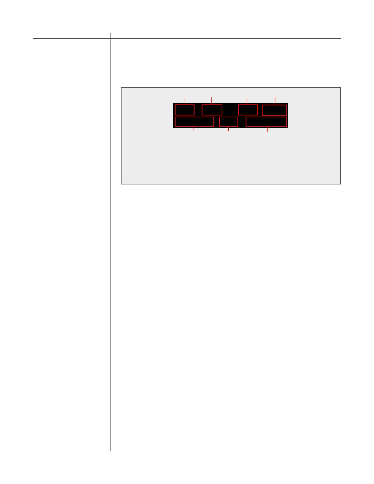
SP menu :
Output Channels
L R SL SR CEN->
ON ON ON ON ON
<-LFE A1 A2 A3 A4
Channel state
10 channel output:
This example displays the settings for ten output channels. The L, R, SL, SR,
CEN, LFE, A1, A2, A3, A4 channels are set to ON for a total of ten output
channels.
ON ON ON ON ON
CAUTION
Channel state
Output Channels
24 T act Audio
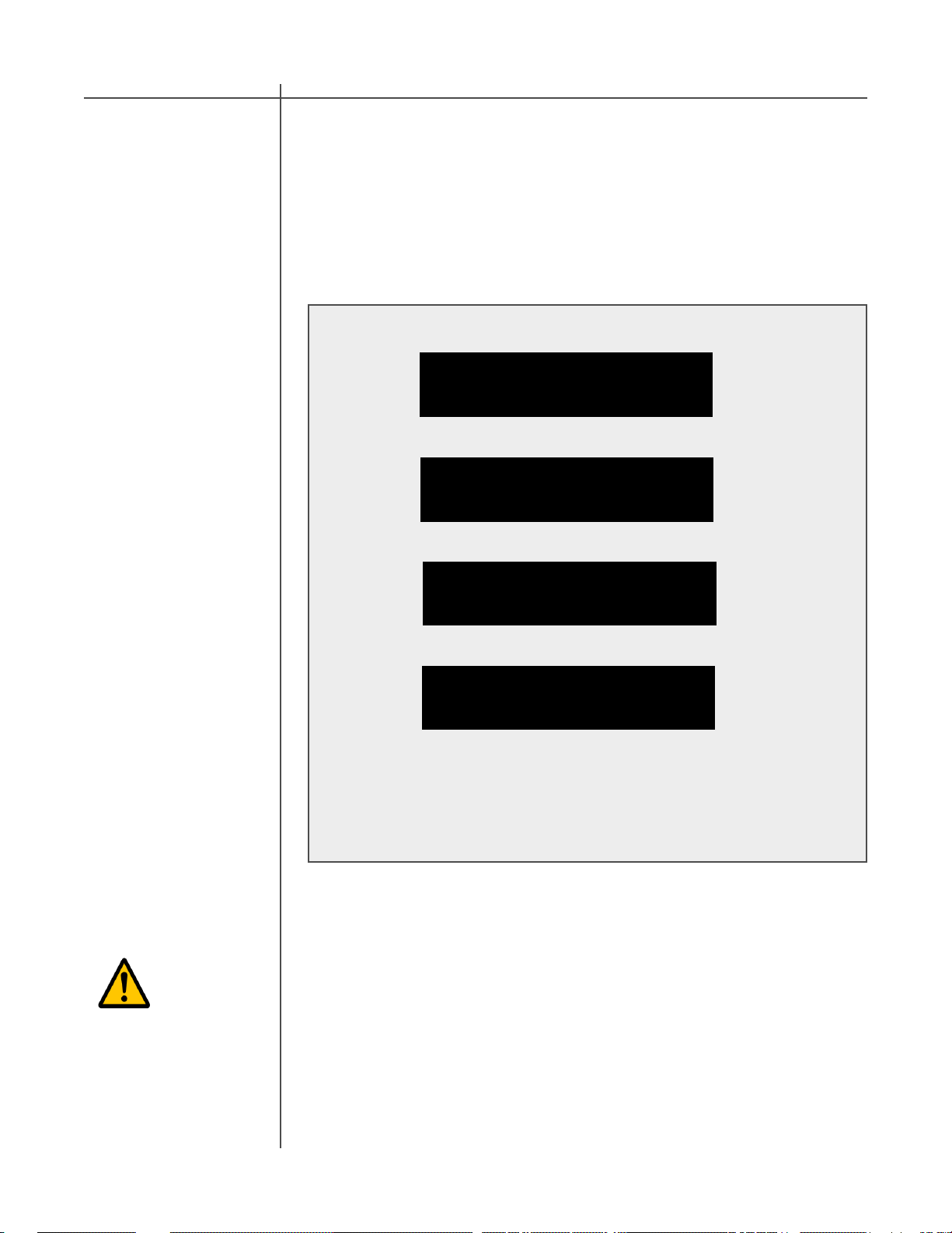
SP menu :
Output Channels
Channel state
2 channel output (stereo):
This example displays the settings for two output channels. The L and R
channels are set to ON and the SL, SR, CEN, LFE, A, A2, A3, A4 channels are
set to OFF for a total of two output channels.
SP menu :
Output Channels
Channel state
6 channel output (5.1):
This example displays the settings for six output channels. The L, R, SL, SR,
CEN, LFE channels are set to ON and the A1, A2, A3, A4 channels are set to
OFF for a total of six output channels.
L R SL SR CEN->
ON ON OFF OFF OFF
<-LFE A1 A2 A3 A4
OFF OFF OFF OFF OFF
L R SL SR CEN->
ON ON ON ON ON
<-LFE A1 A2 A3 A4
ON OFF OFF OFF OFF
Channel state
Output Channels
Channel state
Output Channels
Page 25

Front Panel Display
Audio Channel
Mixer
Enter The
Audio Channel
Mixer
The TCS mk II decodes up to eight audio channels (LEFT, RIGHT , SL, SR, CEN, LFE,
SCL, SCR). Audio channels are the playback content from your source material.
Each audio channel can be controlled with the TCS mkII audio channel mixer . The
Audio Channel mixer is used to set the audio channel level, output channel, and bass
management settings.
Each Output channel can contain all or part of each audio channel that is decoded by
the TCS. For example you may have small speakers and may want to send all of the
low frequency audio from all channels to the LFE output to your subwoofer and send
your other speakers only the high frequency signals. The Audio Channel mixer
allows for this level of control for each of the ten TCS mk II outputs.
SP menu :
Output Channels
L R SL SR CEN->
ON ON ON ON ON
<-LFE A1 A2 A3 A4
Output Channels
ON ON ON ON ON
The Audio
Channel Mixer
T o select an Output channel use the “LEFT ” and “RIGHT” remote control buttons
to move the selection cursor to the output channel you would like to edit. Press
the “ENTER” button to open the Audio Channel Mixer menu screen for the
selected output.
After selecting the output channel the Audio Channel mixer for the selected output
will open.
LFE Audio Channel Mixer :
TCS mk II Output Audio Channel
LFE :LEFT CRO
0.0 dB OFF ->
Audio Channel Level
In this example the LFE output LEFT audio channel mixer is displayed. This
mixer screen would be used to send the LEFT audio channel signal to the LFE
output channel. From this screen you can turn the LEFT audio channel off or on,
set the level in dB, and apply a highpass or lowpass crossover for sending it to
the LFE output.
Audio Channel Crossover
25T act Audio
Page 26

Front Panel Display
Audio Channel
Mixer
There are eight audio channel mixers for each of the ten TCS mkII outputs. Each of
the eight audio channels can be assigned and combined to output from any of the 10
output channels of the TCS mkII. Use the “LEFT” and “RIGHT” remote control
buttons to scroll through each of the eight audio channels available for the selected
TCS mkII output channel. The eight audio channel mixers are displayed over eight
front panel display pages.
CAUTION
Below is an example of the eight audio channel mixer screens available
for the LFE output channel. This set of eight audio channel mixers is
available for each of the ten TCS mkII outputs. Below is a key defining
each output abbreviation.
LFE Audio Channel Mixer :
TCS mk II Output Audio Channel
LFE :LEFT CRO
0.0 dB OFF ->
Audio Channel Level Audio Channel Crossover
LFE :LEFT CRO
0.0 dB OFF ->
<-LFE :CEN CRO
0.0 dB OFF ->
<-LFE :RIGHT CRO
0.0 dB OFF ->
<-LFE :SL CRO
0.0 dB OFF ->
<-LFE :SR CRO
0.0 dB OFF ->
Audio channel key:
LEFT - left audio channel CEN - center audio channel
RIGHT - right audio channel LFE - LFE audio channel
SL - surround left audio channel A1 - surround center left audio ch.
SR - surround right audio channel A2 - surround center right audio ch.
<-LFE :LFE CRO
0.0 dB OFF ->
<-LFE :SCL CRO
0.0 dB OFF ->
<-LFE :SCR CRO
0.0 dB OFF
26 T act Audio
Page 27

Front Panel Display
Audio Channel
Mixer Level
Set An
Audio Channel
Level
Audio Channel Level:
Each audio channel has a level that is set in dB. This defines the volume of the
selected audio channel that you want to appear at the selected Output of the TCS
mkII.
For example: You may want to send all of the eight audio channels to the LFE
output channel of the TCS mkII. This would allow for all low frequencies to be
handled from the LFE output for the subwoofer instead of using the seven main
speakers. The example below illustrates setting the level for each of the LFE audio
channels.
Level setting LFE TCS output:
Below is an example of the eight audio channel mixer screens available for the
LFE output channel. The levels for the Left, Right, Center , Surround L, Surround
R, Surround Center L, and Surround Center R audio channels are set to -15dB.
This will send output from each audio channel at -15dB to the LFE output
subwoofer. The LFE audio channel is set to -5dB. The decrease in dB is
suggested so as not to overdrive the LFE channel after summing all audio
channels.
LFE Audio Channel Mixer :
TCS mk II Output Audio Channel
LFE :LEFT CRO
0.0 dB OFF ->
Audio Channel Level Audio Channel Crossover
LFE :LEFT CRO
-15.0 dB LP ->
<-LFE :RIGHT CRO
-15.0 dB LP ->
<-LFE :SL CRO
-15.0 dB LP ->
<-LFE :SR CRO
-15.0 dB LP ->
T o select an audio channel use the “LEFT” and “RIGHT” remote control buttons
to move the selection cursor to the audio channel you would like to edit. The
audio channel level indicator displays the level for the audio channel displayed
by the Audio Channel indicator. This parameter allows you to turn the audio
channel off or define its volume level in dB. This sets the level that the audio
channel will appear at the selected TCS mk II output. Press the “ENTER” button
to toggle the audio channel on or off selection. The display will show “OFF” for no
output and “x.xxdB” when on. To change the volume level use the “UP” and
“Down” remote control buttons to scroll through the settings in .01 dB steps.
<-LFE :CEN CRO
-15.0 dB LP ->
<-LFE :LFE CRO
- 5.0 dB OFF ->
<-LFE :SCL CRO
-15.0 dB LP ->
<-LFE :SCR CRO
-15.0 dB LP
27T act Audio
Page 28

Front Panel Display
Audio Channel
Mixer Crossover
Set An
Audio Channel
Crossover
A highpass or lowpass crossover is available for each audio channel. This parameter
allows for a highpass or lowpass crossover to be set for the selected audio channel at
the selected Output of the TCS mkII.
For example:Y ou may want to send all of the eight audio channels to the LFE output
channel of the TCS mkII. This would allow for all low frequencies to be handled from
the LFE output for the subwoofer instead of using the seven main speakers. The
example below illustrates the crossover “CRO” settings for each of the LFE audio
channels.
NOTE: Bass management (LP and HP crossovers) applied from the Setup
menu should only be used when the unit is in theater correction BYPASS
mode “CRO:BP”.
NOTE: When using ROOM CORRECTION use the audio channel mixer to route
the audio channel signals to the desired output channels and set their levels
only. The theater correction software will then be used to set crossover
points with a much greater frequency range for the LFE, AUX3, and AUX4
output channels and allow for correction curves with bass roll off for all other
channels. This provides for more powerful bass management from the T act
Theater correction processor.
Crossover setting LFE TCS output:
Below are the eight audio channel mixer screens available for the LFE output
channel. The crossovers for the Left, Right, Center, Surround L, Surround R,
Surround Center L, and Surround Center R channels are set to LP(lowpass filter)
to have the low frequencies from these audio channels to be sent to the LFE
output subwoofer. The LFE audio channel is set to OFF so that no filtering is
applied to this channel.
LFE Audio Channel Mixer :
CAUTION
28 T act Audio
TCS mk II Output Audio Channel
LFE :LEFT CRO
0.0 dB OFF ->
Audio Channel Level Audio Channel Crossover
LFE :LEFT CRO
-15.0 dB LP ->
<-LFE :RIGHT CRO
-15.0 dB LP ->
<-LFE :SL CRO
-15.0 dB LP ->
<-LFE :SR CRO
-15.0 dB LP ->
To assign a crossover setting use the “UP” and “Down” remote control buttons
to scroll through the OFF, LP or HP options.
<-LFE :CEN CRO
-15.0 dB LP ->
<-LFE :LFE CRO
- 5.0 dB OFF ->
<-LFE :SCL CRO
-15.0 dB LP ->
<-LFE :SCR CRO
-15.0 dB LP
Page 29

Front Panel Display
CRO Menu The CRO menu sets the crossover point (frequency) for the highpass and lowpass
filters that are applied in the Audio Channel Mixer menu. The crossover point can be
set from 50Hz to 150Hz in 5Hz steps. Crossover points can be set independently for
each of the eight audio channels.
NOTE: Bass management (LP and HP crossovers) applied from the Setup
menu should only be used when the unit is in theater correction BYPASS
mode “CRO:BP”.
NOTE: When using ROOM CORRECTION use the audio channel mixer to route
the audio channel signals to the desired output channels and set their levels
only. The theater correction software will then be used to set crossover
points with a much greater frequency range for the LFE, AUX3, and AUX4
output channels and allow for correction curves with bass roll off for all other
channels. This provides for more powerful bass management from the T act
Theater correction processor.
Enter The
CRO Menu
Set A Crossover
Frequency
Setup menu :
SETUP : 5. TACT 1 L
5. TACT 1 : SP CRO
CRO Menu
The Crossover (CRO) menu is entered from the Setup menu. To enter the
crossover menu use the “LEFT” and “RIGHT” remote control buttons to highlight
“CRO” and press the “ENTER” button.
CRO menu :
Output Channels
L R SL SR ->
80 80 80 80 Hz
Crossover Frequency
Output Channels
CEN LFE A1 A2
<-80 80 80 80 Hz
Crossover Frequency
To select an Output Channel use the “LEFT” and “RIGHT” remote control
buttons to select the channel then use the “UP” and “Down” buttons to scroll
through the frequency values in 5Hz steps.
29T act Audio
Page 30

Front Panel Display
Level Menu
Enter The
LEVEL Menu
The level menu controls the system output channel balancing. Y ou can adjust the
systems output balance by changing the attenuation for any of the ten output
channels. An independent set of audio channel level settings can be set for each of
the ten room correction presets. If you find that there is no need to balance the
system level, these screens should be set to all zeroes (maximum signal level is at
0.0 dB).
NOTE: These settings are automatically adjusted in theater correction
mode. We strongly recommend that you only adjust these settings for correction bypass mode - this will allow you to match the settings with correction mode for A/B comparison.
Main menu :
CAUTION
SETUP LEVEL DELAY
ADLY POL APOL->
Press the menu button on the remote control to open the main menu screen.
Select the “LEVEL” menu option using the “LEFT” and “RIGHT” navigational
buttons and press the “ENTER” button to open the Level display screen.
Channel Level
30 T act Audio
Set The
LEVEL menu :
Output Channels
Active Correction Preset
LEFT RIGHT CR:1
0.0 0.0 dB ->
Output Level
LEFT RIGHT CR:1
0.0 0.0 dB ->
<- CEN LFE CR:1
0.0 0.0 dB ->
AUX3 AUX4 CR:1
<- 0.0 0.0 dB
T o select an output channel to edit use the “LEFT” and “RIGHT” remote
control buttons to select the output channel then use the “UP” and “Down”
buttons to scroll through the settings in .1 dB steps. To select a different
correction preset press one of the ten correction preset buttons to activate the
correction preset for editing.
<-SURL SURR CR:1
0.0 0.0 dB ->
<- AUX1 AUX2 CR:1
0.0 0.0 dB ->
Page 31

Front Panel Display
Delay Menu
Enter The
DELA Y Menu
The Delay menu is used to time align the system loudspeakers. Delay times can
be adjusted on all ten channels in increments of about 10 microseconds (0.00 TO
42.65 MSEC). An independent set of audio channel delay settings can be set for
each of the ten room correction presets.
NOTE: These settings are automatically adjusted in theater correction
mode. We strongly recommend that you only adjust these settings for correction bypass mode - this will allow you to match the settings with correction mode for A/B comparison.
Main menu :
SETUP LEVEL DELAY
ADLY POL APOL->
Press the “MENU” button on the remote control to open the main menu
screen. Select the “DELAY” menu option using the “LEFT” and “RIGHT”
navigational buttons and press the “ENTER” button to open the Delay display
screen.
Set The
Channel Delay
DELAY menu :
Output Channels
Active Correction Preset
LEFT RIGHT CR:1
0.00 0.00 msec->
Output Delay Time
LEFT RIGHT CR:1
0.00 0.00 msec->
<- CEN LFE CR:1
0.00 0.00 msec->
AUX3 AUX4 CR:1
<- 0.00 0.00 msec
T o select an output channel to edit use the “LEFT” and “RIGHT” remote
control buttons to select the channel then use the “UP” and “Down” buttons to
scroll through the settings in .01 msec steps. To edit a different correction
preset press one of the ten correction preset buttons to activate a new preset
for editing.
<-SURL SURR CR:1
0.00 0.00 msec->
<-AUX1 AUX2 CR:1
0.00 0.00 msec->
31T act Audio
Page 32

Front Panel Display
ADLY menu
Enter The
ADL Y Menu
The Absolute Delay menu provides delay that is applied globally to all ten output
channels . An independent delay setting can be set for each of the ten room
correction presets.
NOTE: The purpose of this option is to more closely match the movie dialog
to the displayed picture, as some video processors introduce a slight delay
in delivering the video because of video processing time requirements.
Main menu :
CAUTION
SETUP LEVEL DELAY
ADLY POL APOL->
Press the “MENU” button on the remote control to open the main menu
screen. Select the “ADLY” menu option using the “LEFT” and “RIGHT”
navigational buttons and press the “ENTER” button to open the Absolute Delay
display screen.
Set The
Absolute
Delay
ADLY menu :
Active Correction Preset
C0R1:Absolute Delay
0.00 msec
Output Delay Time
T o edit the absolute delay use the “UP” and “DOWN” remote control buttons to
change the delay setting in increments of .01 ms. To edit a different correction
preset press one of the ten correction preset buttons to activate the correction
preset for editing.
32 T act Audio
Page 33

Front Panel Display
POL Menu
Enter The
POL Menu
Set The
Channel
Polarity
The polarity menu allows for individual phase control for all ten output channels . An
independent set of polarity settings can be set for each of the ten room correction
presets. When “POL+” is selected for a channel, the output signal is in phase with
the input signal. When “POL-“ is selected, the output signal is out of phase –
shifted 180 degrees with respect to the input signal.
Main menu :
SETUP LEVEL DELAY
ADLY POL APOL->
Press the “MENU” button on the remote control to open the main menu
screen. Select the “POL” menu option using the “LEFT” and “RIGHT”
navigational buttons and press the “ENTER” button to open the Polarity display
screen.
POL menu :
Output Channels
Active Correction Preset
LEFT RIGHT CR:1
POL+ POL+ ->
Output Level
LEFT RIGHT CR:1
POL+ POL+ ->
<-CEN LFE CR:1
POL+ POL+ ->
AUX3 AUX4 CR:1
<-POL+ POL+
T o select an output channel use the “LEFT” and “RIGHT” remote control
buttons to select the channel then use the “UP” and “DOWN” buttons to toggle
the POL+ and POL- selections. To edit a different correction preset press one
of the ten correction preset buttons to activate the correction preset for editing.
<-SURL SURR CR:1
POL+ POL+ ->
<- AUX1 AUX2 CR:1
POL+ POL+ ->
33T act Audio
Page 34

Front Panel Display
APOL menu
Enter The
APOL Menu
The absolute polarity menu provides a phase setting that is applied globally to all
ten output channels . An independent absolute polarity setting can be set for each
of the ten room correction presets. Positive “+” is the default setting and is the
normal operating mode for the TCS mkII. When Negative “-“ is selected all output
polarity settings are flipped. For example if you have channels that were set to “-”
they will now be “+” and all “+” will be set to “-”.
Main menu :
CAUTION
SETUP LEVEL DELAY
ADLY POL APOL->
Press the “MENU” button on the remote control to open the main menu
screen. Select the “APOL” menu option using the “LEFT” and “RIGHT”
navigational buttons and press the “ENTER” button to open the Absolute
Polarity display screen.
34 T act Audio
Set The
Absolute
Polarity
APOL menu :
Active Correction Preset
Active Polarity Setting
C0R1:Absolute POL:+
+ -
Polarity Selections
T o edit the absolute polarity use the “LEFT” and “RIGHT” remote control
buttons to select either the “+” or “-“ setting and then press the “ENTER”
button to activate your selection. The active selection will be displayed in the
active polarity setting section. To edit a different correction preset press one
of the ten correction preset buttons to activate the correction preset for editing.
Page 35

Front Panel Display
TEST menu
Enter The
TEST Menu
The test menu provides a basic system check by producing a white noise signal to
verify signal presence independently on all ten output channels.
Main menu :
<- TEST LINK TRIG
DISPL PLII STP->
Press the “MENU” button on the remote control to open the main menu
screen. Select the “TEST” menu option using the “LEFT” and “RIGHT”
navigational buttons and press the “ENTER” button to open the Test display
screen.
Playing A
T est Tone
TEST menu :
Channel Test ->
L R SL SR CEN
Output Channels
<- Channel Test
LFE A1 A2 A3 A4
Output Channels
T o test an output channel use the “LEFT” and “RIGHT” remote control
buttons to select a channel and then press and hold down the “ENTER”
button. This will produce white noise at the output of a selected channel while
the “ENTER” button is held.
35T act Audio
Page 36

Front Panel Display
LINK menu
Enter the
Link Menu
Create a Link
The TCS mkII allows for any one of the thirty Setup configuration presets to be linked
(assigned) to a Correction preset. This allows for both a Setup configuration and
Correction preset to be activated with a press of a correction preset button.
For example: You can link Setup preset “5” to Room Correction preset “1”. Now
when Room Correction “1” is selected it will automatically activate Setup preset “5”
no matter what Setup preset was previously set.
Main menu :
CAUTION
<- TEST LINK TRIG
DISPL PLII STP->
Press the “MENU” button on the remote control to open the main menu
screen. Select the “LINK” menu option using the “LEFT” and “RIGHT”
navigational buttons and press the “ENTER” button to open the Link display
screen.
Link menu :
Correction Selection Setup Selection
CORR 1 TO SETUP 1
CORR SETUP 5
Correction Selector Setup Selector
Link a preset example: Link Correction 1 to Setup 5
This example will illustrate how to link Room Correction preset 1 to Setup preset
5. When finished, whenever Room Correction preset 1 is selected Setup 5 will
be activated.
Use the “LEFT” and “RIGHT” remote control buttons to select “CORR” and use
the “UP” and “Down” buttons to select “CORR 1”. This is the Room
Correction preset selector. The nine available correction presets will scroll in
sequential order. The correction preset selected will be displayed in the
correction selection.
Now use the “LEFT” and “RIGHT” remote control buttons to select “SETUP”
and use the “UP” and “Down” buttons to select “SETUP 5”. This is the Setup
preset selector. There are 30 setup presets and “--” (no link) that will scroll in
sequential order.
When you have found the “SETUP 5” preset press the “ENTER” button to
activate your selection. The active selection will be displayed in the Setup
Selection section.
36 T act Audio
NOTE: To have no link for the correction preset select the “--” selection. While
selecting a preset it will be displayed in the Setup Selector window.
Page 37

Front Panel Display
TRIG menu
Enter The
TRIG Menu
The Trigger menu allows you to assign events on the TCS mkII that will produce a
12 volt signal at each of the two trigger outputs. Event triggers can be assigned to
any of the ten correction presets, or “XXX” - always on, and “---” - off.
For example: You can set a trigger to activate when you select your favorite room
correction preset used for watching movies. This would allow for a projection screen
with a trigger input to lower automatically when the correction preset is selected.
Main menu :
<- TEST LINK TRIG
DISPL PLII STP->
Press the “MENU” button on the remote control to open the main menu
screen. Select the “TRIG” menu option using the “LEFT” and “RIGHT”
navigational buttons and press the “ENTER” button to open the Trigger display
screen.
Set A Trigger
TRIG menu :
Active Trigger Setting
T1: XXX T2:-- XXX ---
Trigger Selector
T o assign an event to a trigger use the “LEFT” and “RIGHT” remote control
buttons to select trigger output “T1” or “T2” then use the “UP” and “Down”
buttons to scroll through the trigger event options. When you have found the
event that you want to assign press the “ENTER” button to activate your
selection.
37T act Audio
Page 38

Front Panel Display
DISPL menu
Enter The
DISPL Menu
The Display menu is used to enable or disable the front panel display time-out
option. When the display time-out is activated “ON”, the display will turn off after
approximately 10 seconds of inactivity from the remote or the Tact volume wheel. If
the display time-out is set to “OFF”, the display will always remain lit.
CAUTION
Main menu :
<- TEST LINK TRIG
DISPL PLII STP->
Press the “MENU” button on the remote control to open the main menu
screen. Select the “DISPL” menu option using the “LEFT” and “RIGHT”
navigational buttons and press the “ENTER” button to open the Display menu
screen.
DISPL Timeout
38 T act Audio
Setting A
DISPL menu :
Active Timeout Setting
Display Timeout: OFF
OFF ON
Timeout Selector
T o set the display timeout mode use the “LEFT” and “RIGHT” remote control
buttons to select the “ON” or “OFF” options and press the “ENTER” button to
activate the selected option.
Page 39

Front Panel Display
PLII menu
Enter The
PLII Menu
The PLII menu is used to select the type of Dolby Pro Logic® II processing you
would like apply when Dolby Pro Logic® II processing is enabled from the “STP”
menu option. The TCS mkII offers Dolby Pro Logic® II Music, Movie, Matrix, and
Music Panorama modes. These modes offer different channel mixing and
processing designed to work best with various types of two channel content.
Select the mode that best matches your content or yields the best multichannel
sound from your two channel source material.
Note: Pro Logic® II processing is not enabled from this menu. To enable
the Pro Logic® II processing you must turn it on from the “STP” menu op-
tion.
Main menu :
<- TEST LINK TRIG
DISPL PLII STP->
Press the “MENU” button on the remote control to open the main menu
screen. Select the “PLII” menu option using the “LEFT” and “RIGHT”
navigational buttons and press the “ENTER” button to open the PLII display
screen.
Setting The
PLII Mode
PLII menu :
Active PLII Mode
PLII Mode: Music
PL Mu Mv Mtx MuP
PLII Mode Selections
PL - Pro Logic
Mu - Music
Mv - Movie
Mtx - Matrix
MuP - Music Panorama
T o set the PLII processing mode use the “LEFT” and “RIGHT” remote control
buttons to select the mode then press the “ENTER” button to activate your
selection. The active PLII mode is displayed in the active PLII mode section of
the screen.
39T act Audio
Page 40

Front Panel Display
STP menu
Enter The
STP Menu
The Stereo Processing menu is used to enable DTS® Neo:6 or Dolby® Pro
Logic® II processing. DTS® Neo:6 provides up to six channels of matrix decoding
from stereo matrix material and expands stereo non-matrix recordings into six
channels. Dolby® Pro Logic® II provides up to five channels of matrix decoding
from stereo matrix material and expands stereo non-matrix recordings into five
channels. Only one processing mode can be enabled at a time. For example if
you have selected Dolby Pro Logic® II to “ON” and then select DTS® Neo:6 to
“ON” Dolby® Pro Logic® II will be automaticly set to “OFF”.
Main menu :
CAUTION
<- TEST LINK TRIG
DISPL PLII STP->
Press the “MENU” button on the remote control to open the main menu
screen. Select the “STP” menu option using the “LEFT” and “RIGHT”
navigational buttons and press the “ENTER” button to open the Stereo
Processing display screen.
40 T act Audio
Setting The
STP State
STP menu :
Active PL II Setting Active NEO:6 Setting
PL II-OFF Neo:6-ON
OFF ON OFF ON
PL II On/OFF Selector NEO:6 On/Off Selector
T o assign S tereo Processing use the “LEFT” and “RIGHT” remote control
buttons to select an “ON” or “OFF” option for PL II or Neo:6 then press the
“ENTER” button to activate your selection. The active processing selection will
show in the main display screen after being selected.
Page 41

Front Panel Display
DRC menu
Enter The
DRC Menu
The DRC menu enables or disables the Dynamic Range Compression available in
Dolby Digital source material. Some Dolby Digital DVD and CDs have DRC
encoded audio tracks that will respond to the DRC option when enabled. If the
DRC menu is set to HALF or FULL the dynamic levels in the source material will
be limited. The “HALF” setting will apply 50% of the “FULL” compression setting.
If set to “OFF” the system will playback source material at its full dynamic range.
For example: You may want to set the DRC control to “FULL” for late night movie
viewing. By setting the DRC control to “FULL” the volume level of loud content
such as explosions will be compressed to the volume level of the softer content
such as the dialog.
Main menu :
<-DRC ADC AMP
OUTFS LRCRO LFCRO->
Set The
DRC Mode
Press the “MENU” button on the remote control to open the main menu
screen. Select the “DRC” menu option using the “LEFT” and “RIGHT”
navigational buttons and press the “ENTER” button to open the Dynamic
Range Compression display screen.
DRC menu :
Active DRC Setting
DRC: OFF
OFF HALF FULL
DRC Selector
To select a DRC setting use the “LEFT” and “RIGHT” remote control buttons to
select the “OFF”, “HALF”, or “FULL” selection and then press the “ENTER”
button to activate your selection. The active state is displayed in the active DRC
settings section.
41T act Audio
Page 42

Front Panel Display
ADC menu
Enter The
ADC Menu
The TCS mkII is equipped with a state of the art Analog to Digital Converter . T o further
enhance the converter’s performance, the system offers independent “NORMAL”
(-6dB) or “HIGH” (0dB) selectable gain values for the ADC input st age for each of the
seven analog inputs.
NORMAL: -6dB in reference to 0.0dB. Input sensitivity: 2.2 volt.
HIGH : 0dB in reference to 0.0dB. Input sensitivity: 4.4 volt.
Main menu :
CAUTION
<-DRC ADC AMP
OUTFS LRCRO LFCRO->
Press the “MENU” button on the remote control to open the main menu
screen. Select the “ADC” menu option using the “LEFT” and “RIGHT”
navigational buttons and press the “ENTER” button to open the Analog to
Digital Converter display screen.
42 T act Audio
Set The
ADC Mode
ADC menu :
Active ADC SettingActive Input
ADC Gain In 1:Normal
NORMAL HIGH
DRC Selector
To select a gain setting use the “LEFT” and “RIGHT” remote control buttons to
select the “NORMAL” or “HIGH” selection and then press the “ENTER” button to
activate your selection. To select a different input press the “ANALOG” button on
the remote control to scroll through the seven analog inputs.
Page 43

Front Panel Display
AMP menu
Enter The
AMP Menu
The AMP menu allows the TCS mkII to be set to interface with the Tact M2150 and
S2150 digital amplifiers. With the TCS mkII you can control multiple digital
amplifiers. The default amplifier setting for all outputs is “Disabled”.
NOTE: The amplifier settings are stored as part of the active “SETUP” preset. Any changes made to the “AMP” settings will be retained for the active “SETUP” preset. This gives a total of 30 different AMP configurations
that can be stored. If you create a new setup you will need to set the AMP
configuration to match your amplifiers that are connected.
NOTE: When a Tact digital amplifier is controlled by the TCS mkII, all of the
amplifiers front panel and IR controls are disabled. Use the RS232 port and/
or daisy chain to link the components.
CAUTION: The AMP setting should only be set to ENABLED if you have Tact
amplifiers connected to the TCS mkII. When the AMP option is set to ENABLED both the analog and digital output will send a full level signal regardless of the TCS mkII master volume setting. If you do not have Tact amplifiers
connected to your system you will not be able to control the output level
from the TCS mkII volume control. The output is sent at its maximum level
and can result in damage to your speakers.
Main menu :
Set The
AMP Mode
<-DRC ADC AMP
OUTFS LRCRO LFCRO->
Press the “MENU” button on the remote control to open the main menu
screen. Select the “AMP” menu option using the “LEFT” and “RIGHT”
navigational buttons and press the “ENTER” button to open the Amplifier display screen.
AMP menu :
Digital Output
L R SL SR CEN->
En En En En En
Active Amplifier Setting
Digital Output
<-LFE A1 A2 A3 A4
En En En En En
Active Amplifier Setting
To change the AMP menu settings use the “LEFT” and “RIGHT” remote control buttons to select the output channel you would like to edit. Then press
the “ENTER” button to toggle the “En” and “Dis” settings.
43T act Audio
Page 44

Front Panel Display
OUTFS menu
Enter The
OUTFS Menu
Set The
OUTFS
The TCS mkII is equipped with a sample rate converter for each digital output.
Each output can independently be set to 44.1, 48, 88, 96 and 192 kHz sampling
frequencies.
Main menu :
CAUTION
<-DRC ADC AMP
OUTFS LRCRO LFCRO->
Press the “MENU” button on the remote control to open the main menu
screen. Select the “OUTFS” menu option using the “LEFT” and “RIGHT”
navigational buttons and press the “ENTER” button to open the OUTFS display
screen.
OUTFS menu :
Digital Output
Active Output Sample Frequency
Left/Right :96.0 K
44 48 88 96 192
Sample Frequency Selection
Left/Right :96.0 K
44 48 88 96 192
Cen/LFE :96.0 K
44 48 88 96 192
AUX3/AUX4 :96.0 K
44 48 88 96 192
To select the a digital output to edit use the “UP” and “DOWN” remote control
buttons to scroll through the output selections. To select a sampling frequency
use the “LEFT” and “RIGHT” buttons and press the “ENTER” button to activate
your selection.
Sur L/R :96.0 K
44 48 88 96 192
AUX1/AUX2 :96.0 K
44 48 88 96 192
44 T act Audio
Page 45

Front Panel Display
LRCRO menu
Enter The
LRCRO Menu
The Left/Right Crossover menu offers five crossover selections for use with the Left
and Right output channels while in correction bypass mode. This will set the crossover point for the Left and AUX3(lef t sub) output channels and the Right and
AUX4(right sub) output channels. The Left/Right bypass crossover filters are user
programmable from the Crossover screen in the Theatre Correction Software.
Crossovers in correction mode are implemented into the correction filter via the
Theater Correction Software.
NOTE: These settings are automatically adjusted in theater correction
mode. We strongly recommend that you only adjust these settings for correction bypass mode - this will allow you to match the settings with correction mode for A/B comparison.
Main menu :
<-DRC ADC AMP
OUTFS LRCRO LFCRO->
Press the “MENU” button on the remote control to open the main menu
screen. Select the “LRCRO” menu option using the “LEFT” and “RIGHT”
navigational buttons and press the “ENTER” button to open the Left/Right
Crossover display screen.
Set The
LRCRO
LRCRO menu :
Active Crossover
LRCRO: None
1. None *
Crossover Selector Active Indicator
To select a crossover use the “UP” and “DOWN” remote control buttons. To
activate your selection press the “ENTER” button. The active crossover will be
displayed in the active crossover section of the screen and an astrict is displayed after the active crossover in the selection list.
45T act Audio
Page 46

Front Panel Display
LFCRO menu
Enter The
LFCRO Menu
The LFE Crossover menu offers five crossover selections for the LFE output channel for use when in correction bypass mode only . The LFE bypass crossover filters
are user programmable from the Crossover screen in the Theatre Correction Software. Crossovers in correction mode are implemented into the correction filter via
the Theater Correction Software.
CAUTION
NOTE: These settings are automatically adjusted in theater correction
mode. We strongly recommend that you only adjust these settings for correction bypass mode - this will allow you to match the settings with correction mode for A/B comparison.
Main menu :
<-DRC ADC AMP
OUTFS LRCRO LFCRO->
Press the “MENU” button on the remote control to open the main menu
screen. Select the “LFCRO” menu option using the “LEFT” and “RIGHT”
navigational buttons and press the “ENTER” button to open the LFE Crossover
display screen.
46 T act Audio
Set The
LFCRO
LFCRO menu :
Active Crossover
LRCRO: None
1. None *
Crossover Selector Active indicator
To select a crossover use the “UP” and “DOWN” remote control buttons. To
activate your selection press the “ENTER” button. The active crossover will be
displayed in the active crossover section of the screen and an astrict is displayed after the active crossover in the selection list.
Page 47

Front Panel Display
ADDR menu
Enter The
ADDR Menu
Set The
TCS ADDR
The Address menu allows for setting the TCS system’s exclusive address. A
unique system address is needed to communicate with external devices such as
your computer running the TCS software.
Main menu :
<- ADDR POWER LOCK
OPT VER
Press the “MENU” button on the remote control to open the main menu
screen. Select the “ADDR” menu option using the “LEFT” and “RIGHT”
navigational buttons and press the “ENTER” button to open the Address
display screen.
ADDR menu :
Active Address
RS232 Address: 1
Address: 1
Address Selector
To change the system device address value use the “UP” and “DOWN” navigational buttons to select the desired system address and then press the
“ENTER” button to select it. The active address will be displayed in the active
address section of the screen. The TCS mkII is shipped with the default address set at 1.
NOTE: If you change the device address make sure that you select the appropriate device address in the TCS mkII Theater Correction software.
47T act Audio
Page 48

Front Panel Display
POWER
menu
Enter The
POWER Menu
The Power menu allows the user to decide what power state the TCS mkII will be in
after pressing the front power button. The TCS mkII can be set to power up fully or
to start in standby mode.
CAUTION
Main menu :
<- ADDR POWER LOCK
OPT VER
Press the “MENU” button on the remote control to open the main menu
screen. Select the “POWER” menu option using the “LEFT” and “RIGHT”
navigational buttons and press the “ENTER” button to open the Power display
screen.
48 T act Audio
Set The
Power State
POWER menu :
Active Power State
Power ON : STANDBY
ON STANDBY
Power State Selections
To change the power on state use the “LEFT” and “RIGHT” navigational buttons to select the desired setting “ON” or “STANDBY” and then press the
“ENTER” button to select it. The active power state will be displayed in the active power state section of the screen.
Page 49

Front Panel Display
LOCK menu
Enter The
LOCK Menu
The Lock menu allows a lock to be set to prevent entering any of the TCS mk II editing menus without unlocking them with the lock code. By default the TCS mk II is
unlocked and all menus can be accessed without entering the lock code. When
the unit is locked, the only menu option that can be entered is the “LOCK” menu to
unlock the unit. Once the lock code is entered you will be able to use the TCS mk
II menus until the the lock code is entered again.
Main menu :
<- ADDR POWER LOCK
OPT VER
Press the “MENU” button on the remote control to open the main menu
screen. Select the “LOCK” menu option using the “LEFT” and “RIGHT”
navigational buttons and press the “ENTER” button to open the Lock display
screen.
Set The
LOCK Code
LOCK menu :
Active Lock State
TCS MKII : LOCKED
PASSWORD : 0000 SET
Lock Code
To lock or unlock the TCS mk II enter the lock code “1-2-3-4” by using the
“LEFT” and “RIGHT” remote control buttons to highlight each digit and use the
“UP” and “DOWN” buttons to select the desired number from 0 to 9 . Once the
code is entered select the “SET” option and press the “ENTER” button to unlock or lock the TCS mkII menus. The active lock state will be displayed in
the active lock state portion of the screen.
Set Button
49T act Audio
Page 50

Front Panel Display
OPT menu
The Option menu allows for setting the TCS mk II volume wheel sensitivity , maximum volume level, and increased output gain.
Max Level:
The “Max Level” option controls the systems maximum signal level. For example,
if this option is set to -3.0 dB, the volume control can not go above -3.0 dB.
CAUTION
Wheel:
The “Wheel” option sets the “TacT Wheel” volume control sensitivity. The wheel
sensitivity can be set to between “1” and “10” or to “OFF” to disable the Wheel for
volume control. The lower the setting the slower the volume increases and the
higher the setting the faster the volume increases with each turn of the Wheel.
Gain:
The “Gain” option allows for an increase in the overall volume level of the TCS.
There are four gain settings that are available: 0dB, 6dB, 12dB, and 18dB. The
method for which the gain will be applied is determined by the “ENABLED” or “DIS-
ABLED” amplifier setting in the “AMP” menu.
Disabled Amplifiers:
When one or more outputs have their amplifier setting set to disabled, all increased gain for these outputs will be applied at the TCS mkII outputs. The
TCS mkII will increase its overall gain by the amount set in the “Gain” setting.
For example if “0dB” is selected the TCS will output +0dB at maximum volume, if “18dB” is selected the TCS mkII will output +18dB at maximum volume.
50 T act Audio
Enabled Amplifiers:
When one or more outputs have their amplifier setting set to “ENABLED” all increased gain for these outputs will be applied at the 2150’s output. The TCS
mk II will output a full level signal no matter what the TCS mkII volume is set
to. The 2150 amplifier will increase its overall gain by the amount set in the
“Gain” setting on the TCS mkII. The TCS mkII’s volume display will reflect the
change in dB but all increased gain will be applied at the amplifiers. For example if “0dB” is selected, the TCS will output at full level and the 2150 will
output at +0dB at maximum volume, if “18dB” is selected the TCS will output
at full level and the 2150 will output at +18dB at maximum volume.
Page 51

Front Panel Display
Enter The
OPT Menu
Setting The
OPT Settings
Main menu :
<- ADDR POWER LOCK
OPT VER
Press the “MENU” button on the remote control to open the main menu
screen. Select the “OPT” menu option using the “LEFT” and “RIGHT” naviga-
tional buttons and press the “ENTER” button to open the OPT display screen.
OPT menu :
Max Level Wheel Gain
0.0 dB 5 12dB
Max Level
Setting
To edit the “Max Level” setting use the “LEFT” and “RIGHT” remote control
buttons to select the “Max Level” selector and use the “UP” and “DOWN” buttons to select the desired output level setting in dB.
To edit the “Wheel” sensitivity setting use the “LEFT” and “RIGHT” remote
control buttons to select the “Wheel” selector and use the “UP” and “DOWN”
buttons to select the desired wheel sensitivity setting in increments of 1
through 10, and OFF to disable the wheel for volume control.
To edit the “Gain” setting use the “LEFT” and “RIGHT” remote control buttons
to select the “Gain” selector and use the “UP” and “DOWN” buttons to select
the desired gain level setting 0dB, 6dB, 12dB, and 18dB.
Wheel Setting
Gain Level
Setting
51T act Audio
Page 52

Front Panel Display
VER menu
Enter The
VER Display
The Version screen displays the product name and the version of the firmware
currently installed on the TCS mkII.
Main menu :
CAUTION
<- ADDR POWER LOCK
OPT VER
Press the “MENU” button on the remote control to open the main menu
screen. Select the “VER” menu option using the “LEFT” and “RIGHT”
navigational buttons and press the “ENTER” button to open the Version display
screen.
The VER
Display
Version display:
TCS Model
TCS MKII
Version: 012803 V1.0
Firmware Version
To exit the Info screen press the “MENU” button to return to the TCS mkII main
menu.
52 T act Audio
Page 53

TCS mkII Theater Correction Software
The TCS mkII employs some of the most advanced audio software ever developed.
In order to use the Tact Theater Correction System, you have to install the supplied
software on your computer . Complete instructions for using the room correction
software can be found in the online help available in the software.
System requirements
Software Installation
Start The Room
Correction software
Y our computer system must meet the following requirements:
- An IBM compatible PC with Pentium 100 MHz, 64 MB Ram & 100 MB
free hard disk space or better
- Microsoft Windows 98, ME, 2000 or XP
- Operating system regional setting must be set to “English(United St ates)”
- Microsoft Windows-compatible graphics-card and monitor with screen
resolution 800x600 or better
- CD-ROM drive
- Microsoft windows compatible 2- or 3- button mouse
- Standard RS-232 serial port with DB-9 connectors
Follow the steps below to install the TCS mkII Theater Correction Software:
1 - S tart windows and insert the Tact software CD into your CD-ROM drive.
2 - Double-click on the “My Computer” icon on the desktop.
3 - Double-click on the CD icon to launch the CD browser .
4 - Double-click on “Install TCS mkII vx.x.exe” and follow the instructions.
After the installation you will have the option to launch the TCS mkII software. If
you would like to launch the program at this time when prompted, select “Launch
T act-TCS mkII” and the software will st art. You should now see the TCS mkII Theater Correction System main-screen.
T o st art the software go to the Windows “Start” menu, select “Programs” then
“T ACT Audio” and click on the “TCS mkII” icon. Y ou should now see the Tact-TCS
mkII Theater Correction System main screen.
Microphone
Installation
All Tact measurement microphones are individually calibrated to perform with the
highest accuracy and come with a unique calibration file. This file needs to be
installed before you perform the correction process. The microphone can be enabled or disabled by clicking on the “mic:” display window found on the main
screen with your left mouse button to toggle its setting.
1 - Insert the Tact software disc into the computer’s CD-ROM drive.
2 - S tart the Tact-TCS mkII Correction System Software on your computer.
3 - Select “File” from the menu selection at the top of the main software screen.
4 - Select “Microphone” and a new window will open.
5 - Select your CD-Rom drive in the “Look-in” menu, you should now see a file in
the larger window below.
6 - Select the “Micxxxxx.mic” file. The number in the file name should match the
serial number of the mic that came with your Tact-TCS mkII.
7 - The software installation will confirm with the “Mic installation complete”
message.
8 - After you have inst alled your mic the mic serial number should be displayed in
the “Microphone” section at the top of the main page. If it is not please close
the software and then restart it to register the microphone file with the software.
53T act Audio
Page 54

TCS mkII Theater Correction Software
Connect your
TCS mkII to your
Computer
Y our TCS mkII must be connected to your computer’s serial port in order for it to
communicate with your computer and to run the theater correction process.
Please follow the steps below to connect your TCS mkII to your computer .
1 - Make sure that your TCS mkII is turned off using the master power switch on
the back of the unit.
2 - Connect the RS 232 “Input” jack on the back of the TCS mkII to your
computer’s serial port using the supplied cables and adapters. Y our
computer must have a standard RS 232 serial port with a DB 9 connector .
3 - Turn on your TCS mkII.
4 - If your computer is not on, turn it on and start the Tact-TCS mkII Theater
Correction System Software.
5 - Select the “Com” button on the main software screen to open the
communication window.
6 - Under the Operating Mode select “Connect”.
7 - Under the COM Port section select “COM1”. If you receive an “invalid
port number” message please try selecting each of the port selections until
you do not receive this message. If you receive this message on all COM ports
you may not have a COM port installed on your computer . Please refer to your
computer manufacture’s documentation for help to install a COM port.
CAUTION
8 - To verify that TCS mkII is properly connected to the host computer click on the
“Start” button to perform the communication test. If everything is functioning
properly you should see the results below . Press the “Stop” button af ter about
15 seconds to stop the test.
Rx Buf should display “0”.
Count should have counted in increments of “1”.
Err Count should be “0”.
If the results are as above select the “Close” button to close the
communication window. Your TCS mkII is now connected to your computer.
If the results are not as above please go back to step number 6 and select
another COM port. Then repeat step 7.
NOTE: If you are still are not passing the communication test you may not
have a COM port installed on your computer or you may have another device such as a modem or hand held PC that may be sharing the COM port
on your computer. If you have a Tact amplifier attached it may be set to the
same address. The TCS mkII requires a valid COM port that is not being
used by any other devices.
NOTE: You will only have to select the communication port once. The next
time you run the TCS mkII correction software it will remember your settings.
54 T act Audio
Page 55

Setup Presets
The TCS mkII offers thirty setup presets to provide thirty different configuration
selections. There are eight predefined and twenty two user programmable presets to
choose from.
The eight predefined presets are detailed in this section. They are split into two
categories “Dolby” and “T act”.
The Dolby presets apply bass management filtering to the audio channels to filter
both high and low frequencies. This is the traditional method of filtering the bass with
the internal decoder as used by most home theater decoders.
The Tact presets do not apply bass management filtering and are designed to work in
conjunction with the Tact Theater Correction software. If you select one of the four
predefined Tact setup presets without assigning a correction preset that contains
crossover assignments and correction curves that contain bass roll off there will be no
bass management applied to the decoded signals. The bass management that is
applied with the Tact Theater Correction software is more powerful than the filters
provided within the TCS mkII’s processing decoder. It is highly recommended that
you use the TCS mkII in this manner to create a more stunning theater experience.
We highly recommend that you only use the internal decoders for bass filtering when
performing A/B comparisons af ter performing theater correction.
1. Dolby 1 (SSS1)
In this configuration all main channels are filtered at 100Hz and all frequencies
below 100 Hz are sent to the LFE subwoofer. Dolby refers to this output
configuration as SSS1. This preset should be selected if you have smaller
speakers and would like all lower frequencies handled by the LFE subwoofer. The
TCS frequency response in SSS1 output configuration is shown below.
L, C, R, LS, RS, RCS
LFE in Sub Out
L, C, R, LS, RS, RCS in Sub Out
55T act Audio
Page 56

Setup Presets
2. Dolby 2 (LSS0)
In this configuration the Left and Right channels are not filtered, the center and
surround channels are filtered at 100 Hz and the LFE subwoofer is set to OFF .
Dolby refers to this output configuration as LSS0. Select this preset if your system
contains two large main front speakers with both small center and surrounds
without an LFE subwoofer. All low frequencies will be filtered to the front lef t and
right speakers. The TCS frequency response in LSS0 output configuration is
shown in below.
CAUTION
LFE in L, R
C, LS, RS, RCS
L, R
C, LS, RS, RCS in L & R
3. Dolby 3 (LSL0)
In this configuration the Left and Right channel are not filtered, the center channel
is filtered at 100Hz, and the surround channels are not filtered and the subwoofer is
set to OFF. Dolby refers to this output configuration as LSL0. Select this preset if
you have large right and left front speakers and surround speakers, a small center
channel and no LFE subwoofer. The center channel low frequencies and the LFE
channel are filtered to the front left and right speakers. The TCS frequency
response in LSL0 output configuration is shown below.
56 T act Audio
L, R, LS, RS, RCS
C
C in L & R
LFE IN L & R
Page 57

Setup Presets
4. Dolby 4 (L000)
In this configuration the Left and Right channels are not filtered, and the Center,
Surround channels, and the LFE subwoofer are set to OFF . Dolby refers to this
output configuration as L000. Select this preset if you have large left and right front
speakers only and would like to have all channels filtered to the front left and right
channels. TCS frequency response in L000 output configuration is shown in below .
L, R
C, LS, RS, RCS in L & R
LFE in L & R
1. Tact 1 (LLL1)
The Tact 1 setup configuration is designed for a system with large speakers in all
positions with an LFE subwoofer.
The “T act 1” output configuration does not apply any bass management filtering to
the signals coming out from the surround decoder. All signals coming out from the
surround sound decoder are full range with their maximum levels. This setup is
designed to be used with either the TCS theater correction processing (for bass
management) or in theater correction bypass mode if your system has large
speakers in all positions and does not require any bass management..
L, R, C, LS, RS, RCS
LFE
57T act Audio
Page 58

Setup Presets
2. Tact 2 (SSS1)
The Tact 2 setup configuration is designed for a system with small speakers in all
positions with an LFE subwoofer. In this configuration the setup preset is set to
send all main channels a full range signal, and the LFE subwoofer is sent a full
range signal from all audio channels. This setup is designed to be used with the
TCS theater correction processing. All necessary filtering should be implemented
using TCS mkII theater correction processor .
The “T act 2” output configuration does not apply any filtering to signals coming out
CAUTION
from the surround decoder. However , in this configuration all main channels are
directed to the subwoofer output with -15.0 dB of attenuation. This setup is very
similar to Dolby output configuration 1 after theater correction with crossover points
is applied.
L, R, C, LS, RS, RCS
L, R, C, LS, RS, RCS in Sub Out
LFE in Sub Out
58 T act Audio
Page 59

Setup Presets
Tact 3 Configuration (STEREO)
The Tact 3 setup configuration is designed for a system with Left and Right
speakers only . The Surround, Center , Surround Center , and SUB outputs are set
to OFF . The Tact 3 output configuration is designed for stereo output and it should
be used only with the TCS mkII theater correction processor . All necessary
filtering should be implemented using TCS mkII theater correction processor . In
this configuration only Left and Right channel are output with 0.0 dB of attenuation
and with full range. TCS frequency response in Tact 3 output configuration is
shown below.
L, R
Tact 4 Configuration (STEREO)
The Tact 4 setup configuration is designed for a system with Left, Right, and LFE
Subwoofer speakers only . The Surround, Center , and Surround Center channels
are set to OFF. The T act 4 setup configuration is designed for stereo output and
it should be used only with the TCS mkII room correction processor . All
necessary filtering should be implemented using TCS mkII theater correction
processor. In this configuration the Lef t and Right channels are output with 0.0
dB of attenuation and with full range. The Left and Right channel are also
attenuated by –6.0 dB and passed to the LFE Subwoofer output. TCS frequency
response for the T act 4 setup configuration is shown below .
L, R
L & R in Sub Out
59T act Audio
Page 60

Setup Tutorial
T o help give a complete underst anding of the Setup menu option for the TCS mkII we
have created a tutorial to demonstrate how to configure a TCS mkII setup. This
tutorial will illustrate creating an eight channel setup that will send all low frequency
signals to the LFE channel subwoofer and filter the high frequency signals to the
seven main channel speakers. This setup would be commonly known as setting your
main speakers to small so that they will not reproduce the low frequencies found in
the source content thereby directing all low frequencies to the LFE output. After
reviewing the tutorial we hope that you will have a complete understanding of the
Setup options and will be able to apply the concepts demonstrated in the tutorial to
your own system setups.
NOTE: If you plan to use theater correction we suggest that you not perform
the instructions for setting crossovers for any of the output channels. Please
use the TCS mkII Theater Correction software to set the crossover points and
correction curves with bass roll off for bass management. In this type of
setup you would use the audio channel mixer to route all audio channels and
set their level. The theater correction software then is used to set the
crossover points and correction curves with bass roll off for more powerful
bass management by using the T act Theater correction processor .
Open the setup menu:
Main menu :
CAUTION
60 T act Audio
SETUP LEVEL DELAY
ADLY POL APOL->
Press the “MENU” button on the remote control to open the main menu
screen. Select the “SETUP” menu option using the “LEFT” and “RIGHT” navigational buttons and press the “ENTER” button to open the Setup main menu
screen.
Select a user preset to edit:
Setup menu :
SETUP : 9. USER 1
9. USER 1 : SP CRO
SelectorPreset
Move the selection cursor with the “LEFT” and “RIGHT” remote control buttons
to select the “:” preset selector. Use the “UP” and “DOWN” remote control
buttons to scroll in sequential order to select the “9. USER 1” preset. Press the
“ENTER” button to activate the “9. USER 1“ preset. The “9. USER 1“ preset
should now appear at the top of the Setup menu screen.
Page 61

Setup Tutorial
Open the Speaker Setup (SP) menu:
Setup menu :
SETUP : 9. TACT 1 L
9. TACT 1 : SP CRO
SP menu
To enter the speaker setup menu use the “LEFT” and “RIGHT” remote control
buttons to highlight “SP” and press the “ENTER” button.
Set the TCS mkII output channels:
SP menu :
Output Channels
Channel state
For our tutorial we want to set the L, R, SL, SR, CEN, LFE, A1, A2 channels to
ON. The A3 and A4 channels should be set to OFF. Following the instructions
below match the Output Channel states shown above in the SP menu.
T o select an output channel use the “LEFT” and “RIGHT” remote control buttons
to move the selection cursor to the channel that you want to turn on or off. Then
use the “UP” and “DOWN” remote control buttons to toggle between the “ON”
and “OFF” selections in the channel state section.
L R SL SR CEN->
ON ON ON ON ON
<-LFE A1 A2 A3 A4
ON ON ON OFF OFF
Channel state
Output Channels
61T act Audio
Page 62

Setup Tutorial
Open the LFE Audio Channel Mixer:
For our tutorial we will start with the LFE audio channel mixer . For this type of
setup it is the channel that will require the most modifications to be made.
SP menu :
CAUTION
L R SL SR CEN->
ON ON ON ON ON
<-LFE A1 A2 A3 A4
ON ON ON ON ON
Use the “LEFT” and “RIGHT” remote control buttons to move the selection
cursor to the LFE output channel. Press the “ENTER” button. The screen
should now display the LFE Audio Channel Mixer menu screen.
LFE Audio Channel Mixer:
LFE Audio Channel Mixer :
TCS mk II Output Audio Channel
LFE :LEFT CRO
0.0 dB OFF ->
Audio Channel Level Audio Channel Crossover
In this example the LFE output Audio Channel mixer for the LEFT audio channel
is displayed. From this screen you can turn the LEFT audio channel off or on,
set its level in dB, and apply a highpass or lowpass crossover.
62 T act Audio
Page 63

Setup Tutorial
Audio Channel Level setting for LFE TCS output:
Each audio channel has a level that is set in dB. This defines the amount of the
selected audio channel that you want to appear at the selected Output of the TCS
mkII. For our tutorial we want to send all of the eight audio channels to the LFE TCS
mkII output channel.
Level Settings LFE Channel TCS output:
Below are the eight audio channel mixer screens available for the LFE output
channel. The levels for the Left, Right, Center , Surround L, Surround R, Surround
Center L, and Surround Center R audio channels need to be set to -15dB. This
will send a signal from each audio channel at -15dB to the TCS mkII LFE output
channel. The LFE audio channel should be set to -5dB as only a small amount
of attenuation is needed for this audio channel to output from the TCS mkII LFE
output channel as normal. Please follow the instructions below to match the
settings in the screens below to match your unit
LFE :LEFT CRO
-15.0 dB LP ->
LFE :RIGHT CRO
-15.0 dB LP ->
LFE :SL CRO
-15.0 dB LP ->
LFE :SR CRO
-15.0 dB LP ->
Use the “LEFT” and “RIGHT” remote control buttons to move the selection
cursor to the level selector shown above. Press the “ENTER” button to toggle
the audio channel ON. The display will show “OFF” for no output and “x.xxdB”
when on. To change the volume level use the “UP” and “Down” remote control
buttons scroll through the settings in .01 dB steps. Please repeat these steps
to set the desired level for each of the audio channels for the LFE output.
LFE :CEN CRO
-15.0 dB LP ->
LFE :LFE CRO
- 5.0 dB OFF ->
LFE :SCL CRO
-15.0 dB LP ->
<-LFE :SCR CRO
-15.0 dB LP
63T act Audio
Page 64

Setup Tutorial
Audio Channel Crossover setting for LFE TCS output:
Each audio channel has a highpass or lowpass crossover. This parameter is the
bass manger control for the TCS mkII. The setting allows for a highpass or lowpass
crossover to be set for the selected audio channel for the selected Output of the TCS
mkII. For this example we want to send all of the eight audio channels to the LFE
channel TCS mkII output to have all low frequencies handled from the output for the
subwoofer instead of using the seven main speakers.
NOTE: If you plan to use theater correction we suggest that you skip this step
and set the crossover point for the LFE channel using the TCS mkII Theater
Correction software. In this type of setup you would use the audio channel
mixer to route all audio channels and set their level. The theater correction
software then is used to set the crossover points and correction curves with
bass roll off for more powerful bass management by using the Tact Theater
correction processor.
Crossover setting LFE TCS output:
Below are the eight audio channel mixer screens available for the LFE output
channel. The crossovers for the Left, Right, Center, Surround L, Surround R,
Surround Center L, and Surround Center R channels are set to LP(lowpass filter)
to have only the low frequencies from these audio channels sent to the TCS mkII
LFE output channel. The LFE audio channel is set to OFF as we do not want
any filtering on this channel so it will output as normal. Please follow the
instructions below to match your settings to the screens above.
CAUTION
LFE :LEFT CRO
-15.0 dB LP ->
LFE :RIGHT CRO
-15.0 dB LP ->
LFE :SL CRO
-15.0 dB LP ->
LFE :SR CRO
-15.0 dB LP ->
Use the “LEFT” and “RIGHT” remote control buttons to move the selection
cursor to the crossover selector shown above. To change the CRO setting use
the “UP” and “Down” remote control buttons to scroll to the desired setting.
Please repeat these steps to set the desired crossover setting for each channel
for each of the audio channels for the LFE output.
LFE :CEN CRO
-15.0 dB LP ->
LFE :LFE CRO
- 5.0 dB OFF ->
LFE :SCL CRO
-15.0 dB LP ->
<-LFE :SCR CRO
-15.0 dB LP
64 T act Audio
Page 65

Setup Tutorial
Audio Mixer setting for the LEFT TCS output:
SP menu :
L R SL SR CEN->
ON ON ON ON ON
<-LFE A1 A2 A3 A4
ON ON ON ON ON
Press the ‘MENU” button to return to the SP menu. Use the “LEFT” and
“RIGHT” remote control buttons to move the selection cursor to the “L” output
channel. Press the “ENTER” button. The screen should now display the “LEFT”
Audio Channel Mixer menu screen.
LEFT Channel TCS output:
Below are the eight audio channel mixer screens available for the TCS mkII LEFT
output channel. All audio channels except for the LEFT are set to off as we only
want the LEFT audio channel appearing at the LEFT TCS mkII output. The LEFT
audio channel also has a highpass filter enabled so that only high frequencies
from the LEFT audio channel are passed to the LEFT TCS mkII output. Please
follow the instructions below to match your settings to the screens below.
LEFT :LEFT CRO
0.0 dB HP ->
LEFT
LEFT :RIGHT CRO
Off OFF ->
LEFT :SL CRO
Off OFF ->
LEFT :SR CRO
Off OFF ->
Set the LEFT channel level:
Use the “LEFT” and “RIGHT” remote control buttons to move the selection
cursor to the level selector . Press the “ENTER” button to toggle the audio
channel ON. The display will show “OFF” for no output and “x.xxdB” when on.
Then use the “UP” and “Down” remote control buttons to set the level to 0.0 dB.
Set the LEFT channel crossover:
Use the “LEFT” and “RIGHT” remote control buttons to move the selection
cursor to the CRO selector . To change the CRO setting use the “UP” and
“Down” remote control buttons to scroll to the desired setting.
LEFT :CEN CRO
Off OFF ->
LEFT :LFE CRO
Off OFF ->
LEFT :SCL CRO
Off OFF ->
<-LEFT :SCR CRO
Off OFF
Please repeat these steps to set the desired level and crossover setting for each
channel for each of the audio channels for the LEFT output.
65T act Audio
Page 66

Setup Tutorial
Audio Mixer setting for the RIGHT TCS output:
SP menu :
L R SL SR CEN->
ON ON ON ON ON
<-LFE A1 A2 A3 A4
CAUTION
ON ON ON ON ON
Press the ‘MENU” button to return to the SP menu. Use the “LEFT” and
“RIGHT” remote control buttons to move the selection cursor to the “R” output
channel. Press the “ENTER” button. The screen should now display the
“RIGHT” Audio Channel Mixer menu screen.
RIGHT Channel TCS output:
Below are the eight audio channel mixer screens available for the TCS mkII
RIGHT output channel. All audio channels except for the RIGHT are set to off as
we only want the RIGHT audio channel appearing at the RIGHT TCS mkII output.
The RIGHT audio channel also has a highpass filter enabled so that only high
frequencies from the RIGHT audio channel are passed to the RIGHT TCS mkII
output. Please follow the instructions below to match your settings to the
screens below.
RIGHT:LEFT CRO
Off OFF ->
RIGHT:RIGHT CRO
0.0 dB HP ->
RIGHT
RIGHT:CEN CRO
Off OFF ->
RIGHT:LFE CRO
Off OFF ->
66 T act Audio
RIGHT:SL CRO
Off OFF ->
RIGHT:SR CRO
Off OFF ->
Set the RIGHT channel level:
Use the “LEFT” and “RIGHT” remote control buttons to move the selection
cursor to the level selector . Press the “ENTER” button to toggle the audio
channel ON. The display will show “OFF” for no output and “x.xxdB” when on.
Then use the “UP” and “Down” remote control buttons to set the level to 0.0 dB.
Set the RIGHT channel crossover:
Use the “LEFT” and “RIGHT” remote control buttons to move the selection
cursor to the CRO selector . To change the CRO setting use the “UP” and
“Down” remote control buttons to scroll to the desired setting.
Please repeat these steps to set the desired level and crossover setting for each
channel for each of the audio channels for the RIGHT output.
RIGHT:SCL CRO
Off OFF ->
<-RIGHT:SCR CRO
Off OFF
Page 67

Setup Tutorial
Audio Mixer setting for the SURROUND LEFT TCS output:
SP menu :
L R SL SR CEN->
ON ON ON ON ON
<-LFE A1 A2 A3 A4
ON ON ON ON ON
Press the ‘MENU” button to return to the SP menu. Use the “LEFT” and
“RIGHT” remote control buttons to move the selection cursor to the “SL” output
channel. Press the “ENTER” button. The screen should now display the
“SURROUND LEFT” Audio Channel Mixer menu screen.
SURROUND LEFT (SL) Channel TCS output:
Below are the eight audio channel mixer screens available for the TCS mkII SL
output channel. All audio channels except for the SL are set to off as we only
want the SL audio channel appearing at the SL TCS mkII output. The SL audio
channel also has a highpass filter enabled so that only high frequencies from the
SL audio channel are passed to the SL TCS mkII output. Please follow the
instructions below to match your settings to the screens below.
SL :LEFT CRO
Off OFF ->
SL :RIGHT CRO
Off OFF ->
SL :SL CRO
0.0 dB HP ->
SL
SL :SR CRO
Off OFF ->
Set the SURROUND LEFT channel level:
Use the “LEFT” and “RIGHT” remote control buttons to move the selection
cursor to the level selector . Press the “ENTER” button to toggle the audio
channel ON. The display will show “OFF” for no output and “x.xxdB” when on.
Then use the “UP” and “Down” remote control buttons to set the level to 0.0 dB.
Set the SURROUND LEFT channel crossover:
Use the “LEFT” and “RIGHT” remote control buttons to move the selection
cursor to the CRO selector . To change the CRO setting use the “UP” and
“Down” remote control buttons to scroll to the desired setting.
SL :CEN CRO
Off OFF ->
SL :LFE CRO
Off OFF ->
SL :SCL CRO
Off OFF ->
<-SL :SCR CRO
Off OFF
Please repeat these steps to set the desired level and crossover setting for each
channel for each of the audio channels for the SURROUND LEFT output.
67T act Audio
Page 68

Setup Tutorial
Audio Mixer setting for the SURROUND RIGHT TCS output:
SP menu :
L R SL SR CEN->
ON ON ON ON ON
<-LFE A1 A2 A3 A4
CAUTION
ON ON ON ON ON
Press the ‘MENU” button to return to the SP menu. Use the “LEFT” and
“RIGHT” remote control buttons to move the selection cursor to the “SR” output
channel. Press the “ENTER” button. The screen should now display the
“SURROUND RIGHT” Audio Channel Mixer menu screen.
SURROUND RIGHT (SR) Channel TCS output:
Below are the eight audio channel mixer screens available for the TCS mkII SR
output channel. All audio channels except for the SR are set to of f as we only
want the SR audio channel appearing at the SR TCS mkII output. The SR audio
channel also has a highpass filter enabled so that only high frequencies from the
SR audio channel are passed to the SR TCS mkII output. Please follow the
instructions below to match your settings to the screens below.
SR :LEFT CRO
0.0 dB OFF ->
SR :RIGHT CRO
Off OFF ->
SR :CEN CRO
Off OFF ->
SR :LFE CRO
Off OFF ->
68 T act Audio
SR :SL CRO
Off OFF ->
SR :SR CRO
SR
0.0 dB HP ->
Set the SURROUND RIGHT channel level:
Use the “LEFT” and “RIGHT” remote control buttons to move the selection
cursor to the level selector . Press the “ENTER” button to toggle the audio
channel ON. The display will show “OFF” for no output and “x.xxdB” when on.
Then use the “UP” and “Down” remote control buttons to set the level to 0.0 dB.
Set the SURROUND RIGHT channel crossover:
Use the “LEFT” and “RIGHT” remote control buttons to move the selection
cursor to the CRO selector . To change the CRO setting use the “UP” and
“Down” remote control buttons to scroll to the desired setting.
Please repeat these steps to set the desired level and crossover setting for each
channel for each of the audio channels for the SURROUND RIGHT output.
SR :SCL CRO
Off OFF ->
<-SR :SCR CRO
Off OFF
Page 69

Setup Tutorial
Audio Mixer setting for the CENTER TCS output:
SP menu :
L R SL SR CEN->
ON ON ON ON ON
<-LFE A1 A2 A3 A4
ON ON ON ON ON
Press the ‘MENU” button to return to the SP menu. Use the “LEFT” and
“RIGHT” remote control buttons to move the selection cursor to the “CEN” output
channel. Press the “ENTER” button. The screen should now display the
“CENTER” Audio Channel Mixer menu screen.
CENTER (CEN) Channel TCS output:
Below are the eight audio channel mixer screens available for the TCS mkII CEN
output channel. All audio channels except for the CEN are set to of f as we only
want the CEN audio channel appearing at the CEN TCS mkII output. The CEN
audio channel also has a highpass filter enabled so that only high frequencies
from the CEN audio channel are passed to the CEN TCS mkII output. Please
follow the instructions below to match your settings to the screens below.
CEN :LEFT CRO
CEN
Off OFF ->
CEN :RIGHT CRO
Off OFF ->
CEN :SL CRO
Off OFF ->
CEN :SR CRO
Off OFF ->
Set the CENTER channel level:
Use the “LEFT” and “RIGHT” remote control buttons to move the selection
cursor to the level selector . Press the “ENTER” button to toggle the audio
channel ON. The display will show “OFF” for no output and “x.xxdB” when on.
Then use the “UP” and “Down” remote control buttons to set the level to 0.0 dB.
Set the CENTER channel crossover:
Use the “LEFT” and “RIGHT” remote control buttons to move the selection
cursor to the CRO selector . To change the CRO setting use the “UP” and
“Down” remote control buttons to scroll to the desired setting.
CEN :CEN CRO
0.0 dB HP ->
CEN :LFE CRO
Off OFF ->
CEN :SCL CRO
Off OFF ->
<-CEN :SCR CRO
Off OFF
Please repeat these steps to set the desired level and crossover setting for each
channel for each of the audio channels for the CENTER output.
69T act Audio
Page 70

Setup Tutorial
Audio Mixer setting for the SUR. CENTER LEFT TCS output:
SP menu :
L R SL SR CEN->
ON ON ON ON ON
<-LFE A1 A2 A3 A4
CAUTION
ON ON ON ON ON
Press the ‘MENU” button to return to the SP menu. Use the “LEFT” and
“RIGHT” remote control buttons to move the selection cursor to the “A1” output
channel. Press the “ENTER” button. The screen should now display the “A1”
Audio Channel Mixer menu screen.
SURROUND CENTER LEFT (A1) Channel TCS output:
Below are the eight audio channel mixer screens available for the TCS mkII A1
output channel. All audio channels except for the A1 are set to off as we only
want the A1 audio channel appearing at the A1 TCS mkII output. The A1 audio
channel also has a highpass filter enabled so that only high frequencies from the
A1 audio channel are passed to the A1 TCS mkII output. Please follow the
instructions below to match your settings to the screens below.
AUX1 :LEFT CRO
Off OFF ->
AUX1 :RIGHT CRO
Off OFF ->
AUX1 :CEN CRO
Off OFF ->
AUX1 :LFE CRO
Off OFF ->
70 T act Audio
AUX1 :SL CRO
Off OFF ->
AUX1 :SR CRO
Off OFF ->
Set the SUR. CENTER LEFT channel level:
Use the “LEFT” and “RIGHT” remote control buttons to move the selection
cursor to the level selector . Press the “ENTER” button to toggle the audio
channel ON. The display will show “OFF” for no output and “x.xxdB” when on.
Then use the “UP” and “Down” remote control buttons to set the level to 0.0 dB.
Set the SUR. CENTER LEFT channel crossover:
Use the “LEFT” and “RIGHT” remote control buttons to move the selection
cursor to the CRO selector . To change the CRO setting use the “UP” and
“Down” remote control buttons to scroll to the desired setting.
Please repeat these steps to set the desired level and crossover setting for each
channel for each of the audio channels for the SUR. CENTER LEFT output.
AUX1 :SCL CRO
A1
0.0 dB HP ->
<-AUX1 :SCR CRO
Off OFF
Page 71

Setup Tutorial
Audio Mixer setting for the SUR. CENTER RIGHT TCS output:
SP menu :
L R SL SR CEN->
ON ON ON ON ON
<-LFE A1 A2 A3 A4
ON ON ON ON ON
Press the ‘MENU” button to return to the SP menu. Use the “LEFT” and
“RIGHT” remote control buttons to move the selection cursor to the “A2” output
channel. Press the “ENTER” button. The screen should now display the “A2”
Audio Channel Mixer menu screen.
SURROUND CENTER RIGHT (A2) Channel TCS output:
Below are the eight audio channel mixer screens available for the TCS mkII A2
output channel. All audio channels except for the A2 are set to off as we only
want the A2 audio channel appearing at the A2 TCS mkII output. The A2 audio
channel also has a highpass filter enabled so that only high frequencies from the
A2 audio channel are passed to the A2 TCS mkII output. Please follow the
instructions below to match your settings to the screens below.
AUX2 :LEFT CRO
Off OFF ->
AUX2 :RIGHT CRO
Off OFF ->
AUX2 :SL CRO
Off OFF ->
AUX2 :SR CRO
A2
Off OFF ->
Set the SUR. CENTER RIGHT channel level:
Use the “LEFT” and “RIGHT” remote control buttons to move the selection
cursor to the level selector . Press the “ENTER” button to toggle the audio
channel ON. The display will show “OFF” for no output and “x.xxdB” when on.
Then use the “UP” and “Down” remote control buttons to set the level to 0.0 dB.
Set the SUR. CENTER RIGHT channel crossover:
Use the “LEFT” and “RIGHT” remote control buttons to move the selection
cursor to the CRO selector . To change the CRO setting use the “UP” and
“Down” remote control buttons to scroll to the desired setting.
AUX2 :CEN CRO
Off OFF ->
AUX2 :LFE CRO
Off OFF ->
AUX2 :SCL CRO
Off OFF ->
<-AUX2 :SCR CRO
0.0 dB HP
Please repeat these steps to set the desired level and crossover setting for each
channel for each of the audio channels for the SUR. CENTER RIGHT output.
71T act Audio
Page 72

Setup Tutorial
TCS output channel crossover frequencies:
Enter the CRO menu:
Setup menu :
SETUP : 9. USER 1 L
9. USER 1 : SP CRO
The Crossover (CRO) menu is entered from the Setup menu. Press the “MENU”
button two times to return to the Setup Menu. Then enter the crossover menu by
using the “LEFT” and “RIGHT” remote control buttons to highlight “CRO” and
press the “ENTER” button.
Set the crossover frequencies:
CRO menu :
Output Channels
CAUTION
CRO Menu
L R SL SR ->
80 80 80 80 Hz
Crossover Frequency
Output Channels
CEN LFE A1 A2
<-80 80 80 80 Hz
Crossover Frequency
To select an Output Channel use the “LEFT” and “RIGHT” remote control
buttons to select the channel then use the “UP” and “Down” buttons to scroll
through the frequency values in 5Hz steps. The CRO menu sets the crossover
point (frequency) for the highpass and lowpass filters that are applied in the
Audio Channel Mixer menu. The crossover point can be set from 50Hz to 150Hz
in 5Hz steps. For this tutorial we recommend setting the crossover points for all
channels to 80Hz. Please use the operating instructions above to set each of
the eight audio channels to 80Hz.
72 T act Audio
Page 73

Setup Tutorial
Return to the Main Status Screen for audio playback.
Y ou have now created a TCS mkII Setup preset. It is now time to return to the
main status screen of the TCS mkII to play back an audio source with your new
setup configuration.
Main Screen :
3/2 LFE D1 44.1
Cor:BP S:9 -33.1dB
To exit the SP menu press the MENU button three times to return to the Main
St atus screen. It should look similar to the screen above. The setup preset
indicator should display “S:9”. This is the preset that was just created in the
tutorial.
TCS mkII basic functionality .
Main Screen :
2
3/2 LFE D1 44.1
Cor:BP S:9 -33.1dB
1
Set your TCS mkII to correction BYP ASS mode (1)
The TCS mk II can be set to bypass mode at any time by pressing the
“BYP ASS” key found in the CORRECTION block on the remote control. When
BYP ASS is enabled “BP” will be displayed on the TCS mkII front panel display.
Selecting an ANALOG or DIGITAL input (2)
T o select an input for playback use the “ANALOG” and “DIGITAL” buttons
found on the remote control. Select the source that you have connected.
- Press the “DIGITAL” button to scroll sequentially to select one of 9
digital inputs.
- Press the “ANALOG” button to scroll sequentially to select one of 7
analog inputs.
Adjusting the master volume level
T o adjust master level use the “UP” and “DOWN” volume buttons found on the
remote control or by simply turning the Tact wheel on the TCS mkII front panel.
The output can be muted at any time by pressing remote control “MUTE”
button.
73T act Audio
Page 74

Tact Audio, Inc.
201 Gates Road Unit G, Little Ferry – New Jersey 07643, USA
Phone: +1 201 440 9300 – Fax: +1 201 440 5580 – Email: info@tactaudio.com
www.tactaudio.com
 Loading...