


TCS
Table of contents
 Loading...
TCS
TCSTCS
TCS
Theater Correction System
Owners Manual
Preliminary
REV 1.0

Tact Audio TCS Content
REV 1.0 03/06/01
Content
Introduction I
Acknowledgments III
Safety precautions IV
Software installation V
1. Getting Started 1-1
Configuration 1 1-3
Configuration 2 1-4
Configuration 3 1-5
Basic Playback 1-6
Level adjustment 1-7
2. TCS Architecture 2-1
Connections 2-2
TCS block diagram 2-3
3. Remote Control 3-1
Remote control overview 3-2
4. Menus 4-1
TCS menu structure 4-2
Status screen 4-3
Main menu 4-5
Mode menu 4-6
Setup menu 4-7
SPKR menu 4-8
CRO menu 4-13
SUM menu 4-14
DLY menu 4-15
Delay menu 4-16
Level menu 4-17
POL menu 4-18
ADC menu 4-19
ZONE 1 & ZONE 2 menu 4-20

Tact Audio TCS Content
REV 1.0 03/06/01
4. Menus (continued)
DISPL menu 4-22
ANLEV menu 4-23
TEST menu 4-24
AUX menu 4-25
TRIG menu 4-26
AUTO menu 4-27
ADDR menu 4-28
COM menu 4-29
DRC menu 4-30
CONF menu 4-31
5. Output Configuration 5-1
Setup menu navigation 5-2
Configuration 1 – Dolby #1 (SSS1) 5-3
Configuration 2 – Dolby #2 (LSS0) 5-7
Configuration 3 – Dolby #3 (LSL0) 5-10
Configuration 4 – Dolby #4 (L000) 5-14
Configuration 5 – TacT conf. 1 5-17
Configuration 6 – TacT conf. 2 5-20
Configuration 7 – TacT conf. 3 5-24
Configuration 8 – TacT conf. 4 5-26

Tact Audio TCS Introduction
REV 1.0 03/06/01
i
I
ntroduction
TCS – Theater Correction System is a digital signal processor designed to
implement Dolby and DTS surround sound decoding algorithms and Tact room
correction algorithm. TCS offers 8 digital and seven analog stereo inputs as well as one
microphone input used for room response measurement. It provides 10 analog and 10
digital output channels. There are two fully programmable 12V/50 mA trigger outputs.
TCS also provides two RS232 ports, labeled as “RS232” and “AUX”.
TCS architecture allows for high flexibility in surround sound loudspeaker
configuration. Powerful bass management processor combined with room correction
capabilities makes TCS the ultimate choice for any high-end home theater installation.
• Analog outputs are designed with exceptionally high quality 24 bit/96 KHz
digital-to-analog converters. All 10 analog outputs are available in RCA-
single ended and XLR-balanced form.
• Analog inputs are converted to digital signal by high quality 24 bit/96 KHz
analog-to-digital converter. There are 6 RCA-single ended and 1 XLR-
balanced stereo input.
• Two independent 24/96 KHz serial receivers. In this way, a zone that uses
digital input will never have conflicts with the main channel. There are 6
SPDIF inputs (RCA connectors), one AES/EBU (XLR connector) and one
optical input (TOSLINK).
• All output channels are available in digital format. TCS provides five digital
stereo SPDIF outputs. All digital outputs are SPDIF with RCA connectors.
• Tact room correction algorithm can be applied to all surround sound channels.
This powerful feature allows you to custom tailor your room response. It
provides all necessary tools and software for complete room impulse response
measurement and user defined room correction.
• 10 Room correction presets including bypass. With a single click on the
remote control you can switch between bypass and correction for instant A-B
test.

Tact Audio TCS Introduction
REV 1.0 03/06/01
ii
• Electronic crossover on the front Left/Right channels including the
subwoofers. You select cut-off frequency and filter slope, and the rest is done
by TCS software.
• Automatic or manual time alignment with a precision as low as 10
microseconds.
• Digital level trimming for each output channel with a resolution of 0.1 dB.
• Digitally controlled analog level adjustment for all analog outputs with
resolution of 0.5 dB.
• Master volume control with resolution of 0.1 dB.
• Polarity control on all channels.
• Programmable ADC sampling frequency (96, 48 and 44.1 KHz)
• Eight hardware configuration presets.
• Two individually fully programmable 12V/50 mA trigger outputs.
• Completely modular design allows for easy future upgrades.
• Tact proprietary master volume control with the World known WHEEL.
Combining TCS with Tact digital amplifiers is ultimate in what audiophiles
would call signal purity. In this all-digital audio system, the signal becomes analog right
at the amplifier output posts combined with the loudspeaker itself.

Tact Audio TCS Acknowledgement
REV 1.0 03/06/01
iii
Acknowledgements
TCS is manufactured under license from Dolby Laboratories Licensing Corporation,
confidential unpublished works 1992-1997. "Dolby", the double-D symbol, and "Pro
Logic" are trademarks of Dolby Laboratory.
TCS is manufactured under license from Digital Theater Systems. “DTS” and DTS
symbol are trademarks of Digital Theater System.
2000 Tact Audio Corporation. All rights reserved.
No part of this document may be reproduced or transmitted in any form or by any means,
electronic, mechanical, photocopying or other wise, without the prior written consent of
Tact Audio Corporation.
The information contained in this document is subject to change without notice.

Tact Audio TCS Software installation
REV 1.0 03/06/01
iv
Safety Precautions
CAUTION
:
TO REDUCE THE RISK OF ELECTRICAL SHOCK, DO
NOT OPEN THE UNIT. NO USER SERVICEABLE PARTS
INSIDE. REFER SERVICING TO QUALIFIED SERVICE
PERSONEL ONLY.
To reduce the risk of fire or electric shock
• Do not expose TCS to rain or moisture.
TCS should not be used near water.
For example, it should not be used in a wet basement, near a bathtub, a swimming
pool or in similar environments.
• Make sure TCS is well ventilated.
TCS should be installed so that its location
does not interfere with its proper ventilation. It should not be placed in cabinets or
other enclosures that might obstruct the ventilation openings.
• Avoid contact with static electricity.
Under some conditions excessive
electrostatic discharge can cause TCS to latch up. This could disable some features.
To cure this condition turn TCS off and on using the front panel power switch.
• Only use three wire AC power cords.
It is important that TCS is properly
grounded. Only use three wire AC power cords with ground pins.
Connect TCS only to grounded AC power outlets.
Make sure that the AC
power outlet is actually grounded. Do not use devices that defeat the AC power ground.

Tact Audio TCS Software installation
REV 1.0 03/06/01
v
Software installation
TCS employs one of the most advanced audio-software ever developed. In order
to use the proprietary TacT Theater Corrections system, you have to install the supplied
software on your computer. This guide will help you through the software installation
process. For more detailed information on how to operate the software, use on screen
help.
System requirements
Your system must meet the following requirements:
• An IBM compatible PC with Pentium 100 MHz or better
• Microsoft Windows 98, ME or 2000
• Microsoft Windows-compatible graphics-card and monitor with
screen resolution 800x600 or better
• CD-ROM drive
• Microsoft windows compatible 2- or 3- button mouse
• Standard RS-232 serial port with DB-9 connectors
1. Start windows and insert the TacT software CD into your CD-ROM drive.
2. Double-click the “My Computer” icon on the desktop.
3. Double-click the CD icon to launch the CD browser.
4. Click on “Install-TCS”
Follow the on-screen instructions. When the installation is complete, select
“Yes – I want to launch TCS now”.
This will start the TCS software – press F1 to launch the on-screen help file. The
“Tutorial” part contains step-by-step instructions on how to complete the
correction process.

Tact Audio TCS Getting Started
REV 1.0 03/06/01 1-1
C
HAPTER
1
Getting Started
This part of the manual will get you started with your TCS without performing any room
correction. It will allow you to quickly setup your system and perform basic listening
tests.
IMPORTANT: All listening should be done with TCS in room correction bypass mode.
At any time you can select the bypass mode by pressing remote control BYPASS key. To
use room correction feature you need to connect your PC to the TCS RS232 connector
and perform complete room correction process.
To select an input use ANALOG and DIGITAL remote control buttons. To adjust master
level use remote control VOLUME buttons or simply turn the wheel.
At any time you can mute the system by pressing remote control MUTE button.
Step 1 explains how to connect TCS to your surround sound system. It covers only three
basic configurations that are most commonly used with TCS. However, through its
SETUP menu option, TCS offers a large number of hardware configurations.
Step 2 explains the status screen and parameters displayed on it.
Step 1: Connecting your TacT TCS
This step explains how to connect TCS to your surround sound system. TCS is an
extremely versatile system that can be used in a lot of different hardware configurations.
For purpose of simplicity Step 1 illustrates the three most common TCS hardware
configurations. Use one that is the best fit for your system and connect TCS accordingly.
TCS audio connections are divided into 4 main sections: Digital input, Analog input,
Analog output and Digital output. Connect all your digital sources (such as DVD and CD
players) to TCS digital inputs and all your analog sources (such as tuners, turntables,
tape-decks etc.) to TCS analog inputs.
Tact Audio TCS Getting Started
REV 1.0 03/06/01 1 - 2
TCS analog outputs should be connected to appropriate analog power amplifiers. If you
have digital amplifiers, or you would like to use your external DAC, use appropriate TCS
digital outputs. The number of amplifiers in your system depends on your surround sound
configuration.
TCS is factory preset to automatically detect what kind of source is connected at the
selected input: Dolby digital, DTS or stereo. This feature is set in the AUTO menu option
as shown in Fig. 1-1. Note that this menu controls auto detection feature, which can be
turned on or off, and it can also enable or disable Pro Logic decoding. For stereo
application Pro Logic decoding feature should be disabled.
NOTE: If Pro Logic decoding is enabled (PL: ON), Pro Logic surround sound decoding
will be applied to any stereo source. In other words there is no automatic detection of Pro
Logic encoded signal.
NOTE: If auto detection is disabled (Auto: OFF) TCS will stay in the last mode as
displayed on the status screen, and TCS will not play any source that does not match
selected mode. For example if TCS is set to stereo mode, and auto detection is disabled, it
will not play any Dolby or DTS surround sound source. To change the operating mode,
when auto detection is disabled, go to MODE menu and select appropriate option.
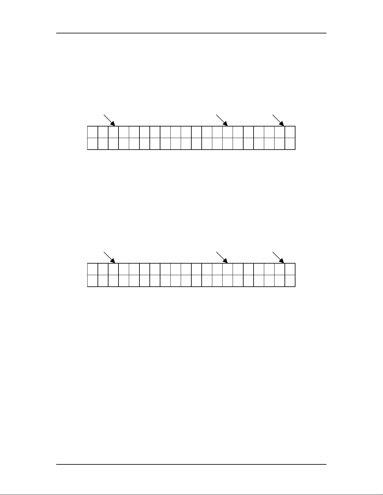
Auto detection is ON Pro Logic decoding is OFF
A u t o : O N P L : O F F
O F F O N O F F O N
Fig. 1-1 AUTO menu option with auto detection enabled and Pro Logic disabled
.
Through it’s SETUP menu TCS offers 8 hardware presets. Hardware presets tell TCS
how many and what kind of loudspeakers are connected. TCS can also automatically
assign any of these 8 presets to stereo or multi channels source. This is accomplished
through CONF menu option. TCS is factory preset to assign set-up #8 to stereo and set-up
#1 to multi channel source. For detailed description of the SETUP and CONF menu refer
to Chapter 4.
TCS offers two auxiliary stereo outputs. By using AUX menu option each of these
outputs can be configured as MAIN or ZONE output. Both outputs are factory preset to
MAIN, meaning that A1/2 outputs are set to be used as front Left/Right subwoofer
outputs and A3/4 as Tact Surround Center channel (both A3 and A4 output the same
signal).
The following are the three most common configurations used with TCS.
Tact Audio TCS Getting Started
REV 1.0 03/06/01 1 - 3
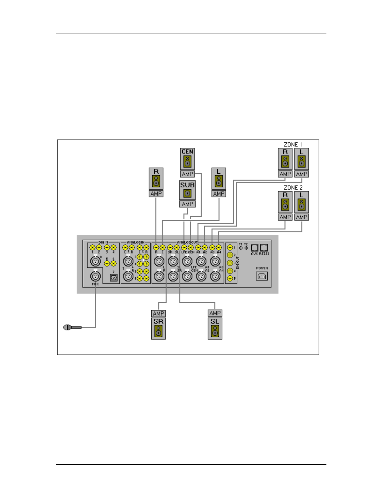
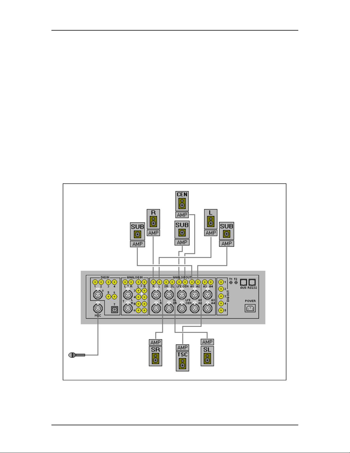
Configuration 1:
This is a basic 5.1 configuration. It consists of five full range loudspeakers; L
(left), R (right), SL (surround left), SR (surround right), CEN (center) and one subwoofer
channel, LFE. Connect your system as shown in Fig. 1-2. You can use either RCA (single
ended) or XLR (balanced) output. In this configuration, A1/2 and A3/4 outputs should be
configured as Zone 1 and Zone 2 outputs.
If you would like to use this hardware configuration connect your amplifiers to
appropriate TCS outputs as shown in the figure below.
Fig. 1-2 5.1 surround sound configuration with two zones
When all connections are in place, connect the power-cord and turn the rear mains switch
on.
NOTE: If you do not use zone outputs simply ignore them. If you want to use A1/2 and
A3/4 as two zones you first must configure them as zone outputs. This is done using
AUX menu option. Zones are controlled from ZONE1 and ZONE2 menus. Factory preset
disables zones.
Tact Audio TCS Getting Started
REV 1.0 03/06/01 1 - 4
NOTE: At this time there is no need to connect the microphone. Microphone is used only
during room correction measurement process.
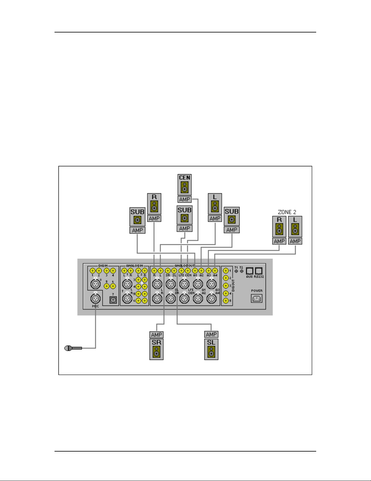
Configuration 2:
This is a 5.1 configuration with additional left and right subwoofers. In this
configuration A1/2 outputs should be configured as “Main” channels and A3/4 are
configured as Zone 2 outputs.
If you would like to use this hardware configuration, connect your amplifiers to
appropriate TCS outputs as shown in the Fig. 1-3.
Fig. 1-3 5.1 surround sound configuration with L/R subwoofer and one zone
When all connections are in place, connect the power-cord and turn the rear mains switch
on.
Tact Audio TCS Getting Started
REV 1.0 03/06/01 1 - 5
NOTE: If you do not use zone output simply ignore it. If you want to use A3/4 as a zone
you must first configure it as zone output. This is done using AUX menu option. Zones
are controlled from ZONE1 and ZONE2 menus. Factory preset disables zones.
NOTE: At this time there is no need to connect the microphone. Microphone is used only
during room correction measurement process.
Configuration 3:
This is Tact 6.1 configuration with additional left and right subwoofers and Tact
surround center channel. In this configuration A1/2 and A3/4 outputs are configured as
“Main” channels. A1/2 outputs are used for front left/right subwoofers and A3 is used as
Tact surround center channel.
If you would like to use this hardware configuration connect your amplifiers to
appropriate TCS outputs as shown in Fig. 1-4.
Fig. 1-4 5.1 surround sound configuration with L/R subwoofer Tact Surround
center channel

Tact Audio TCS Getting Started
REV 1.0 03/06/01 1 - 6
When all connections are in place, connect the power-cord and turn the rear mains switch
on
.
Step 2: Basic Playback
Turn TCS on from the front-panel power-switch. This will boot-up TCS and show the
TCS status screen. The status screen displays basic system parameters and its content is
source dependent. The following is the list of system parameters as displayed by the
status screen.
• Current mode
• LFE indicator
• Input selection
• Sampling frequency
• Correction mode
• Active correction indicator
• Master level in dB
The content of the status screen is source dependent. The following are few examples of
the status screen for a given source.
Example 1: DOLBY 3/2 with LFE
In the example shown in Fig. 1-5 current mode indicates that Dolby 3/2 source with LFE
(low frequency effects channel) enabled and with sampling frequency at 48 KHz is
connected at digital input D1. Room correction is bypassed as indicated by the active
correction indicator. Master volume is set at –12.1 dB.
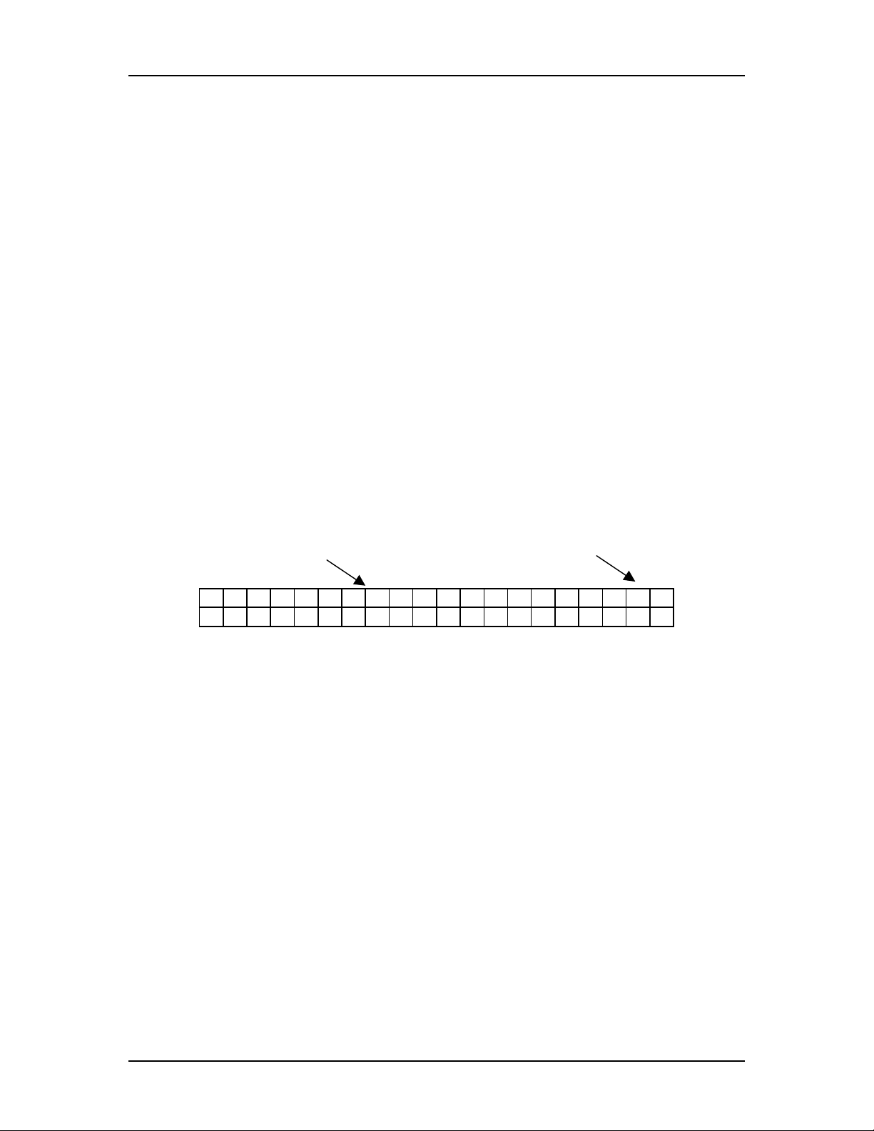
Current mode LFE indicator Input selection Sampling frequency
3 / 2 L F E D 1 F s = 4 8
B y p a s s * - 1 2 . 1 d B
Correction mode Active correction Master level dB
indicator
Fig. 1-5 TCS status screen with Dolby 3/2 & LFE enabled
Tact Audio TCS Getting Started
REV 1.0 03/06/01 1 - 7
Example 2: DTS
In the example shown in Fig. 1-6 current mode indicates that DTS source with sampling
frequency at 48 KHz is connected at digital input D3. Room correction is bypassed as
indicated by the active correction indicator. Master volume is set at –12.1 dB.
Current mode Input selection Sampling frequency
D T S D 3 F s = 4 8
B y p a s s * - 1 2 . 1 d B
Fig. 1-6 TCS status screen with DTS and LFE enabled
Example 3: STEREO
If stereo signal with sampling frequency at 44.1 KHz is detected at digital input D2 the
display will show the following status screen:
Current mode Input selection Sampling frequency
S T E R E O D 2 F s = 4 4
B y p a s s * - 1 2 . 1 d B
Fig. 1-7 TCS status screen with stereo source being played
One of the above screens will be displayed depending on the source connected to TCS
input. Your TCS should at this point produce stereo or surround sound. To control master
volume use VOLUME remote control buttons, or simply turn the wheel.
When using TCS without the correction feature, it might be necessary to manually adjust
the level for the each channel. The LEVEL menu contains a digital volume control for
each channel. To access the LEVEL menu, press remote control MENU and scroll the
cursor to LEVEL, then press the ENTER button. You can now adjust the level for each
channel by using remote control UP and DOWN arrow buttons.
Note that level settings can be different for each correction preset. BP indicates that you
are setting the levels for BYPASS mode. When using the correction feature, the system
will automatically adjust all speaker levels except for BYPASS mode.
Tact Audio TCS Getting Started
REV 1.0 03/06/01 1 - 8
L E F T R I G H T C R : B P
0 . 0 - 0 . 1 d B
→
→→
→
←
←←
←
S U R L S U R R C R : B P
- 1 . 2 - 0 . 5 d B
→
→→
→
←
←←
←
C E N T S U B C R : B P
- 1 . 1 - 2 . 3 d B
→
→→
→
←
←←
←
A U X 1 A U X 2 C R : B P
- 1 0 . 2 - 1 0 . 6 d B
→
→→
→
←
←←
←
A U X 3 A U X 4 C R : B P
- 1 0 . 2 - 1 0 . 6 d B
Fig. 1-8 TCS channel level trim controls – LEVEL menu
NOTE: In order to permanently save new parameters into the internal memory you must
cycle power OFF and ON by using remote control STANDBY button.
NOTE: This menu has no effect on A1/2 and A3/4 outputs if they are configured as
zones.

Tact Audio TCS TCS Architecture
REV 1.0 03/06/01 2-1
C
HAPTER
2
TCS Architecture
This chapter briefly outlines the fundamentals of TCS design. It is intended to
quickly provide users with the basic understanding of TCS operation and internal
architecture.
TCS is a collection of state of the art digital and analog technologies. Internal
architecture is divided into two major blocks: Analog and digital. These two blocks are
completely separated. This separation is essential for any system of this complexity and
analog signal quality.
Analog input and output circuitry is designed based on the latest in 24 bit /96 KHz
ADC and DAC technology. Fully modular design allows for easy future upgrades.
Carefully selected components, for the analog input and output stage combined with
individual power regulation on all analog outputs, ensure highest analog signal quality.
TCS signal processor consists of ten Motorola DSP processors and one
supervising controller. Signal processor is designed to provide room correction on all
supported surround sound channels, all necessary measurement functions, time
alignment, level balancing etc. The supervising controller runs Tact proprietary real time
operating system designed to interact with user remote control and PC commands.
TCS is designed to operate at 44.1, 48 and 96 KHz sampling rate. Note that when
in surround sound mode, sampling frequency is limited by Dolby and DTS to 48 KHz.
However, TCS will play any of the above sampling frequencies when in stereo mode.
Tact Audio TCS TCS Architecture
REV 1.0 03/06/01 2-2
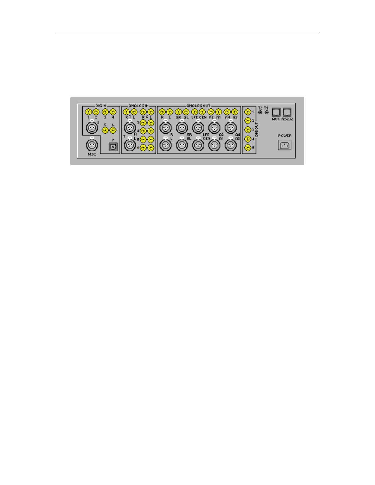
2.1 Connections
The TCS back panel is shown in Fig. 2-1. It is divided into four audio signal
sections: digital input, analog input, analog output and digital output sections.
Fig. 2-1 TCS back panel
Digital Inputs There are eight digital inputs, numbered 1 through 8. All inputs are
SPDIF. The exceptions are input number 7, which is TOSLINK and
input number 8, which is AES/EBU type.
Digital Outputs There are five digital outputs, numbered 1 through 5. Digital outputs
output the same audio signal as analog outputs.
Digital output 1 is mapped to Left/Right
Digital output 2 is mapped to Surround Left/Surround Right
Digital output 3 is mapped to LFE/Center
Digital output 4 is mapped to A1/A2
Digital output 5 is mapped to A3/A4
Analog Inputs There are seven stereo analog inputs. They are numbered 1 through
7. All analog inputs are single ended except input number 7, which
is balanced.
Analog Outputs There are five stereo analog outputs. All outputs are single ended
and balanced. Outputs A1 and A2 can be configured as Zone 1
outputs or as Left/Right subwoofer outputs. Outputs A3 and A4 can
be configured as Zone 2 outputs. Or alternately, A3 can be
configured as a surround center channel as used in TSC mode.
Microphone Input TCS comes with a calibrated measurement microphone. During the
setup process, the microphone should be connected to the MIC
input.
Pin 1 GND

Tact Audio TCS TCS Architecture
REV 1.0 03/06/01 2-3
Pin 2 SIG
Pin 3 +9V
Note: Make sure TCS is turned off at the main switch, before
connecting the microphone
RS232 I/O There are two RS232 connectors. They are labeled RS232 and AUX.
RS232 is used to connect to the PC during the setup process. It can
also be used for RS232 remote control. The AUX connector is used
as the RS232 pass-through. Its primary purpose is to daisy chain a
number of Tact products.
Trigger Outputs Trigger outputs provide a +12V/50mA signal for external device
triggering.
NOTE: Single ended RCA analog output signals L, R, SL, SR, LFE, CEN, A1, A2, A3,
A4 are the same as the corresponding balanced XLR output signals. Either one
can be used to connect TCS to corresponding power amplifiers.
NOTE: Digital outputs D1, D2, D3, D4, D5 are mapped in the following way: D1
outputs L and R channels, D2 outputs SL and SR channels, D3 outputs CEN and
LFE channel, D4 outputs AUX1 and AUX2 channels, D5 outputs AUX3 and
AUX4 channels. These signals are exactly the same as their corresponding
analog output signals.
WARNING
Before connecting or disconnecting Tact measurement microphone make sure to
turn TCS off by using the front panel power switch.
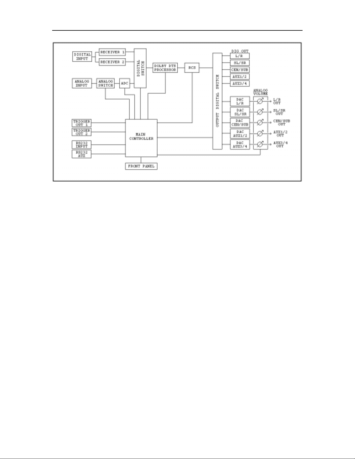
2.2 TCS Block Diagram
The TCS basic system block diagram is shown in Fig. 2-2. Audio input signal can
be connected to one of eight digital inputs or to one of seven analog stereo inputs. TCS
provides ten analog and ten digital outputs (five stereo). All analog outputs have digitally
controlled analog volume control circuitry. All inputs and outputs are designed for 24 bit
audio data. TCS supports 44.1, 48 and 96 kHz sampling rates.
Tact Audio TCS TCS Architecture
REV 1.0 03/06/01 2-4
Fig. 2-2 TCS system block diagram
The Main Controller handles: Front panel display, IR remote control functions,
RS232 Input and RS232 Auxiliary communication ports, trigger output 1 and 2, and all
necessary internal switching and data transfers.
The Digital Input Block consists of six SPDIF, one AES/EBU, one TOSLINK
input and two independent digital audio receivers. This unique architecture with two
digital receivers allows simultaneous digital input signal assignment to main output and
to zone 1 and 2.
The Analog Input Block consists of six single ended (RCA) and one balanced
(XLR) inputs. Analog inputs are connected to a 24bit/96KHz analog-to-digital converter
(ADC). ADC sampling frequency can be set to 44.1, 48 and 96 KHz, by using the “ADC”
front panel menu option.
The Digital Output Block consists of 5 SPDIF (RCA) type outputs. Each SPDIF
signal carries two audio channels. The Digital output signal level is controlled by the
master volume control and by other digital level control menu options.
The Analog output Block consists of 10 channels with both single ended (RCA)
and balanced (XLR) connectors. The Analog output signal level is controlled by the
master volume and by other digital volume control menu options. TCS is also equipped
with digitally controlled analog volume adjustment circuitry. This circuit provides analog
attenuation and gain of up to +6.0 dB for each channel.

Tact Audio TCS TCS Architecture
REV 1.0 03/06/01 2-5
TCS is equipped with two 12V/50 mA trigger outputs. Trigger events are user
programmable.
RCS module is a real time digital signal processor consisting of 10 Motorola DSP56300
processors. This module is used to perform room impulse response measurement and real
time room correction on all channels.
NOTE: If AUX1/2 and AUX3/4 are used as two zones, room correction is not
implemented on these channels.

Tact Audio TCS Remote Control
REV 1.0 03/06/01 3-1
C
HAPTER
3
Remote Control
TCS is designed to be controlled by the remote control and PC software. The only
exception is master volume control, which can be controlled by the remote control, PC
and front panel wheel. The remote control is designed with three basic objectives:
• Support intuitive menu driven user interface
• Eliminate the need to read the manual all over again
• Eliminate excessive number of buttons
This chapter explains all remote control functions.
Tact Audio TCS Remote Control
REV 1.0 03/06/01 3-2
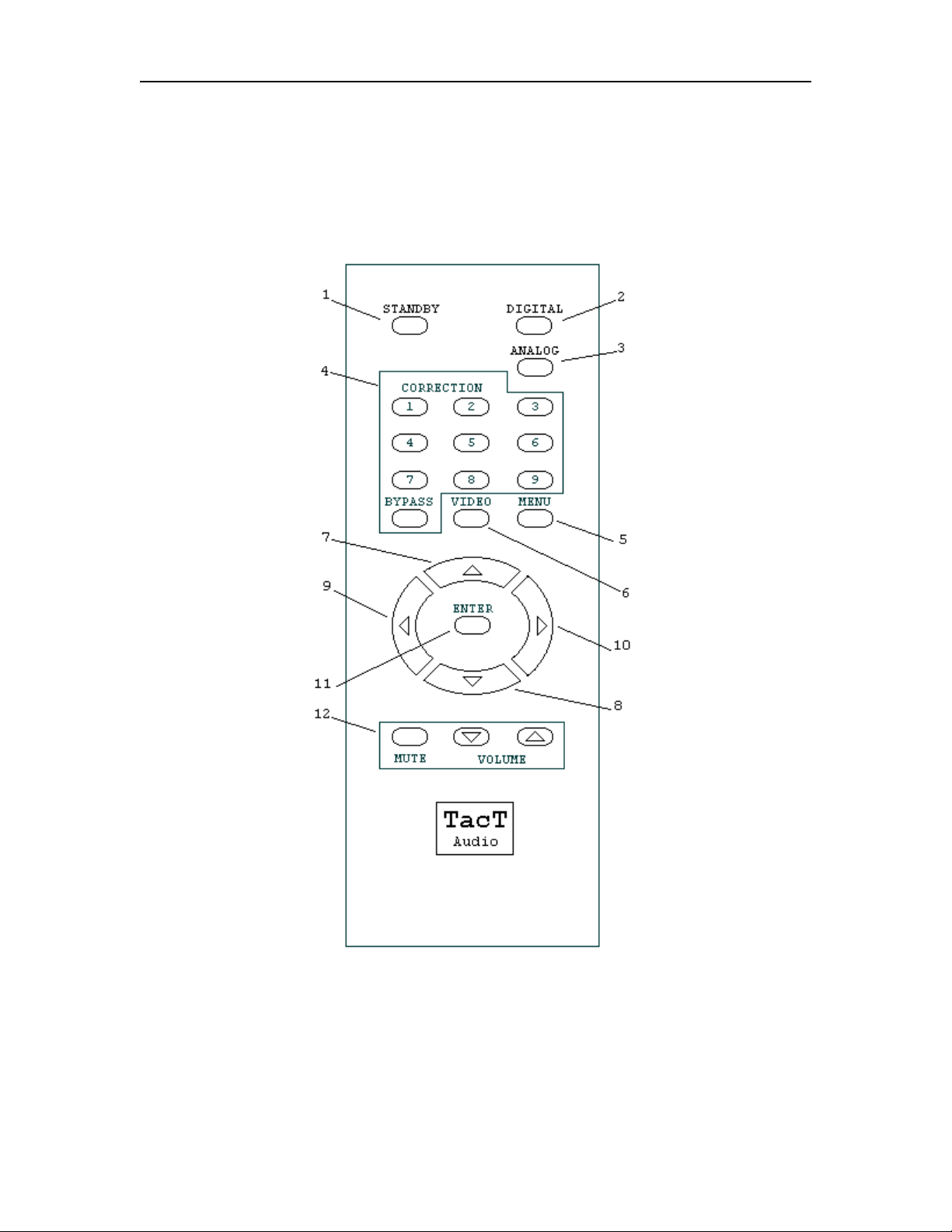
The TCS remote control is shown on Fig 3-1. The remote control is used to access
front panel display controls and menus. The following is a functional description of all
the buttons on the remote control.
Fig 3-1 TCS Remote control

Tact Audio TCS Remote Control
REV 1.0 03/06/01 3-3
1. STANDBY
STANDBY button will turn TCS ON or it will place
it into standby mode. When in stand by, the unit is
placed into low power consumption mode. The main
power line is not disconnected.
2. DIGITAL
DIGITAL button will sequentially select one of 8
digital inputs.
3. ANALOG
ANALOG button will sequentially select one of 7
analog inputs.
4. CORRECTION Block
CORRECTION consists of 10 buttons. They are
numbered from 1 to 9 and one of them is labeled as
BYPASS. Pressing BYPASS will place room
correction into bypass mode – no correction.
Pressing one of the remaining nine buttons will
engage a corresponding room correction preset.
5. MENU
MENU button will switch the front panel display
from the status screen to the main menu screen.
6. VIDEO
VIDEO button is used to control the external Tact
video switcher. This button has no effect on any of
TCS functions.
7. UP Button
UP button is used to increment selected menu
options.
8. DOWN Button
DOWN button is used to decrement selected menu
option.
9. LEFT Button
LEFT button is used to scroll through menus.
10. RIGHT Button
RIGHT button is used to scroll through menus.
11. ENTER Button
ENTER button will select the menu option that is
marked by the blinking cursor.
12. VOLUME Block
The VOLUME block consists of three buttons.
Pressing the MUTE button will mute/un-mute all
enabled channels. The MUTE does not affect zone 1
and 2 signals.
Pressing the up/down level control buttons will
increment/decrement the master level.

Tact Audio TCS Menus
REV 1.0 03/06/01 4-1
C
HAPTER
4
Menus
This chapter describes TCS front panel display menus. All TCS features are
accessible by the remote control through its front panel menus. However room correction
process requires PC connection and Tact room correction software. Once room correction
process is completed, you can switch between correction presets and bypass mode by
using the remote control.
Loading...