

Page 1

Tact-2.2 XP
RCS/DRC Quick Start
Tact Audio Inc.
201 Gates Road
Little Ferry, NJ 07643
USA
3/23/2007 RCS/DRC Quick Start 1 of 20
Page 2

3/23/2007 RCS/DRC Quick Start 2 of 20
Page 3

Tact-2.2 XP RCS/DRC Quick Start
This quick start will guide you through the entire room correction process. The
quick start is divided into four steps.
Step 1 Explains how to prepare 2.2 XP for the correction process.
Step 2 Deals with room measurement.
Step 3 Explains how to perform standard room correction based on one reference target
curve.
Step 4 Explains how to perform dynamic room correction based on one reference target
curve and eight additional dynamic target curves.
Before continuing with the room correction process it is strongly recommended
that you connect your 2.2 XP to your audio system and that you make sure that it
properly plays music on all connected channels.
In this example we assume a 2.2 system with two main loudspeakers and two
subwoofers. We also assume that the subwoofers need to have a crossover filter of 200
Hz.
The subwoofer to main loudspeaker crossover frequency is usually provided by
the loudspeaker manufacturer. If you do not have this information you can perform a
system measurement, load the measurement data, and based on the loudspeaker response
easily determine this parameter. There is no definition for what the exact value of the
crossover frequency is, but rather there is a range of frequencies that you can use to
experiment with. The Tact 2.2 XP allows for on-the-fly crossover and target curve
adjustments which makes the process of selecting this parameter easy, fast, and extremely
accurate.
If your subwoofers are self powered they usually have a built in crossover
network. To take full advantage of the 2.2 XP crossover feature, it is recommended that
you disable the subwoofer internal crossover filter or set it to its maximum value.
3/23/2007 RCS/DRC Quick Start 3 of 20
Page 4
Step 1 - Preparing the Tact-2.2 XP for Correction
Before using the 2.2 XP as a correction system make sure of the following:
1. Tact-2.2 XP is powered and properly connected. The PC RS232 port has to be
connected to the Tact-2.2 XP RS232 INPUT connector and not to the Tact-2.2 XP
RS232 AUX port connector.
2. Place the microphone at the listening position and connected it to the Tact-2.2 XP
microphone input.
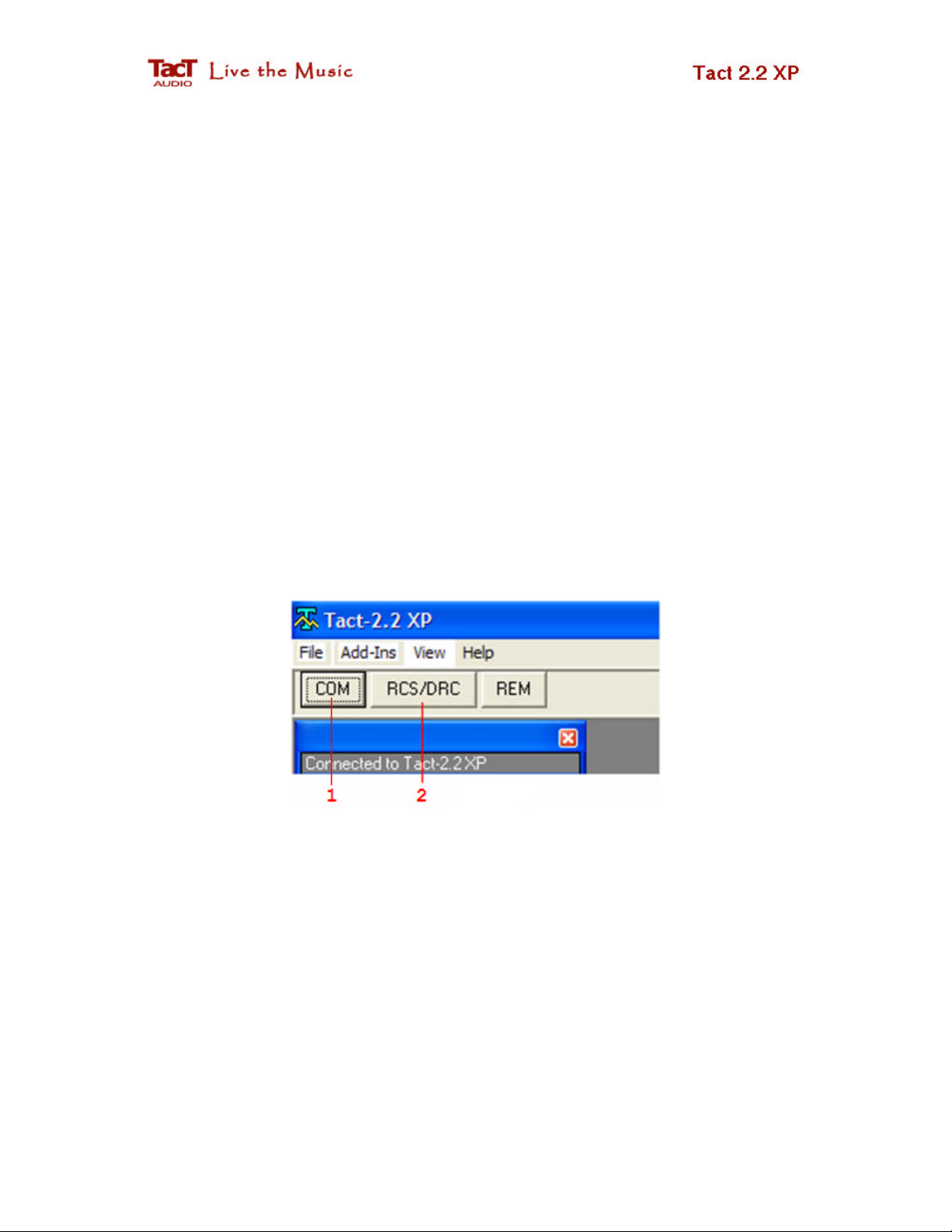
3. Start the Tact-2.2 XP program. Click on the COM button (1 in Fig.1) to enter the
RS232 Connection to Tact-2.2 XP screen. Verify that RS232 communication is
functioning properly and then exit this screen.
If all of the above is correct, click on the RCS/DRC button (2 in Fig.1) to enter the
correction screen.
Fig. 1. Click on RCS/DRC button to enter the correction screen.
3/23/2007 RCS/DRC Quick Start 4 of 20
Page 5

Step 2 - Measurements
Click on the
BP
(bypass) option (1) on the
As soon as you enter the RCS/DRC screen the 2.2 XP status data will be uploaded and
displayed on the screen.
The next step in the room correction process is the room measurement.
• Select bypass correction preset and disable crossover filters
Action panel. This will place the 2.2 XP into
bypass mode.
Fig. 2. Action panel.
Note that if system measurement is performed in correction preset other than BP,
the measured response will include room response combined with correction and
crossover filter response. If the measurement is performed in BP with enabled
crossover filters, the measured response will include room response and crossover
filters response.
3/23/2007 RCS/DRC Quick Start 5 of 20
Page 6
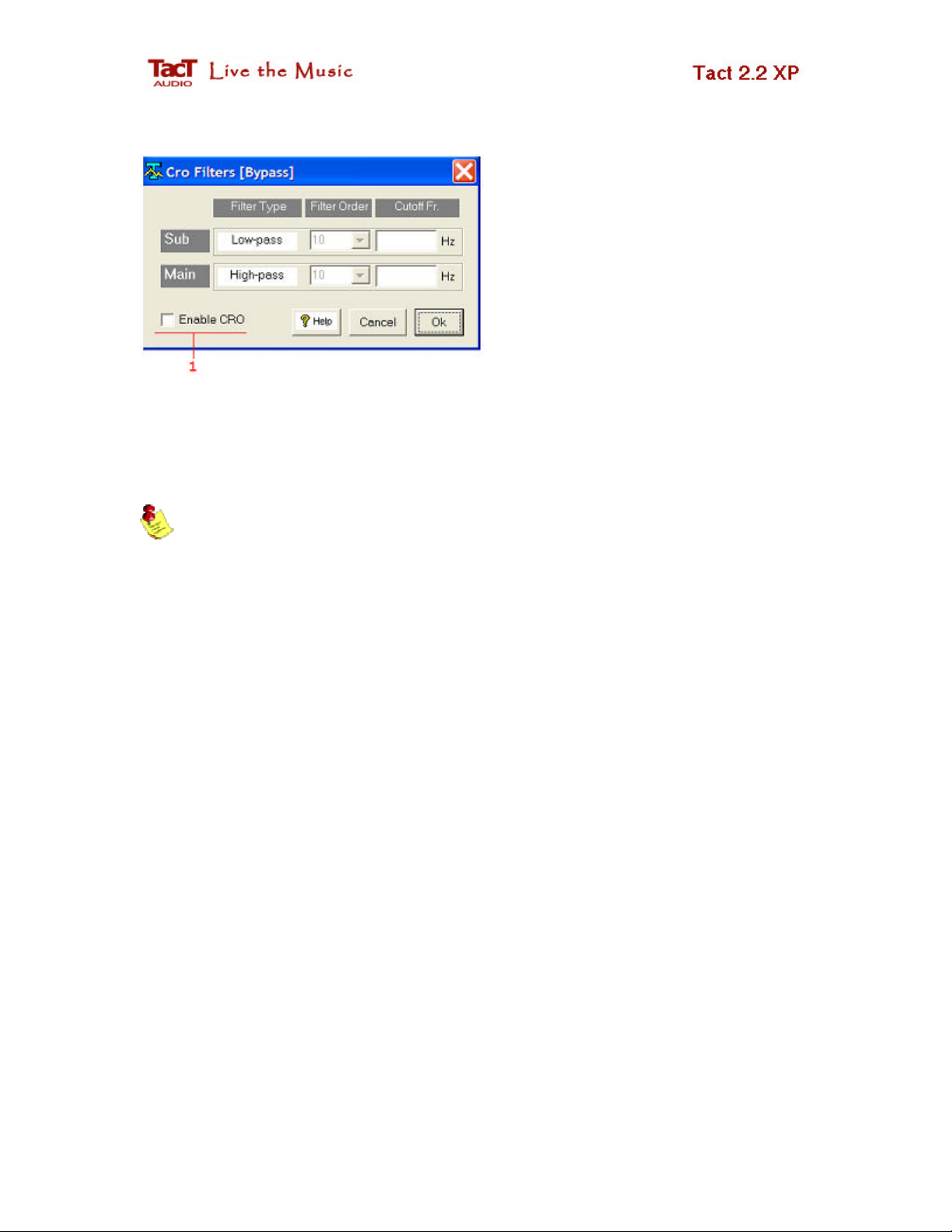
Use the
Tools
pull-down menu and
select the Crossover menu option.
Uncheck Enable CRO check box
(1) to disable bypass preset
crossover filtering. Click on OK to
close this window.
Fig. 3. Crossover filter selection.
When crossover filters are disabled “None” is shown in both the CRO-SUB and CRO
filter description fields (see Fig. 5 panel 2). You can also enter Cro Filter screen by
double clicking in any of these fields.
Note that all measurements that are intended to be used for correction purposes
must be done while the 2.2 XP is placed in bypass correction mode with the crossover
filters disabled. If measurements are performed in a correction preset different than
bypass, the measurements will then include correction filters in the measured response.
Also, if crossover filters in bypass mode are not disabled, their response will be
included in the measured response.
• Enter the Measurement screen
On the Action (Fig. 2) panel click on the MSR button (2) to enter the measurement
screen (see Fig. 4). The measurement screen is used to perform room response
measurements. There are only a few measurement parameters that need to be set before
starting the measurement process.
3/23/2007 RCS/DRC Quick Start 6 of 20
Page 7

Fig. 4. Measurement screen.
On the System Configuration (1 ) panel click on the En check box to enable/disable the
appropriate channel. For example, if your system consists of two main channels and two
subwoofers (2.2 mode), enable all four channels. If your system consists of two main
channels and one subwoofer (2.1 mode), enable the LEFT and RIGHT channels and one
of the subwoofer channels, depending on which output your subwoofer is connected to.
Since in this example we have assumed a 2.2 configuration select all of the En check
boxes.
On the Measurement (2) panel set measurement parameters.
• Output Pulse. This parameter sets the relative level of the output measurement
pulse. Minimum level is 1% and maximum level is 100%. This value affects
microphone preamp gain as displayed in (3). Stronger output pulses will result in
smaller microphone preamp gain and better measurement signal to noise ratio.
3/23/2007 RCS/DRC Quick Start 7 of 20
Page 8

• Initial Delay. Usually you would keep this value set to 0.
• Countdown. If you do not want to be in the room while measurement is in
progress, set this parameter to a few seconds to allow you to exit the room. For
example, if Countdown = 10 the system will wait for 10 seconds before it starts
pulsing.
• Average. This is a very important measurement parameter. It equals the number
of measurements that are averaged prior to being saved. The averaging process
reduces the effect of random environmental noise. Typical Average values go
from 10 to 30.
• On the Measurement File (4) panel select measurement file 1. The Tact-2.2 XP
offers 7 measurement files. Measurement files are assigned to correction presets
in a later step.
Click on the START button to initiate the measurement process. You can cancel the
measurement process at any time by clicking on the CANCEL button; you are then free
to restart the measurement process.
When you click on the START button, the 2.2 XP will start the measurement sequence
with microphone calibration pulses. These pulses are used to determine the optimum
microphone preamp gain for all four (enabled) channels. When all channels are tested the
final microphone preamp gain will be displayed in (3). You can reduce the microphone
preamp gain by increasing the output pulse level.
When the measurements are complete, all measured room responses will be saved in the
selected measurement file. Measurements are permanently saved in 2.2 XP internal
memory.
A new measurement that uses the same measurement file will erase the old data
and will save new measurement data in its place.
Click on Exit button to exit this screen.
3/23/2007 RCS/DRC Quick Start 8 of 20
Page 9

Step 3 - Correction
After measurements are completed and you have exited the measurement screen, the
following RSC/DRC screen should be displayed.
Fig. 5. Correction screen
Note that the Tact-2.2 XP is in bypass correction mode (1) and both crossover options are
set to None (2).
Click on (3) to select correction preset 1. Tact-2.2 XP will engage correction preset 1 and
upload all target curves and crossover filters assigned to these preset. If you have just
received your 2.2 XP preset 1 will contain factory preprogrammed target curves and
crossover filters. To view uploaded curves click on appropriate target curve button.
3/23/2007 RCS/DRC Quick Start 9 of 20
Page 10

Click on the
File No
panel and ma
ke sure that
On the
Measurements
panel (
Fig. 5
panel
4)
In the
Target
menu make sure that the
One Target
Fig. 6
.
File No
panel. Use this panel to select
measurement File No: 1 is assigned to correction
preset 1. We assign measurement File No: 1 to
preset 1 because in step 2 all measurement data
was saved in measurement File No: 1. In another
words, we want to perform correction based on
measurement data saved in File No: 1.
measurement file for the correction process.
select M-L (1) and then right mouse click followed
by a left mouse click to load the left channel
measurement data.
Repeat this for the remaining 3 channels. The
Fig. 7. Measurements and Correction Filter panel. Use this panel to upload
measurements and correction filter response from 2.2 XP internal memory.
Curve (1) option is selected.
When the One Target Curve option is selected, the 2.2
XP will apply the same target curve to both the Left and
the Right channel. When the Two Target Curves
option is selected, the 2.2 XP can apply different target
curves to the Left and the Right channel.
3/23/2007 RCS/DRC Quick Start 10 of 20
Fig. 8. Target menu.
Page 11

After all this is completed the following RCS/DRC screen is displayed:
Fig. 9. Correction screen with loaded measurement response and target curve.
Note that the target curve displayed on this screen was uploaded from the 2.2 XP
when preset 1 was selected. Use the T-L button to enable/disable target curve trace,
since this is not necessarily the target curve you initially want to use.
From the measurement data, for this particular example, we select a 12-th order 200 Hz
crossover filter and the QS_30.COR target curve. To select crossover filter, use the
Tools pull-down menu and select the Crossover menu option.
3/23/2007 RCS/DRC Quick Start 11 of 20
Page 12

Check
Enable CRO
check box
and
Click on the
T-L
button and then right mouse click
select (in this example) a 12-th
order 200 Hz crossover filter for
both channels. Click on Ok to exit
this screen.
Fig. 10. Crossover screen.
do display the individual target curve menu.
Click on (3) to load one of the supplied target
curves. For this example select the QS_30.COR
target curve. After the target curve is loaded, the
RCS/DRC screen should look like the one shown
in Fig. 12.
Fig. 11. Target curve pop up menu.
3/23/2007 RCS/DRC Quick Start 12 of 20
Page 13
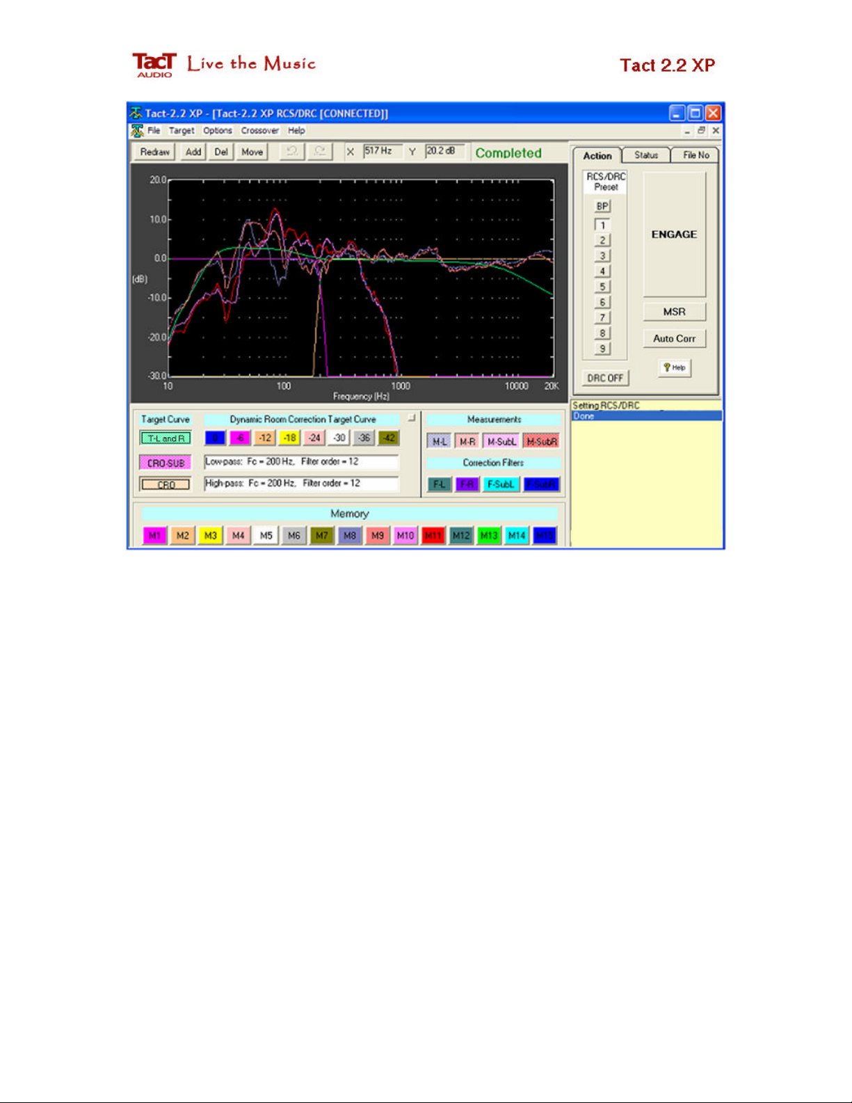
Fig. 12. Correction screen with selected measurements, target curve and crossover filters.
Up to this point we have done the following:
• Performed measurements in bypass correction mode (BP) with disabled crossover
filters on all four channels and saved measurement data in the measurement File
No: 1.
• Assigned measurement File No: 1 to preset 1.
• Selected 12-th order 200 Hz crossover filters.
• Selected target curve QS_30.COR
To engage these settings and to perform a listening test, click on the ENGAGE button. In
a split of a second the 2.2 XP will perform room correction based on the above settings.
You are ready to perform your first listening test.
While the music is playing you can make modifications to the target curve or make
another crossover selection. Once you are done with the changes you wish to make, click
on the ENGAGE button to perform another listening test. In this way, while listening to
your favorite track, you can make on the-fly-changes until you get your own perfect
sound.
3/23/2007 RCS/DRC Quick Start 13 of 20
Page 14

How to modify target curve?
Modifying a target curve and performing new correction based on the modified
target curve is an extremely simple task.
• Select T-L and R button (Fig. 11) to display loaded target curve.
• Right mouse click to display Target menu and then select Edit option
(Fig. 11 option 1).
Selecting Edit option will display red square points (referred to as corners) on the target
curve. These corners can be deleted, moved around and additional corners can be added
to the target curve.
Fig. 13 Target curve edit controls.
To edit selected target curve use edit target curve control buttons shown in Fig. 13. These
buttons are located in the upper left corner of the screen.
• To move corners around select Move button. Place the mouse pointer over
desired corner, press down the l eft mouse key and while holding it down drag the
selected corner to a new position. Release the left mouse key to complete the
move operation.
• To delete a corner select Del button. Place the mouse pointer over desired corner
and then left mouse click to delete that corner.
• To add a corner select Add button. Place the mouse over target curve where you
want to place the corner and than left mouse click.
After all target curve changes are completed click on ENGAGE button. In a split of a
second 2.2 XP will recalculate entire room correction including target curve and/or
crossover parameter changes.
3/23/2007 RCS/DRC Quick Start 14 of 20
Page 15

Step 4 - Dynamic Room Correction®
Standard room correction as implemented in Step 3 is based on one reference
target curve. This target curve is applied once and one correction filter is used for all
listening levels. If you are a Tact user (a 2.2 X, 2.0 S or TCS owner), you may have
noticed that as you changed the listening level of your system, the tonal balance of the
music completely changes. The reason for this change in tonal balance is not due to a
deficiency of your system but rather is due to the way we perceive the loudness of
different frequencies at different listening levels.
Let us look at one possible example. Let us assume that your listening level is -6
dB (a 93.9 relatively readout on the 2.2 XP), and that for that listening level you found an
optimum target curve that makes your system deliver perfect performance. If you change
the listening level from -6 to, let's say, -18 dB (81.9), you will notice a significant change
in the system tonal balance even though the correction is still performed using the same
target curve. One possible way to cure this problem is to use two correction presets (the
2.2 X, 2.0 S and TCS offer 9 correction presets). Preset #1 holds your perfect correction
for a listening level of -6 dB. For preset #2 create another target curve that will result in a
correction with the same tonal balance as the one used at -6 dB in preset #1. At the end of
this process you will have two correction presets, preset #1 optimized for the listening
level of -6 dB and preset #2 optimized for the listening level of -12 dB. When your
listening level is -6 dB you simply engage preset #1, and when your listening level is -12
dB you engage preset #2. In this way you can have a listening experience with the same
tonal balance at -6 dB and -12 dB. Well, what happens if you switch to another listening
level, and another one, and what happens if you keep changing the level too often? What
happens if you forget to switch to another preset when you change the level? You will
experience the equal loudness curve effect discovered at Bell Labs in the 1930s.
Equal loudness curves describe human hearing over all audible levels and
frequ encies. Let us consider an example with 1000 Hz and 100 Hz tones.
3/23/2007 RCS/DRC Quick Start 15 of 20
Page 16

Case 1: If we listen to a 1000 Hz tone at 80 dB, a 100 Hz tone has to be played at about
83 dB so that they both have the same perceived loudness. A 100 Hz tone needs about 3
dB more sound pressure so that it will have the same perceived loudness as a 1000 Hz
tone.
Case 2: If we listen to a 1000 Hz tone at 70 dB, then a 100 Hz tone has to be played at
about 87 dB so that they both have the same perceived loudness. A 100 Hz tone needs
about 7 dB more sound pressure so that it will have the same perceived loudness as a
1000 Hz tone.
Case 3: If we listen to a 1000 Hz tone at 60 dB, then a 100 Hz tone has to be played at
about 71 dB so that they both have the same perceived loudness. A 100 Hz tone needs
about 11 dB more sound pressure so that it will have the same perceived loudness as a
1000 Hz tone.
From these three cases it is obvious that in order to preserve the same perceived
loudness of these two tones we need to apply a correction to 100 Hz tone that is listening
level dependent. If we listen to these two tones at 80 dB then we need to increase the
sound pressure (by increasing output signal power) of the 100 Hz tone by 3 dB, at a
listening level of 70 dB we need to increase it by 7 dB, and at 60 dB we need to increase
it by 11 dB. From the above graph it is also clear that different frequencies need different
correcti on levels to produce the same perceived loudness of the reference 1000 Hz tone.
3/23/2007 RCS/DRC Quick Start 16 of 20
Page 17

How does Tact-2.2 XP solve the equal loudness problem?
In addition to standard, one target curve correction, then Tact-2.2 XP offers 8
additional dynamic target curves. These target curves are labeled from 0 dB to -42 dB in
increments of -6 dB.
Fig. 14. Dynamic Room Correction Target Curve control panel.
If your listening level is 0 dB (99.9 displayed on the front panel), the Tact-2.2 XP
will perform room correction by adding the reference target curve to the 0 dB dynamic
target curve. If your listening level is -6 dB, the Tact-2.2 XP will perform room
correction by adding the reference target curve to the -6 dB target curve. This process
will repeat for the -12, -18, -24, -30, -36 and -42 dB listening levels. If, for example, the
listening level is -7.5 dB, the 2.2 XP will use the -6 dB and -12 dB target curves and, by
interpolation, will derive a new dynamic target curve for -7.5 dB. This new target curve
will then be combined with the reference target curve to perform room correction for this
particular listening level.
For every master level change of 0.1 dB, the Tact-2.2 XP will calculate a new
dynamic target curve, will combine it with the reference target curve, and will both apply
the selected crossover filter and recalculate the entire room correction algorithm for all
four channels. All of this happens on the fly and without any interruption to the music
that you are listening to. How to setup dynamic target curves?
1. Set the 2.2 XP to a listening level of your choice. To make the setup easier choose
one of the following listening levels: 0 dB (99.9), -6 dB (93.9), -12 dB (83.9), ..., 42 dB (57.9). For the sake of clarity in this tutorial, we assume that a -12 dB
listening level was selected. For this listening level perform room correction
based on one reference target curve as described in the previous three steps of the
RCS/DRC - Quick Setup guide.
2. Enable the DRC feature by clicking of the DRC button in the Action panel.
3/23/2007 RCS/DRC Quick Start 17 of 20
Page 18

3. In the File menu select the Load Dynamic Target Group menu option and then
load the DRC_Flat.grp group file. This will load all dynamic target curve buffers
with flat (no correction) target curves.
4. Click on the Engage button to load dynamic flat target curves into 2.2 XP.
5. Lower the listening level for -6 dB to -18 dB (81.9). Click on the dynamic target
curve labeled -18 dB, then right mouse click and select the Edit menu option.
This will select the -18 dB dynamic target curve for editing. Make a modification
to this target curve (probably something similar to the example shown bellow)
and then click on the Engage button. This will load all modifications to 2.2 XP.
You can perform listening tests to determine if the change you made will result in
tonal balance that is equivalent to the one you had at the -12 dB listening level.
Keep modifying the -18 dB target curve until you are satisfied with the correction
you made. Make sure to click on the Engage button prior to any listening test.
6. Lower the listening level by another -6 dB to -24 dB (73.9). Select the -24 dB
dynamic target curve and repeat the procedure described in the previous step.
Repeat the same process for -32, -36 and d-42 dB target curves. See figure
bellow.
7. Set the listening level to -6 dB, which is 6 dB above the reference listening level.
Select the -6 dB dynamic target curve and keep modifying it until its tonal
balance matches the one you had at the reference listening level of -12 dB. Note
that in this case the listening level is above the reference listening level and most
likely the -6 dB dynamic target curve should have the same shape with slope
opposite that of the dynamic target curves that are bellow reference listening level
(see figure below). Repeat this process for the remaining 0 dB target curve.
3/23/2007 RCS/DRC Quick Start 18 of 20
Page 19

Fig. 15. Eight dynamic target curves.
If you want to listen to any change you made, either to the target curves or to the
crossover filter, you must click on the Engage button.
To evaluate the effect of Dynamic Room Correction® click on DRC-ON(OFF)
button. When this button is set to DRC-ON you will listen to room correction
performed on the reference target curve and eight dynamic target curves. When this
button is set to DRC-OFF you will listen to room correction performed on the
reference target curve only.
3/23/2007 RCS/DRC Quick Start 19 of 20
Page 20

Was this document helpful? Please send you comments and suggestions to Tact
support team at:
support@tactaudio.com
3/23/2007 RCS/DRC Quick Start 20 of 20
 Loading...