

Page 1

Owner ’s Manual
M2150 / S2150
True Digital Amplifier
Page 2

Blank Page
Page 3
WARNING
TO REDUCE THE RISK OF FIRE OR ELECTRIC SHOCK, DO
NOT EXPOSE THIS APPLIANCE TO RAIN OR MOISTURE.
CAUTION
RISK OF ELECTRIC
SHOCK DO NOT OPEN
CAUTION: TO REDUCE THE RISK OF ELECTRICAL SHOCK,
DO NOT REMOVE COVER. NO USER-SERVICEABLE PARTS
INSIDE. REFER SERVICING TO QUALIFIED PERSONNEL.
The exclamation point within an equilateral triangle is intended to alert
the user to the presence of important operating and maintenance (servicing) instructions in the literature accompanying the product.
The lightning with arrowhead symbol within an equilateral triangle is
intended to alert the user to the presence of “Dangerous Voltage”
within the product’s enclosure that maybe of sufficient magnitude to
constitute a risk of electrical shock to a person.
3T act Audio
Page 4

Important Safety
Instructions
1. Read these instructions entirely before installing or operating this equipment.
2. Keep these instructions.
3. Heed all warnings.
4. Do not use this equipment near water or allow it to become wet.
5. Do not block any ventilation openings. Install in accordance with the
manufacturer’s instructions.
6. Do not install near any heat sources such as radiators, heat registers, stoves, or
other appliances (including amplifiers) that produce heat,; doing so may
damage the unit and present a fire hazard.
7. Do not defeat the safety purpose of the polarized or grounding-type plug. A
polarized plug has two blades with one wider than the other. If the provided plug
does not fit into your outlet, consult an electrician for replacement of the outlet to
one that is polarized. To protect against electrical shock, match the wide blade
of the polarized plug to the wide slot in the outlet and fully insert the plug.
8. Protect the power cord from being walked on or pinched, particularly at plugs,
convenience receptacles, and the point where they exit the equipment. Do not
use this unit with a damaged cord or plug.
9. Only use attachments/accessories specified by the manufacturer .
10. Unplug this equipment during lightning storms or when unused for long periods of
time.
11. Refer all servicing to qualified service personnel.
1. Always unplug the unit from the electrical outlet before cleaning.
2. Do not use abrasive cleaners. Simply wipe the exterior with a clean soft cloth. A
small amount of nonabrasive cleaner may be used on the cloth to remove
excessive dirt or fingerprints.
CAUTIONCAUTION
“Note” symbol
4 T act Audio
Cleaning and
Maintenance
The >note< symbol indicates information very useful or essential to daily
operation.
Page 5
Acknowledgments
© 2003 T act Audio Corporation. All rights reserved.
No part of this document may be reproduced or transmitted in any form or by any
means, electronic, mechanical, photocopying or other wise, without the prior
written consent of the Tact Audio Corporation.
The information contained in this document is subject to change without
notice.
Registration
IMPORTANT!
Please record your serial number here for future reference. Y ou will need this for
future upgrades or should you ever require service on your M/S 2150.
M/S 2150 serial number: _____________________
Optional modules installed:
ADC analog input :__
5T act Audio
Page 6

Table of contents
Safety instructions 4
Acknowledgments/Registration 5
Unpacking the m/s 2150 7
Introduction 8
M/S 2150 Connections 9
Front Panel Controls 1 5
Remote Control 1 6
Front Panel Display 1 8
Main screen 18
MAIN menu 18
Saving Menu Settings 18
DELA Y menu 19
LEVEL menu 19
ADC menu 20
CRO menu 2 0
TRIG menu 21
DISPL menu 21
OPT menu 22
InOut menu 23
POL menu 23
REM menu 2 4
COMM menu 24
ADDR menu 2 5
LOCK menu 25
GAIN menu 26
CAUTIONCAUTION
6 T act Audio
TacT M/S2150 Software 27
Connect your M/S2150
to your Computer 2 8
Specification 29
Page 7

Unpacking the M/S 2150
Carefully remove the M/S2150 and accessory kit from the carton and check for
shipping damage. Contact both the shipper and TacT Audio immediately if the unit
shows any sign of damage from rough handling. All TacT Audio equipment is carefully
inspected before leaving our factory .
KEEP SHIPPING CARTON AND PACKING MATERIALS for future use or in the
unlikely event that the unit needs servicing. If this unit is shipped without the original
packing, damage could occur and void the warranty .
Accessories
Operating voltage
Y ou should find the following items in the accessory kit:
- one AC mains cord
- RJ1 1 data cable
- RJ11-to-RS232 adapter
- 15’ RS232 cable
- CD-rom with software
- remote control
- 2 AAA batteries
- one manual
The 2150 amplifier is configured for either 110 or 220/240 volt operation. The operating voltage is clearly marked on the outside of the box and also on the rear panel
beneath the AC mains connector .
BEFORE CONNECTING THE POWER, MAKE SURE THA T THE LABEL INDICA TING THE VOL T AGE MA TCHES THE VOL TAGE FOR YOUR COUNTR Y
The 2150 has three operating modes:
- OFF AC mains power is cut off, either via the front
panel mains switch, or by unplugging the amplifier from
the wall outlet.
- ST ANDBY The unit is powered but all outputs are muted and the
display is off. The amplifier uses very little current and
is “idling” or “sleeping”. Use the remote “ST ANDBY”
button to toggle between ON and ST ANDBY.
- ON Everything is powered and ready to use.
7T act Audio
Page 8

Introduction
Congratulations on your purchase of your M/S 2150. Y ou have now acquired the most
advanced stereo amplifier ever developed!
How does it work?
The digital input is taken to the central processor where it is reformatted into a
pulse width modulated signal of extreme precision. The pulse rate is measured at
precisely 384,000 pulses per second. Each pulse can have 256 different widths,
with the narrowest pulse being a mere 10 nanoseconds wide. The clock frequency
therefore is 98 MHz. The central processor uses proprietary patented algorithms
(Equibit) to arrive at exactly the right combination of pulse widths produce a highly
accurate waveform. This is the most fundamental departure from conventional amplifiers. TacT defines the waveform mathematically - we are not trying to follow or
emulate a waveform by using feedback or feed-forward.
Once the decision of the duration of the pulse is made the central processor controls FET-switches at the output with extreme precision. Voltage and current are
drawn from the power supply and fed to the speakers.
The level of playback is controlled by adjusting the voltage of the power supply . As
this voltage is switched directly to the speakers, it is of paramount importance that
the power supply be totally free of ripple and noise. For TacT digital amplifiers, a
switch mode power supply of extreme precision with ripple rejection of more than
135 dB has been developed. At full volume (volt age) the TacT M/S2150 delivers 58
volts, equivalent to 150 Watt s into 8 ohms. To reduce the volume the volt age of the
power supply is reduced. This means that the volume control is no longer part of an
active circuit.
CAUTIONCAUTION
Why hasn’t anybody
thought of it before?
8 T act Audio
Features:
Why has this not been done before? - Well, try to switch 58 volts DC 384,000
times per second without creating even a whisper of noise at a distance of 1" from
the tweeter! Only in the past few years has it been possible to create a fully digital
“amplifier”.
- Ultra high precision DA conversion
- Upsampling to 384,000 Hz before conversion
- Full resolution at -30 dB
- Software upgradeable DSP section
- DSP-based 48 bit internal electronic crossover (in bi-amped mode)
- 192kHz/24bit AD converter
- Digital pre-amplification with 24-bit resolution at a playback level of -39 dB!
- Output of 2x300W into 4 Ohm load, with extreme load tolerance
- NO feedback or feedforward locally or globally is utilized in the signal path
Page 9
M/S 2150 Connections
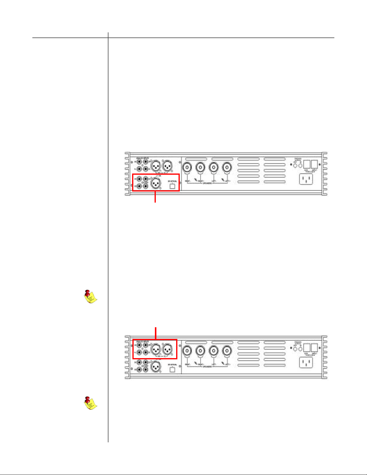
Digital input
The 2150 amplifier has 5 digital inputs:
- three RCA (S/PDIF) ( D1, D2, D3)
- one AES/EBU (XLR) (D4)
- one T osLink (S/PDIF) (D5)
All of the digital inputs support PCM audio data with sampling rates from 32kHz to
96kHz /16-24 bits, however , the AES/EBU and RCA/coaxial inputs support up to
192kHz.
Digital Input Section
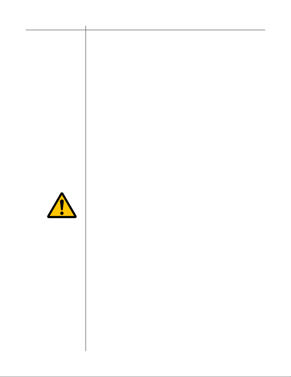
Analog input
(optional ADC module)
The 2150 amplifier has 3 stereo analog inputs whith the optional ADC module installed:
- two analog stereo single ended (RCA) (A1, A2)
- one analog stereo balanced (XLR) (A3)
NOTE: A/D conversion is always performed at 24-bits/192kHz.
Analog Input Section
NOTE: The optional ADC module is required for analog inputs.
9T act Audio
Page 10

M/S 2150 Connections
Digital output
The 2150 amplifier has a digital pass through. The digital input signal is passed to the
digital output without processing or volume control. The sampling rate is the native
sampling frequency of the input.
NOTE: that this output is not active when analog input is selected.
Digital Output
CAUTIONCAUTION
RS-232 interface
ports
The M/S 2150 has two RS232 interface ports:
- INPUT
- AUX
Use the “INPUT” port for communication with your T act master controller or Personal
Computer.
Use the “AUX” port to connect to TacT digital amplifiers.
RS-232 Interface Ports
10 T act Audio
Page 11

M/S 2150 Connections
Trigger output s
AC mains input
The M/S 2150 has a trigger “IN” and “OUT” to provide on and standby control
from a trigger device and to pass the trigger signal to another device.
Trigger Connectors
Connect the M/S 2150 to the AC mains wall socket.
CAUTION: Use the supplied IEC mains cable, or a 3-prong grounded cable only.
Speaker output
(normal operation)
Digital Output
The 2150 amplifier has one pair of high quality WBT speaker terminals. These terminals will accept both spade- and banana-plugs. When connecting your speakers,
please make sure that the RED/HOT terminal is connected to your speakers’ POSITIVE terminal and the BLACK/COLD terminal is connected to your speakers’ NEGATIVE terminal.
RIGHT
SPEAKER
+ -
LEFT
SPEAKER
+ -
11T act Audio
Page 12

M/S 2150 Connections
Speaker output
(Biamped operation)
Horizontal Biamping
If you are using two or more 2150 amplifiers, and your speakers allow for multiamping, you can configure the system to run in biamped or even tri-amped mode etc.
This type of setup allows for one amplifier channel to drive a specific driver or frequency region. The most commonly used setup is biamped (two channels to each
speaker: high and low). The following are two examples of making a biamped connection:
LEFT
SPEAKER
HIGH
LOW
CAUTIONCAUTION
RIGHT
SPEAKER
HIGH
LOW
12 T act Audio
RIGHT
SPEAKER
HIGH
+ -
LOW
+ -
LEFT
SPEAKER
HIGH
+ -
LOW
+ -
Page 13

M/S 2150 Connections
Vertical Biamping
LEFT
SPEAKER
HIGH
LOW
RIGHT
SPEAKER
HIGH
LOW
RIGHT
SPEAKER
HIGH
+ -
LOW
+ -
LEFT
SPEAKER
HIGH
+ -
LOW
+ -
13T act Audio
Page 14

6
6
6
6
6
6
6
6
6
6
6
6
6
6
6
6
6
M/S 2150 Connections
Biamping - continued
When two or more 2150 amplifiers are configured in a bi-/tri-amped setup, both the
signal and the RS232 TacT System Bus must be daisy chained between the amplifiers.
The same signal flow is applicable for both horizontal and vertical bi-amping.
From source
Digital signal
(coax/SPDIF)
Digital signal
(coax/SPDIF)
CAUTIONCAUTION
AMP-1
From RCS2.0S, RCS2.2X or
TCS mkII *Optional
RS232
RS232
AMP-2
Digital signal
(coax/SPDIF)
23456789012345678901234567890121234567890123456789012345678901212345
23456789012345678901234567890121234567890123456789012345678901212345
23456789012345678901234567890121234567890123456789012345678901212345
23456789012345678901234567890121234567890123456789012345678901212345
23456789012345678901234567890121234567890123456789012345678901212345
23456789012345678901234567890121234567890123456789012345678901212345
23456789012345678901234567890121234567890123456789012345678901212345
23456789012345678901234567890121234567890123456789012345678901212345
23456789012345678901234567890121234567890123456789012345678901212345
23456789012345678901234567890121234567890123456789012345678901212345
23456789012345678901234567890121234567890123456789012345678901212345
23456789012345678901234567890121234567890123456789012345678901212345
23456789012345678901234567890121234567890123456789012345678901212345
23456789012345678901234567890121234567890123456789012345678901212345
23456789012345678901234567890121234567890123456789012345678901212345
23456789012345678901234567890121234567890123456789012345678901212345
23456789012345678901234567890121234567890123456789012345678901212345
AMP-3 - ONL Y PRESENT IN TRI-AMPED SETUP
RS232
M2150 & S2150
Configurations
14 T act Audio
With its advanced DSP control, the M/S 2150 can enable digital crossovers
(high-and low-pass) making it is possible to configure the 2150 amplifiers to
virtually any system.
Examples of how a T acT active system can be configured:
1) Active two-way. The M2150 operates as master amp (control unit) and the
S2150 operates as slave amp. M2150 has a DSP-based high-pass filter and
drives the high-section of the 2-way loudspeaker. S2150 has a low-p ass filter and
drives the bass-section.
2) Active three-way. The Tact RCS operates as master pre-amp and the three
S2150 operates as slave amps. The top S2150 has a DSP-controlled high-pass
filter and drives the tweeter section. The middle S2150 has a High- and low-pass
filter and drives the midrange section. The bottom S2150 has a low-pass filter
and drives the bass section.
Page 15

Front Panel Controls
The front panel controls on the 2150 amplifier will allow you to control all of the
amplifiers main features. All secondary options are controlled with menus using the
remote control or the supplied software. The exclusive “TacT wheel” is the master
volume control. (The wheel is only available on the M2150)
ON/OFF
Master volume
MuteMaster VolumeDigital Input Selector
ON/OFF Switch
Analog Input Selector
Input Display
Display
Volume Level
Use the “ON/OFF” switch to toggle between ON and OFF operation.
(Standby mode can be only selected only through the remote control)
The master volume is controlled by turning the large volume wheel. The green numbers on the left side of the wheel will change as you turn the wheel - this is your
master volume level indicator. (The wheel sensitivity, maximum volume and other
settings can be found in the “OPT” menu.)
Mute
Digital
input selector
Analog
input selector
Use the “MUTE” button to mute or un-mute during playback. The master level indicator will switch to “--” in Mute mode. You can still adjust the master volume while the
unit is in Mute mode - the master level indicator will briefly indicate the level, then
switch back to “--” mute indicator
Press the “DIGITAL” button to select the digital input. This is a toggle switch, and
pressing it multiple times will toggle through all of the five digital inputs. The selected
input will be displayed in the input display portion of the display screen.
Press the “ANALOG” button to select the ANALOG input. This is a toggle switch, and
pressing it multiple times will toggle through all of the three analog inputs. The
selected input will be displayed in the input display portion of the display screen.
NOTE: The optional ADC module is required for analog inputs.
15T act Audio
Page 16

Remote Control
The remote control is used to access the front panel display controls and menus.
CAUTIONCAUTION
11
12
1
4
7
9
2
3
5
6
10
8
16 T act Audio
Page 17

Remote Control
1 - ST ANDBY
The ST ANDBY button will turn the M/S 2150 “ON” or it will place it into “STANDBY”
mode. When in standby mode, the unit is placed into a low power “idiling” state.
The standby button is also used to save changes that were made in the menu
editing parameters. By placing the unit into standby the current settings are
saved.
2 - DIGIT AL
The DIGIT AL button will scroll sequentially , allowing the selection of one of the 5
digital inputs.
3 - ANALOG
The ANALOG button will scroll sequentially, allowing the selection of one of the 3
analog inputs.
4 - CORRECTION block
The CORRECTION block buttons are inactive with this unit.
5 - MENU
The MENU button will switch the front panel display from the status screen to the
main menu screen.
6. VIDEO
The VIDEO button is inactive with this unit.
7. UP
The UP navigational button is used to select menu options and/or change their
values.
8. DOWN
The DOWN navigational button is used to select menu options and/or change their
values.
9. LEFT
The LEFT navigational button is used to select menu options and/or change their
values.
10. RIGHT
The RIGHT navigational button is used to select menu options and/or change their
values.
11. ENTER
The ENTER button will select the menu option currently marked by the blinking
cursor or is used to enter an edited parameter .
12. VOLUME Block
The VOLUME block consists of three buttons.
The “MUTE” button will mute/un-mute all enabled channels.
The “UP” button will increase the master volume level
The “DOWN” button will decrease the master volume level.
17T act Audio
Page 18

Front Panel Display
Main screen
MAIN menu
When the 2150 amplifier is turned ON and the system loading sequence has completed, the amplifier will display the normal operating main screen.
Main Screen :
1
CAUTIONCAUTION
INPUT: CD/Transport
-17.9 dB Fs= 44.1
2
1 - Name for input selection
2 - Master level in dB
3 - Input sampling frequency indicator.
The Main menu of the M/S 2150 has three pages of general menu selections.
Main Menu :
3
Saving Menu
Settings
DELAY LEVEL ADC
CRO TRIG DISPL->
<- OPT InOut POL
REM COMM ADDR ->
<- LOCK GAIN
The remote control is needed to enter the amplifiers Menu selection pages. Press
the “MENU” button to enter the amplifiers menu section. Use the “LEFT” and
“RIGHT” navigational buttons to highlight an option with the selection cursor and to
proceed to a new page. To enter a highlighted option press the “ENTER” button.
Once you are in a menu option Use the “MENU” button to go back one step (from
sub-menus) or to return to the main operating screen.
Custom settings that are made to any of the menu selections may be saved by
placing the M/S 2150 into standby mode. If you make changes to any of the menu
items and turn the unit off before placing it into standby mode all settings will be lost.
To place the M/S 2150 into standby mode press the red “STANDBY” button on the
remote control.
18 T act Audio
Page 19

Front Panel Display
DELA Y menu
The Delay menu controls the system’s time alignment. The system’s time alignment can be adjusted by changing the delay time for the left and right outputs independently .
.
Delay Menu :
LEFT RIGHT
0.00 0.00 msec
1
1 - Left and Right channel independent delay time settings.
Use the “LEFT” and “RIGHT” navigational buttons to highlight an option and use the
“UP” and “Down” buttons to change its value .
LEVEL menu
The Level menu controls channel balancing. You can adjust the system’s balance by changing the attenuation for the left and right output signals independently.
Level Menu :
LEFT RIGHT
0.0 0.0 dB
1
1 - Independent Left and Right channel level settings.
Use the “LEFT” and “RIGHT” navigational buttons to highlight an option and use the
“UP” and “Down” buttons to change its value .
19T act Audio
Page 20

Front Panel Display
ADC menu
(ADC module optional)
The M/S 2150 may be equipped with an optional state of the art Analog to Digital
Converter. To further enhance the converter’s performance, the system offers two
selectable gain values for the ADC input stage. These two values may be assigned to
each input independently .
ADC Menu :
3
GAIN: LOW IN:2
CAUTIONCAUTION
2
LOW HIGH
1
1 - Assignable gain values.
2 - Input channel currently selected.
3 - Active gain setting for selected input channel.
LOW = -6.0dB in reference to 0.0dB. Input sensitivity: 2.2 volt
HIGH = 0.0dB in reference to 0.0dB. Input sensitivity: 4.4 volt
Use the “UP” and “DOWN” navigational buttons to scroll through the available options
and press the “ENTER” button to activate the currently displayed selection. To select
an analog Input (2) use the “ANALOG” selector button found on the M/S 2150 front
panel or on the remote control to scroll to the input you would like to edit.
CRO menu The M/S 2150 can apply user selectable crossovers to the outputs. The default
setting is set to “OFF” with no crossovers applied. For your convenience there are a
total of 10 default crossover selections pre-loaded for use with most biamped
systems. If a different crossover is desired, there are other options using the P.C.
software included with the unit.
CRO Menu :
3
CRO : L65, H65, 10
4: L65, H65, 10 *
1
1 - Crossover selections.
2 - Active Crossover selection.
3 - Active Crossover selection.
Example : Option #4 - 10th order lowpass @ 65Hz + 10 highpass @ 65Hz
(See the “InOut” menu for more information about output settings used with
crossover configuration)
Use the “UP” and “DOWN” navigational buttons to scroll through the available
options and press the “ENTER” button to activate the currently displayed
selection.
2
20 T act Audio
Page 21

Front Panel Display
TRIG menu
The trigger menu is used to control the behavior of the 2150 amplifier when a trigger
signal is detected. When the input trigger is set to “ON” and a trigger signal is de-
tected the amplifier will turn ON. The amplifier will stay in or switch to “STANDBY”
mode if there is no trigger signal detected. When the input trigger is set to “OFF”
the unit will not respond to a trigger signal however, the trigger signal will still be
passed through the Trigger OUT terminal on the rear panel.
TRIGGER Menu :
2
TRIGGER INPUT: OFF
OFF ON
1
1 - Trigger input selections.
2 - Active trigger input setting.
Use the “LEFT” and “RIGHT” buttons to highlight the desired option and select it by
pressing the “ENTER” button.
DISPL menu
(Display)
The display menu controls the display Time-Out feature. This option is used to turn
the front panel display “ON” or “OFF”. When this option is set to “ON” the front
panel timer will turn the front display off when the front panel has not been accessed for 10 seconds. When this option is set to “OFF” the display will remain lit
whenever the unit is on. To wake the display, simply turn the wheel or push any
button on either the front panel or the remote control.
Display Menu :
2
Display Timeout OFF
OFF ON
1
1 - Display Timeout selections.
2 - Active Display Timeout setting.
Use the “LEFT” and “RIGHT” buttons to highlight the desired option and select it by
pressing the “ENTER” button.
21T act Audio
Page 22

Front Panel Display
OPT menu
(Options)
The options menu is designed to control the systems maximum signal level
“MAXLEV”, signal detection threshold “DTHR” and wheel speed “WH”.
CAUTIONCAUTION
NOTE: Wheel speed is only available on the M2150.
Options Menu :
MAXLEV DTHR WH
+12.0 -6.0 dB 5
1 32
1 - Maximum Level setting.
2 - Detection setting.
3 - Wheel speed setting.
- Max Level controls the system’s maximum signal level.
For example: if this option is set to -3.0 dB, the volume control
and output can not go above -3.0 dB.
- Detection sets the signal detection threshold. If the absolute
value of the Left or the Right channel signal goes above this
threshold the red signaling dot will be displayed on the front
panel bellow the master volume display. This feature can be used
to indicate signal presence on either channel or to indicate near
clipping condition. To use it as signal presence indicator set Detec-
tion to a value close to -90.0 dB. To use it as near clipping indicator
set Detection to a value close to 0.0 dB.
22 T act Audio
- Wheel option sets the wheel sensitivity. The maximum speed is 10 and
minimum speed is 1. For example if the speed is set to 1, the volume increase is
slower than if set to 10. To turn the wheel off, set the speed setting to “OFF”.
This setting is located one step below “1” the minimum speed.
To select/highlight an option use the “LEFT” or “RIGHT” buttons. To modify a selected option use the “UP” and “DOWN” buttons.
Page 23

Front Panel Display
INOUT menu This InOut menu is used to set the channel output configuration for the M/S 2150.
NOTE: For vertical Biamping, the source menu option should be set to
“L”+”L” for the amplifier that drives the LEFT speaker, and “R”+”R” for the
amplifier that drives the RIGHT speaker.
POL menu
(Polarity)
InOut Menu :
2
OUTPUT: L R
SOURCE: L R *
1
1 - Source selections for output.
2 - Fixed output speaker posts.
3 - Active source setting.
Scroll through the available options with the “UP” and “DOWN” buttons and select it
with the “ENTER” button.
The polarity menu is used to set the polarity independently for each channel.
Each channel can be set to + (0) or - (inverted).
Polarity Menu :
3
LEFT RIGHT
+ +
1 2
1 - Left channel polarity setting.
2 - Right channel polarity setting.
To select/highlight an option use the “LEFT” or “RIGHT” buttons. To modify a selected option use the “UP” and “DOWN” buttons.
23T act Audio
Page 24

Front Panel Display
REM menu
(Remote)
The remote menu allows for disabling or enabling the remote control. Once the remote control is disabled the unit can only be controlled from the front panel of the
unit. An alternate way to enable or disable the remote control is to press the front
panel “ANALOG” and “DIGITAL” button simultaneously - this can be used to
change the remote control state without entering the REM menu.
Remote Menu :
CAUTIONCAUTION
2
REMOTE CONTROL: ON
OFF ON
1
1 - Remote control settings.
2 - Active remote control setting.
Use the “LEFT” and “RIGHT” buttons to highlight the desired option and select it
with the “ENTER” button.
COMM menu
(Communication)
The communication menu allows for RS232 baud rate selection. By default the
2150 amplifier is set to a baud rate of 57600. However, some remote control systems may require a baud rate of 9600. The menu also contains the option to set
the M2150 as a master controller for a system with multiple 2150 amplifiers.
NOTE: MASTER control is only available on the M2150.
Communication Menu :
3
BAUD RATE: 57600
57600 9600 NORMAL
1 42
1 - 57600 baud rate setting.
2 - 9600 baud rate setting.
3 - Active baud rate setting.
4 - Master/Normal control setting. (M2150 ONLY)
Use the “LEFT” and “RIGHT” buttons to highlight the desired option and select it
with the “ENTER” button.
24 T act Audio
Page 25

Front Panel Display
ADDR menu
(Address)
LOCK menu
The address menu allows for the setting of the “address” for the unit. The default
address setting is “001”. If multiple amplifiers are used together, dif ferent addresses
will allow individual control of each amplifier.
Address Menu :
2
CURRENT ADDRESS: 001
ADDRESS: 001
1
1 - Address settings.
2 - Active address setting.
Use the “UP” and “DOWN” navigational buttons to select the desired system address and then press the “ENTER” button to select it.
The lock menu allows a lock to be set to prevent entering the M/S 2150 editing
menus and the changing of the selected input without unlocking the 2150 with the
lock code. By default the 2150 is unlocked and all menus can be accessed and
inputs can be changed without entering a lock code. When the unit is locked, the
only menu option that can be entered is the “LOCK” menu to unlock the unit.
Once the lock code is entered you will be able to use the 2150 menus until the
lock code is entered again to lock the 2150.
Lock Menu :
2
M/S 2150 : LOCKED
PASSWORD : 0000 SET
1
1 - Lock code.
2 - Active lock state.
3 - Set button.
T o lock or unlock the M/S 2150 enter the lock code “1-2-3-4” by using the “LEFT”
and “RIGHT” remote control buttons to select each digit and use the “UP” and
“DOWN” buttons to select the desired number from 0 to 9 . Once the code is entered select the “SET” option and then press the “ENTER” button to unlock or lock
the unit. The active lock state will be displayed in the active lock state portion of
the screen.
3
25T act Audio
Page 26

GAIN menu
The gain menu allows for an increase in the overall volume level of the amplifier.
There are four gain settings that are available: 0dB, 6dB, 12dB, and 18dB.
The amplifier will increase its overall gain by the amount set in the “Gain” setting.
For example if “0dB” is selected the amplifier will output +0dB at maximum volume
(99), if “18dB” is selected the amplifier will output +18dB at maximum volume (99).
CAUTIONCAUTION
Gain Menu :
Gain
12 dB
1
1 - Active gain setting.
T o edit the “ Gain” setting use the “UP” and “DOWN” buttons to select the desired
gain level setting 0dB, 6dB, 12dB, and 18dB. The gain setting that is displayed is
the active gain setting.
26 T act Audio
Page 27

T acT M/S2150 Software
The M/S2150 is more than just an amplifier. With powerful features such as level
balancing, time alignment, and assignable electronic crossovers, you can customize and build the amplifier system that you need, whether your system is biamped,
triamped or more. Each of Tact’s amplifiers employ an RS232 in and out connection for control from a Tact master controller. Complete instructions for using the
2150 software can be found in the online help available in the software.
System requirements
Software Installation
Y our computer system must meet the following requirements:
- An IBM compatible PC with Pentium 100 MHz, 64 MB Ram & 100 MB
free hard disk space or better
- Microsoft Windows 98, ME, 2000 or XP
- Operating system regional setting must be set to “English(United St ates)”
- Microsoft Windows-compatible graphics-card and monitor with screen
resolution 800x600 or better
- CD-ROM drive
- Microsoft windows compatible 2- or 3- button mouse
- Standard RS-232 serial port with DB-9 connectors
Follow the steps below to install the M/S2150 Room Correction Software:
1 - S tart windows and insert the TacT software CD into your CD-ROM drive.
2 - Double-click on the “My Computer” icon on the desktop.
3 - Double-click on the CD icon to launch the CD browser .
4 - Double-click on “Tact 2150 vx.x.exe” and follow the instructions.
After the installation you will have the option to launch the M/S2150 software. If
you would like to launch the program at this time when prompted, select “Launch
T acT-2150” and the software will start. You should now see the M/S2150 System
main-screen.
Start The M/S2150
software
T o st art the software go to the Windows “Start” menu, select “Programs” then
“TacT-2150” and click on the “TacT-2150” icon. Y ou should now see the M/S2150
System main screen.
27T act Audio
Page 28

TacT M/S2150 Software
Connect your
M/S2150 to your
Computer
Y our M/S2150 must be connected to your computers serial port in order for it to
communicate with your computer when you run the M/S2150 software. Please follow the steps below to connect your M/S2150 to your computer .
1 - Connect the RS 232 “Input” jack on the back of the M/S2150 to your
computers serial port using the supplied cables and adapters. Y our computer
must have a standard RS 232 serial port with a DB 9 connector .
NOTE: If you have any other T act digital amplifiers please disconnect their
RS232 connection at this time.
2 - Turn on your M/S2150.
3 - Turn on your computer and start the M/S2150 System Software.
NOTE:Y ou may receive a communication error message. Please close the mes-
sage window and proceed to the next step.
4 - Select the “Com” button on the main software screen to open the communica-
tion window.
5 - Under the Operating Mode select “Connect”.
6 - Under the COM Port section select “COM1”. If you receive an “invalid
port number” message please try selecting each of the port selections until
you do not receive this message. If you receive this message on all COM ports
you may not have a COM port installed on your computer . Please refer to your
computer manufactures documentation for help to install a COM port.
CAUTIONCAUTION
28 T act Audio
7 - To verify that M/S2150 is properly connected to the host computer clickon
the “Start” button to perform the communication test. If everything is
functioning properly you should see the results below. Press the “Stop”
button after about 15 seconds to stop the test.
Rx Buf should display “0”.
Count should have counted in increments of 100.
Err Count should be “0”.
If the results are as above select the “Close” button to close the communication
window. Your M/S2150 is now connected to your computer.
If the results are not as above please go back to step number 6 and select
another COM port. Then repeat step 7.
NOTE: If you are still are not passing the communication test you may not
have a COM port installed on your computer or you may have another device such as a modem or hand held PC that may be sharing the COM port
on your computer. If you have a other Tact equipment attached it may be
set to the same address. The M/S2150 requires a valid COM port that is not
being used by any other devices.
NOTE: You will only have to select the communication port once. The next
time you run the M/S2150 correction software it will remember your settings.
Page 29

Specifications
Power (RMS. per channel) 8 ohm 2 x 150W
Power (RMS. per channel) 4 ohm 2 x 300W
Output current (peak, per channel) >50 A
Signal-to-noise ratio ( A-weighted) >110dB
Dynamic range (20 Hz - 20 kHz) >130dB
THD+N (all power levels 20Hz-20kHz) <0.01%
Digital resolution 16-24 bit
Linearity (-120dB) +- 0,2dB
Dimensions (WxHxD) 450x140x420 mm
17.7x5.5x16.5 in.
Weight (shipping) 18 kg / 37 lbs
29T act Audio
Page 30

TacT Audio, Inc.
201 Gates Road Unit G, Little Ferry – New Jersey 07643, USA
Phone: +1 201 440 9300 – Fax: +1 201 440 5580 – Email: info@tactaudio.com
www.tactaudio.com
 Loading...