

Page 1

Owner’s Manual
RCS 2.2 XP
Preamplifi er /
Dynamic Room Correction System
Page 2

Page 3
3
Tact Audio
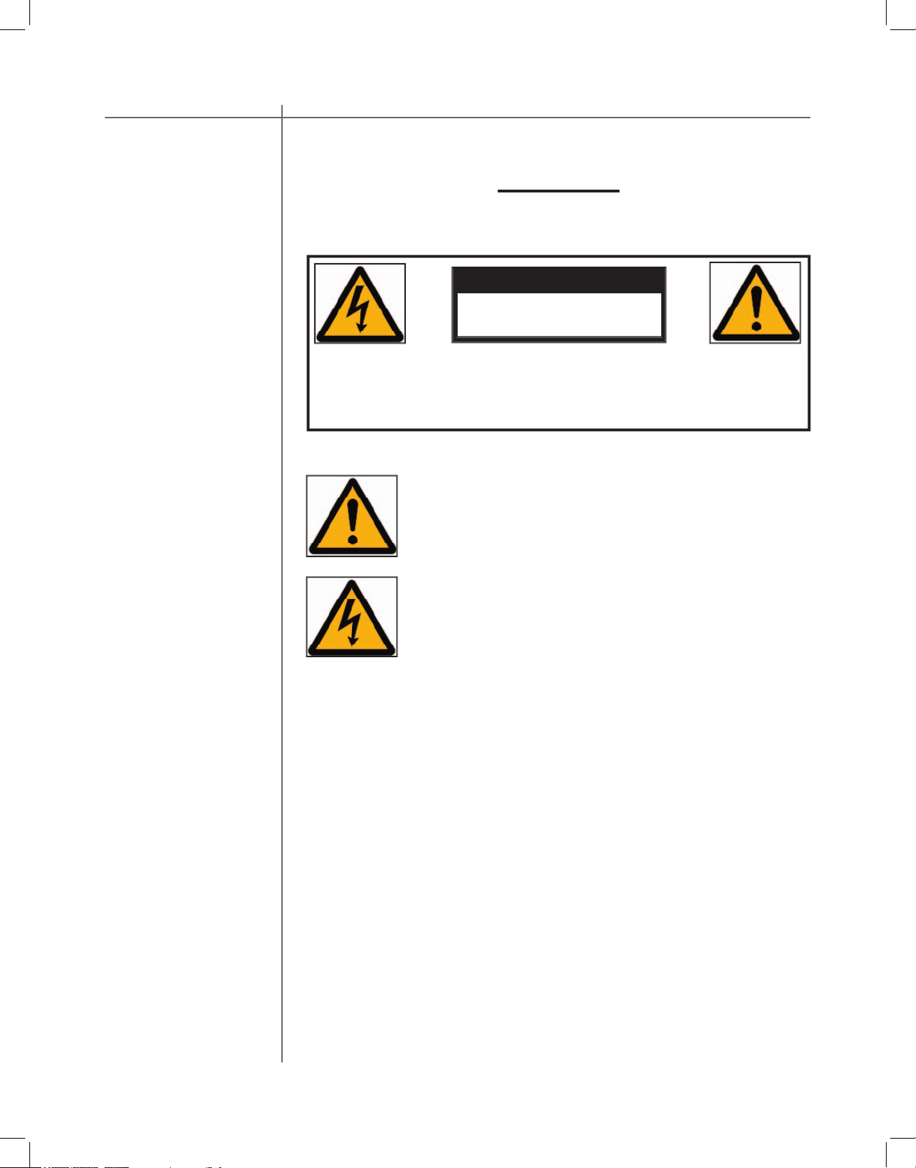
WARNING
TO REDUCE THE RISK OF FIRE OR ELECTRIC SHOCK, DO
CAUTION
The exclamation point within an equilateral triangle is intended to alert the
The lightning with arrowhead symbol within an equilateral triangle is
the product’s enclosure that may be of suffi cient magnitude to constitute
Page 4
CAUTIONCAUTION
4
Tact Audio
1. Read these instructions entirely before installing or operating this equipment.
2. Keep these instructions.
3. Heed all warnings.
4. Do not use this equipment near water or allow it to become wet.
5. Do not block any ventilation openings. Install in accordance with the manufacturer’s instructions.
6. Do not install near any heat sources such as radiators, heat registers, stoves,
or other appliances (including amplifi ers) that produce heat; doing so may
damage the unit and present a fi re hazard.
7. Do not defeat the safety purpose of the polarized or grounding-type plug. A
polarized plug has two blades with one wider than the other. If the provided
plug does not fi t into your outlet, consult an electrician for replacement of the
outlet to one that is polarized. To protect against electrical shock, match the
wide blade of the polarized plug to the wide slot in the outlet and fully insert
the plug.
8. Protect the power cord from being walked on or pinched, particularly at plugs,
convenience receptacles, and the point where they exit the equipment. Do not
use this unit with a damaged cord or plug.
9. Only use attachments/accessories specifi ed by the manufacturer.
10. Unplug this equipment during lightning storms or when unused for long periods of time.
11. Refer all servicing to qualifi ed service personnel.
1. Always unplug the unit from the electrical outlet before cleaning.
2. Do not use abrasive cleaners. Simply wipe the exterior with a clean soft cloth.
A small amount of nonabrasive cleaner may be used on the cloth to remove
excessive dirt or fi ngerprints.
The >note< symbol indicates information very useful or essential to daily
operation.
Page 5
Tact Audio
future upgrades or should you ever require service on your RCS 2.2 XP Pream-
_______________________
_______________________
_______________________
written consent of the Tact Audio Corporation.
The information contained in this document is subject to change without
Page 6

CAUTIONCAUTION
Tact Audio
TABLE OF CONTENTS
Main screen 28
30
MODE menu 31
ADC menu 32
DOUT FS menu 33
POL menu 34
TEST menu 34
DISPLAY menu 35
COMM menu 36
AMP menu 37
OPTIONS menu 38
LOCK menu 39
MSR menu 40
INFO menu 40
LEVELS menu 42
DELAYS menu 42
NAMES menu 43
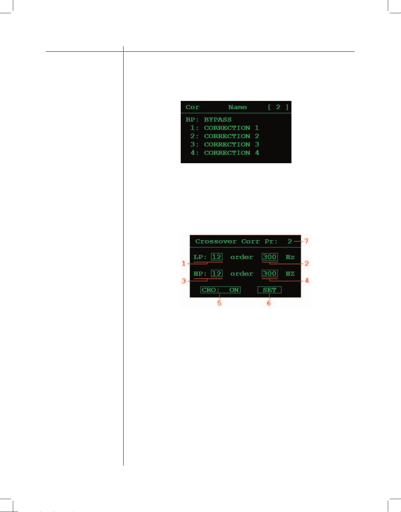
CRO menu 43
MSR menu 44
4
LINK option 47
TABLE menu 48
Page 7
Tact AudioTact AudioTact Audio
2.2
Carefully remove the RCS 2.2 XP and accessory kit from the carton and visually
check for shipping damage. Contact both the shipper and TacT Audio immediately
if the unit shows any sign of damage from rough handling. All TacT Audio equipment is carefully inspected before leaving our factory.
KEEP SHIPPING CARTON AND PACKING MATERIALS for future use or in the
unlikely event that the unit needs servicing. If this unit is shipped without the
original packing, damage could occur and void the warranty.
You should fi nd the following items in the accessory kit:
The RCS 2.2 XP is designed with an automatic switching power supply. It will oper-
The RCS 2.2X has three operating modes:
The unit is powered but all outputs are muted and the display
toggle between ON and STANDBY.
Page 8

Tact Audio
The RCS 2.2 XP has four times the processing power of the famous TacT RCS
2.0 and even better AD and DA conversion. This now combined with new features and a more user-friendly interface takes TacT Audio’s room correction to
new heights. The RCS 2.2 XP has no noise and extremely low distortion, yielding
amazingly transparent accurate sound. Every eff ort has been made to make this
preamplifi er the best that money can buy. Add to this the latest evolution of TacT
Audio’s room correction technology and the result is absolutely staggering.
TacT room correction technology has been praised by the press all around the
world. Comments like “Wholesale improvement in sound quality” have become
a standard phrase for reviewers describing the results that can be achieved with
TacT’s room correction. Now we have taken room correction technology even
further, not only in terms of processing power, but also in terms of the measurement and correction systems. The measurement is now done with a triple pulse
for each acquisition. This increases the measurement resolution in both the time
and frequency domains. Correction resolution is now four times higher than found
in the original RCS 2.0.
One of the most exciting features of the RCS 2.2 XP is its separate subwoofer
output. The RCS 2.2X P can be used with one or (preferably) two subwoofers. An
electronic crossover can be set with a frequency between 60 and 400 Hz and a
slope between 12 dB/octave and 60 dB/octave to split the audio signal between
the main and subwoofer outputs. The correction software aligns the sub-woofer(s)
with the main speakers in the time domain and in the frequency domain, for completely seamless integration surpassing even the best single-box systems.
CAUTIONCAUTION
With the RCS 2.2 XP, you can add subwoofers to an existing High End speaker
system for substantial sonic improvements. Preferably, the subwoofers should be
placed in the corners behind the main speakers. Corner placement of the subwoofers will yield much higher effi ciency with signifi cantly reduced low-frequency
distortion. But more importantly, the transfer of energy from the sub to the listening
position will be much more direct, resulting in vastly improved impulse response.
The room correction system will easily compensate for the frequency response
variations of the subs introduced by corner placement. It will delay the main
speakers for perfect time alignment to within 1/8 of an inch.
The RCS 2.2 XP off ers you the opportunity to add subwoofers to a system and
improve the transient response tremendously at the same. This contrasts sharply
with the normal result of adding subwoofers to a system: slow – undefi ned bass
with lots of frequency and time behavior problems. If the separate subwoofer
outputs are not used, then the RCS 2.2X will use all the processing power on the main
speakers.
Page 9

Tact Audio
True
Upgradeability
future interfaces.
features can be loaded through the RS232 port with fi rmware upgrades.
It is our
policy to offer software upgrades at no cost, and we therefore encourage you to
Page 10

CAUTIONCAUTION
Tact Audio
Dynamic Room Correction (DRC) ® is new technology developed by Tact Audio
Inc. over past two years. This groundbreaking brings the science and art of Room
Correction, and specifi cally Tact room correction products, to yet another level.
When we introduced our fi rst RCS system (the Tact-2.2 in the late 90’s) we were
fully aware that we were embarking on a long term research process in the new
exciting fi eld of room acoustics correction. As a result of this research effort we
brought to the market products such as Tact-2.0 S two channel RCS preamp, the
Tact-2.2 X two channel preamp with RCS on two main and two subwoofer channels, and the TCS MKII ten channel theater correction system. All these systems
offer RCS technology not found in any other product on the market. Our continued research combined with enormously valuable feedback from our customers
has resulted in this new technology that we named Dynamic Room Correction
(DRC)®.
Why do we call it Dynamic Room Correction (DRC)?
The reason we call it DRC is that the target curve used to compute correction fi lters dynamically changes with the master level control. In another words, for every
0.1 dB of level change the system uses a new target curve to compute room cor-
rection fi lters. What makes this dynamic is that all computations and adjustments
are done on the fl y without any interruption to the music you listen to.
Why do we need Dynamic Room Correction (DRC)?
It is well known fact that humans do not here all frequencies at the same level.
It is also known that our ears are more sensitive to frequencies between 2000
and 5000 Hz than to frequencies bellow 2000 Hz and above 5000 Hz. In addition to this our hearing sensitivity changes with sound pressure level (SPL). This
human hearing property was fi rst discovered and experimentally confi rmed by
Fletcher and Munson at Bell Laboratories in 1933 and later refi ned by Robinson
and Dadson in 1956. Their work resulted in a family of equal loudness curves
(contours), widely known as Fletcher-Munson equal loudness curves. A sample of
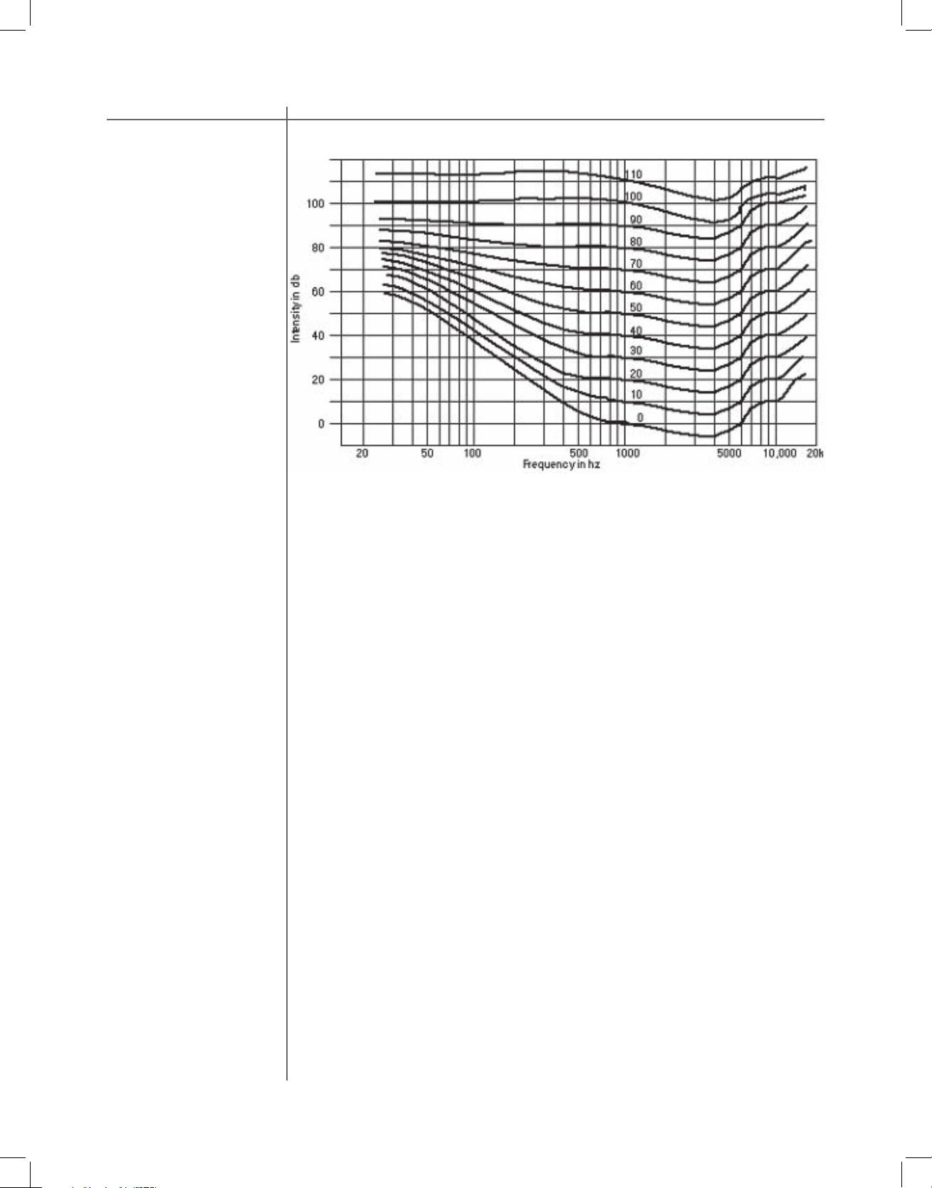
Fletcher-Munson loudness curves is shown in the fi gure bellow.
On the graph there are 12 curves numbered from 0 to 110. These numbers represent the loudness level in phons. A Phon is a unit used to describe the loudness
level of a given sound. The reason for introducing the loudness unit is that two
sounds with the same SPL (dB) do not necessarily have the same perceived loudness. Phon is equal to SPL in decibels at 1000 Hz. For example, 80 phons means
as loud as 80 dB, 1000 Hz tone.
Equal loudness curves represent the SPL that different frequencies need to have
in order to be perceived as two tones of equal loudness. For example, a 200 Hz
tone at SPL of 50 dB will have the same perceived loudness as a 1000 Hz tone at
SPL of 40 dB. In this case both 200 Hz and 1000 Hz tones have a loudness of 40
phons, and they both belong to the 40 phons equal loudness curve.
As it can be seen from the graph, in comparison to frequencies between 2000
and 5000 Hz, it is intrinsically harder for us to hear very low frequencies (below a
few hundred Hz) and to a lesser extent very high frequencies (above 7000 Hz). At
higher listening levels this difference gradually becomes smaller and smaller and
curves become fl atter.
Page 11
Tact Audio
Traditional Tact room correction systems use one target curve that allows for
full range 20-20,000 Hz room corrections. Once selected, the same target curve
(same set of correction fi lters) was used at all listening levels. This approach did
not take in account the fact that our sound perception, as described by FletcherMunson curves, is frequency and level dependent. Many of our customers have
realized this fact and they have used the nine correction presets (available on all
our RCS products) to program 2.0 S, 2.2 X and TCS MKII with nine different target
curves each corresponding to a different listening level. In this way they were able
to take into account the equal loudness curve effect by switching to new target
curves as the master level changes.
Thus for a number of reasons it is clear that we need a room correction system
that will perform room acoustics correction and at the same time dynamically
change the target curve (correction fi lters) as the system listening level changes.
How does it work?
Dynamic Room Correction (DRC) offers a very sophisticated way of handling a
multi target curve approach to solving equal loudness curve problem. The system
is based on one reference target curve and eight additional target curves called
dynamic target curves. The reference target curve is used to perform basic reference room correction. Dynamic target curves are labeled 0, -6, -12, -18, -24, -30,
-36 and –42 dB and are combined with the reference target curve to obtain the
fi nal target curve used to calculate correction fi lters.
For example, if the master level reads –10.3 dB (89.6 on the relative readout) the
system will use the –6 dB and the –12 dB dynamic target curves and by interpolation will calculate a target curve corresponding to –10.3 dB. After that the system
will combine the 10.3 dB target curve with the reference curve to obtain the fi nal
target curve that is then used to calculate the correction fi lters. New correction
fi lters are loaded into the signal path as the music is playing and the new correction takes effect in a split of a second. The same process repeats again for any
new master level setting.
Page 12

CAUTIONCAUTION
Tact Audio
ROOM CORRECTION
Tact-2.2 XP can now perform room correction automatically from the 2.2 XP front
panel user interface, without the need for an PC software.
The automatic room correction feature is designed to perform the entire room correction process without using a PC interface. The Tact-2.2 XP has suffi cient DSP
processing power to perform room measurement, crossover fi lter design, target
curve generation and correction fi lter calculation. The entire process is controlled
from the 2.2 XP front panel DRC-RCS menu. Target curve and crossover fi lter
adjustments can be made on the fl y while the music is playing. Users can, for example, specify a boost at low frequencies or a roll-off at high frequencies. Values
of the ‘low’ and ‘high’ frequencies can also be adjusted.
PC based room correction requires that the 2.2 XP is connected to the RS232 port
of a PC. PC software is used just as a GUI (graphical user interface) to provide
the user with a graphical presentation of the correction process. After the room
response measurement is completed, the room frequency response for all measured channels can be displayed on the screen. Crossover fi lters and actual correction fi lters can be viewed. The displayed graphs provide valuable information
that helps users design their own optimum target curve.
The Tact-2.2 XP memorizes two sets of target curves: computer generated and
automatically generated target curves. When the automatic feature is turned OFF,
the 2.2 XP will use a computer generated set of target curves. When the automatic
feature is turned ON, the 2.2 XP uses target curves generated by the 2.2 XP front
panel automatic correction feature.
When the 2.2 XP is connected to a PC and the automatic feature is enabled, automatically generated target curves will be uploaded into the RCS/DRC screen.
The curves can than be saved or modifi ed. Modifi ed curves can than be loaded
back into the 2.2 XP. However, the uploaded curves will not take effect until the
automatic feature is disabled. Any target curve uploaded to 2.2 XP is saved as
a PC generated target curve and takes effect only when the automatic feature is
disabled. In another words, if a target curve is to be modifi ed by the PC software,
the automatic correction feature has to be disabled.
This following describes the automatic room correction process for all 2.2 XP
operating modes.
Page 13
Tact Audio
This operating mode assumes a stereo system consisting of two main channels
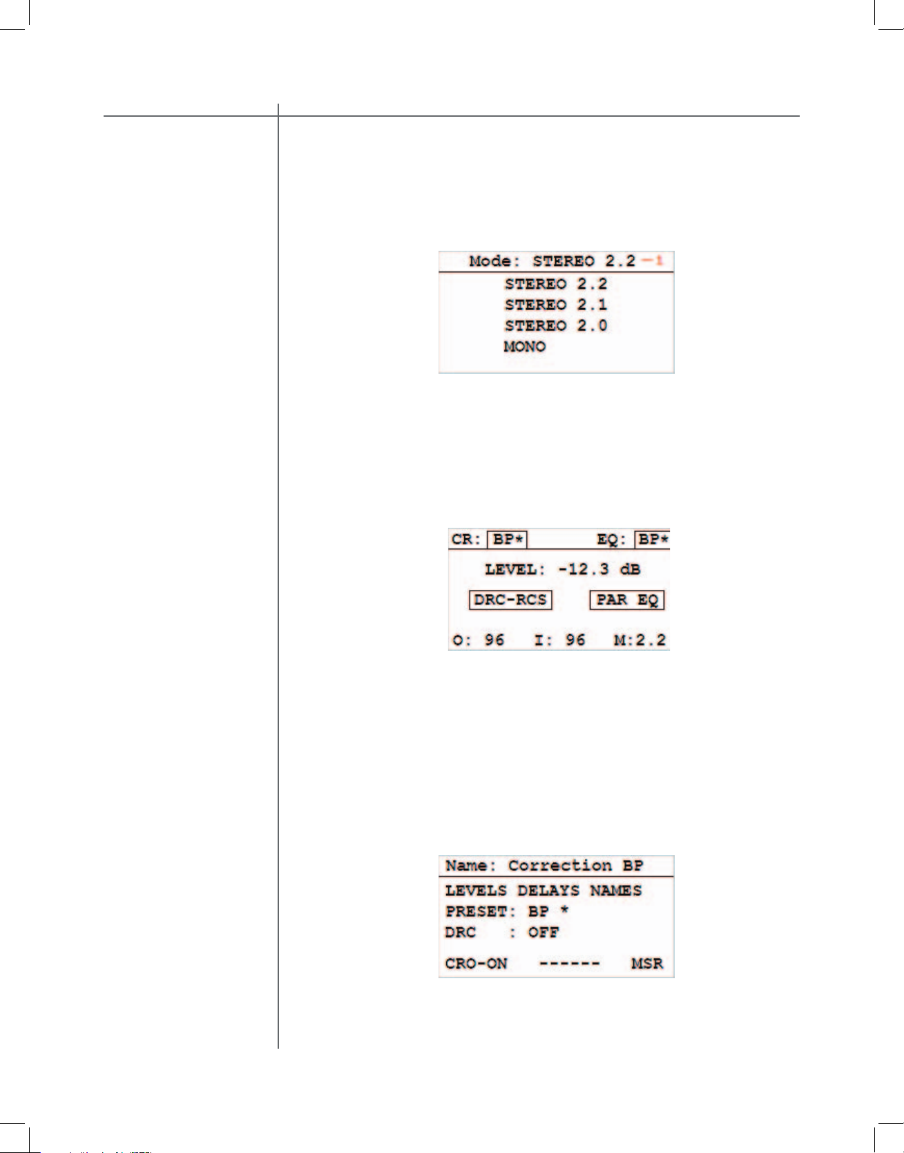
and two subwoofers. To select 2.2 mode from the main screen, click on the MENU
button, and then select the MODE menu. In MODE menu, click on the STEREO
2.2 option. This will select 2.2 mode and will display it on top of the screen (1)
Fig.1.
Fig. 1. Mode menu. 2.2 mode selection is displayed in the upper left corner (1).
To perform 2.2 mode automatic room correction go through the following steps:
1. Correction Bypass. Place 2.2 XP in correction bypass mode. You can place
2.2 XP in bypass mode by pressing on the BP remote control button or by using
the front panel controls.
Fig. 2. Tact-2.2 XP main screen. Note a ‘*’ next to BP. It indicates that BP – bypass
mode is selected.
2. Crossover Filters Off. Make sure that crossover fi lter option is set to OFF. It
is important that all measurements are performed without any crossover fi ltering.
If your loudspeakers have built in electronic crossover fi lters, make sure that they
are disabled. If crossover fi lters could not be disabled, set the subwoofer crossover
fi lter to its highest frequency and main channel to its lowest cut off frequency.
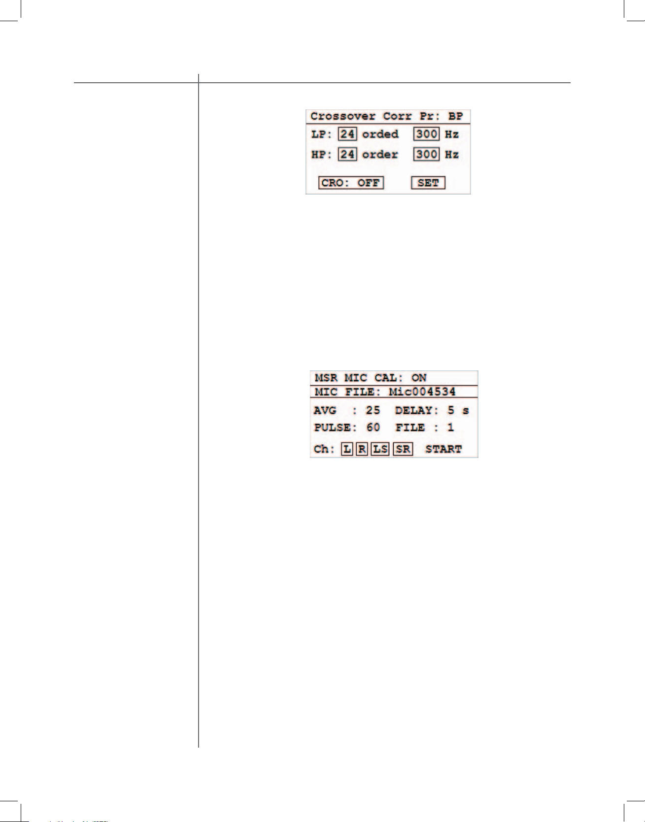
To disable crossover fi lters enter the
RCS-DRC menu and select the CRO-
ON(OFF) option in Fig.3 to enter Crossover screen Fig. 4.
Fig. 3. RCS-DRC screen.
Page 14
CAUTIONCAUTION
Tact Audio
Fig. 4. Crossover menu. CRO: OFF indicates that crossover fi lters are disabled
Crossover fi lters can be turned OFF from the front panel crossover menu (Fig. 4).
Place the screen cursor over the CRO: ON menu option and then press the enter
button (click) until it displays CRO: OFF, and then click on SET option.. Please
note that any change made on this screen does not take effect until you click on
the SET option.
Click on the MENU button to go back to the DRC-RCS screen, Fig. 3.
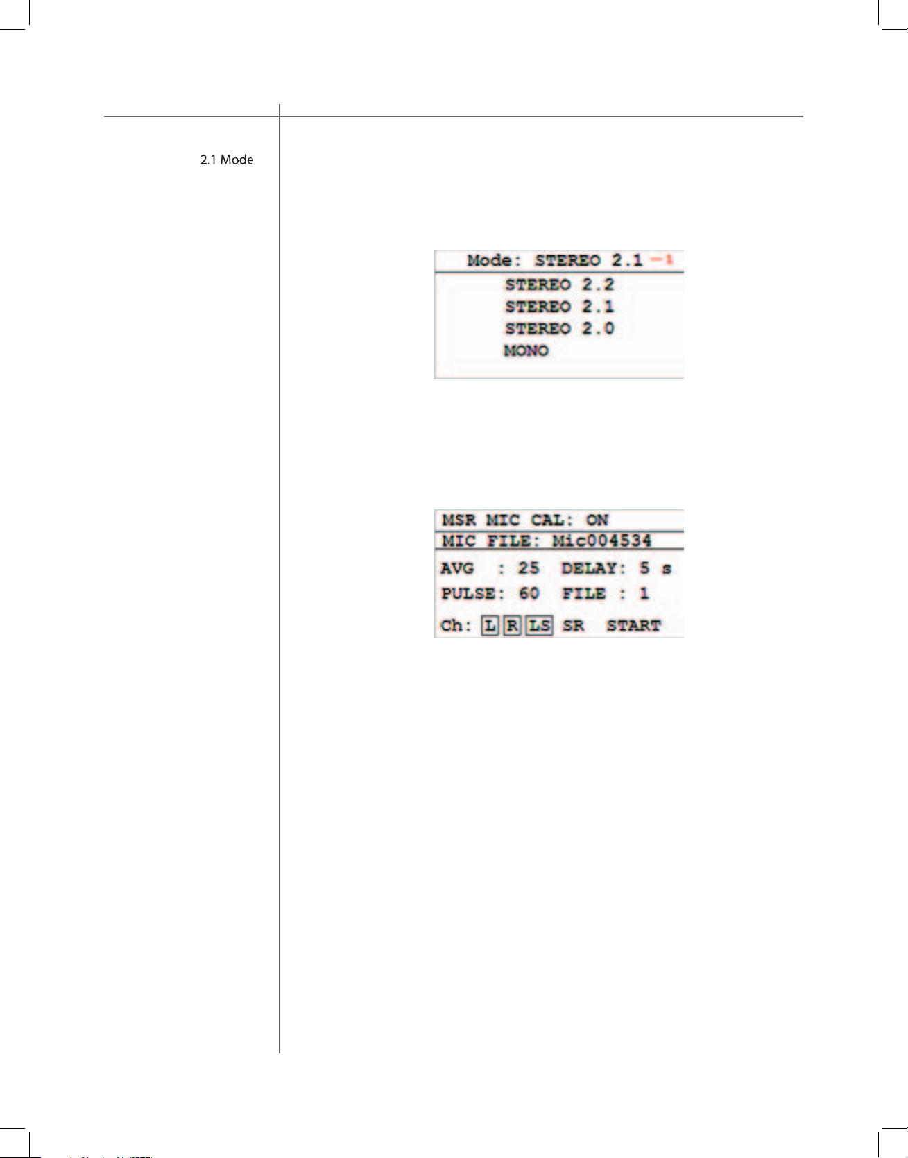
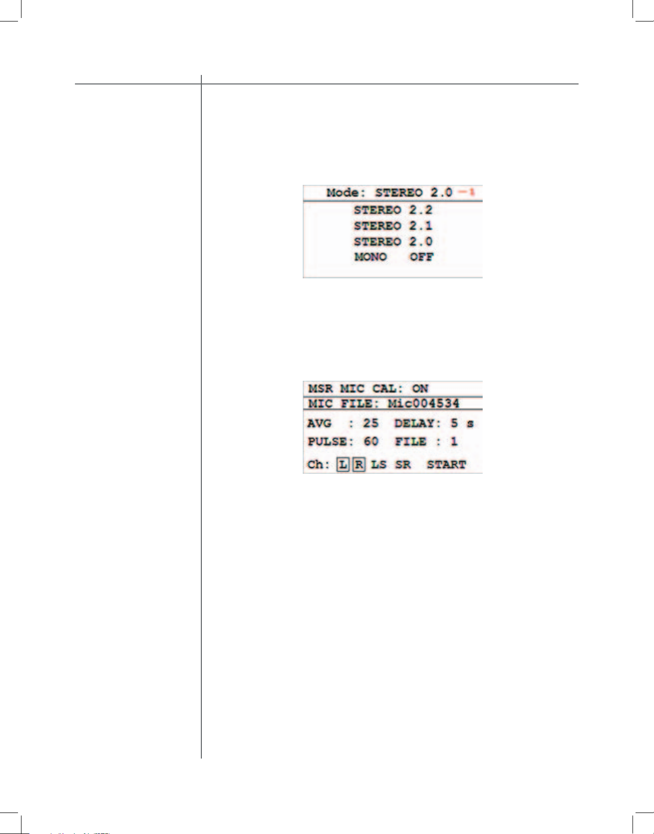
3. Measurements. To perform room response measurements, select the MSR
menu option to display the measurement screen (Fig. 5).
Fig. 5. Measurement screen.
The 2.2 XP is factory confi gured to measurement parameters as displayed in Fig.
5. The MSR MIC CAL option should be turned ON and the MIC FILE fi eld should
display the microphone serial number as printed on your microphone
MSR MIC CAL. When this option is set to ON, the room correction algorithm will
apply the microphone calibration fi le to the measurement data. When this option
is set to OFF, the microphone calibration fi le is ignored.
MIC FILE. This fi eld displays the microphone fi le name used to perform microphone calibration. The microphone calibration fi le data is saved in 2.2 XP internal
memory. For more details on how to transfer microphone calibrations fi le to 2.2 XP
memory, please refer to the Microphone section of the PC software manual.
AVG This is a very important measurement parameter. It equals the number of
measurements that are averaged prior to being saved. The averaging process
reduces the effects of random environmental noise. Typical Average values go
from 10 to 30.
Page 15
Tact Audio
DELAY. If you do not want to be in the room while measurement is in progress,
set this parameter to a few seconds to allow you to exit the room. For example, if
DELAY = 10 the system will wait for 10 seconds before it starts pulsing.
PULSE. This parameter sets the relative level of the output measurement pulse.
Minimum level is 1% and maximum level is 100%.
FILE. Use this option to assign a File number to the measurement you are just
about to perform. At the end of the measurement process, the measurement data
for all four channels will be saved in the selected File number. Tact-2.2 XP supports up to seven measurement fi les. In another words you can save up to seven
different measurements in 2.2 XP internal memory.
Use L, R, SL and SR options to select (enable) a channel for measurement.
Channels are labeled as L for left, R for right, SL for subwoofer left and SR for
subwoofer right channel. Selected (enabled) channels are marked by a rectangle.
To select or deselect a channel place the cursor over desired channel and press
ENTER button.
In most cases, factory presets are optimum and users can proceed directly with
peforming actual measurements. To initiate the room measurement process, click
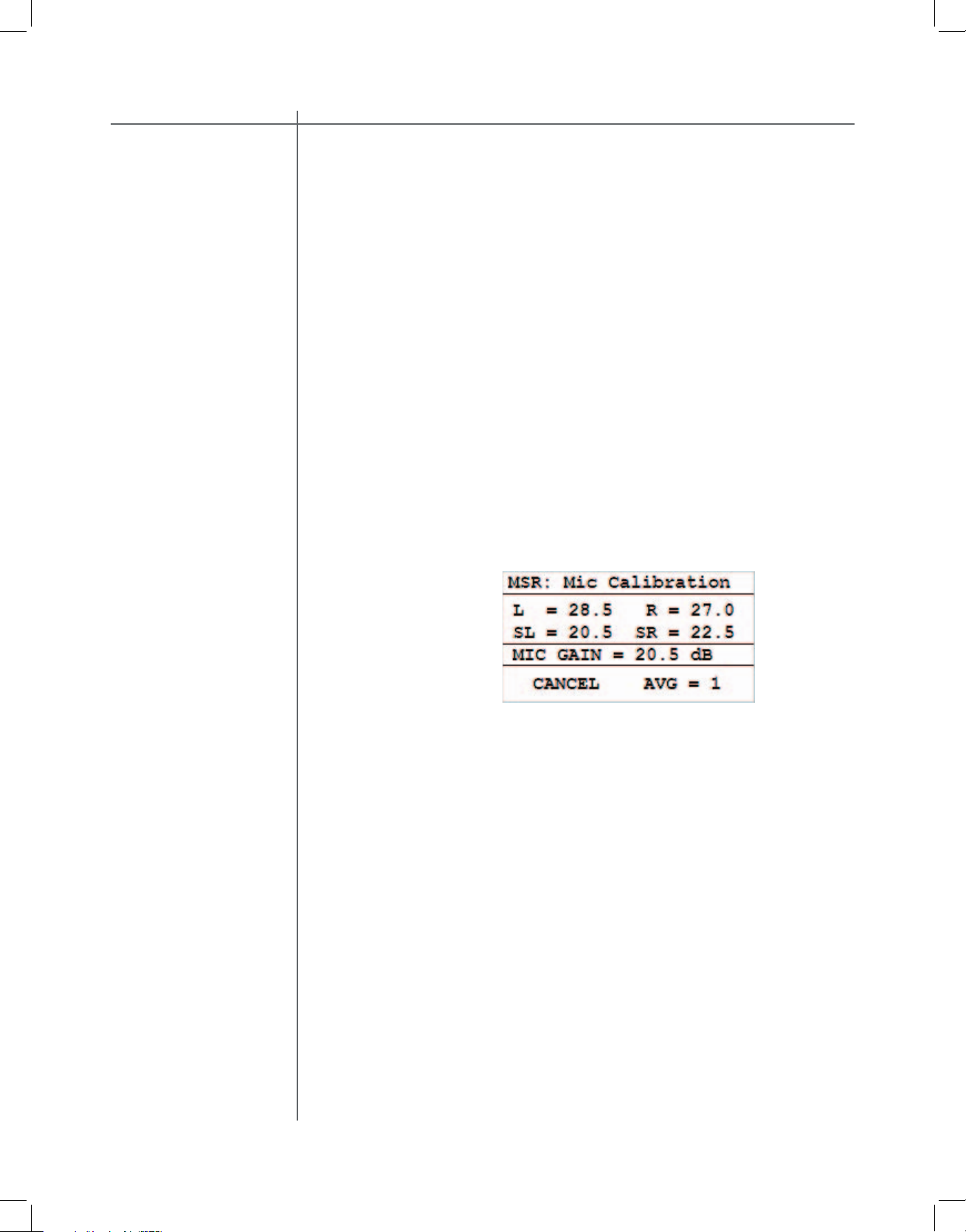
on the START button. The following screen will be displayed:
Fig. 6. Microphone calibration and measurement screen
After the measurements are completed, click on the
EXIT option and then click
on the MENU button to go back to the DRC-RCS screen (Fig. 3). At any time during the measurement process you can click on the CANCEL option to cancel the
process. After the measurement is completed or the measurement was canceled,
the CANCEL option changes its name to EXIT.
Page 16
CAUTIONCAUTION
Tact Audio
4. Enable automatic room correction. In the DRC-RCS screen (Fig. 3), select
correction preset 1. Make sure that crossover fi lters are enabled and proper
crossover frequency is selected. Crossover fi lters can be adjusted at any time
even after you enable the automatic feature. Click on the AUTO-OFF menu option
to enter the Auto Correction screen (Fig. 5). Note that in bypass mode the AUTOOFF(ON) menu option is not displayed.
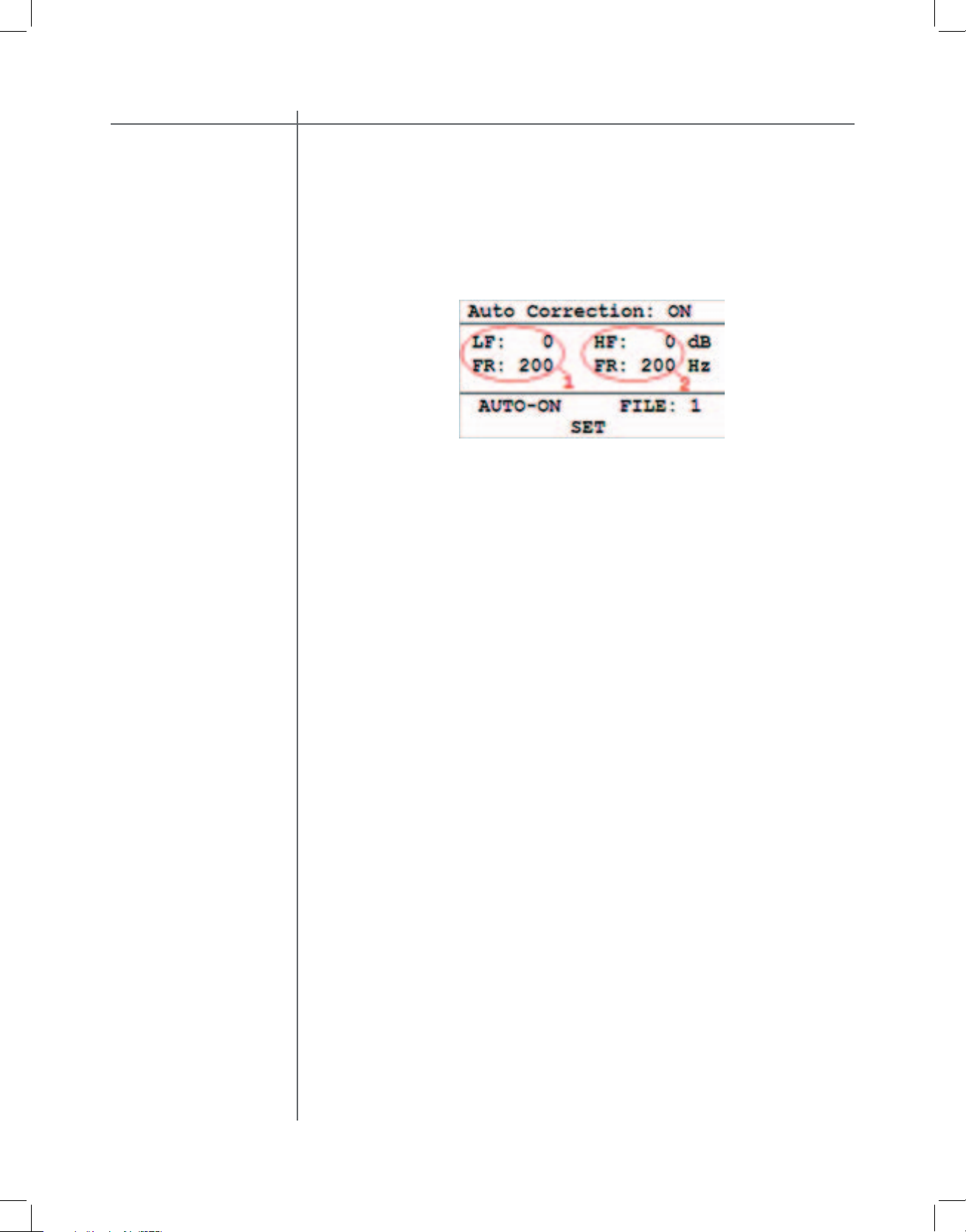
Fig. 5 Auto Correction screen.
In the Auto Correction screen click on the AUTO-OFF menu option to display
AUTO-ON and then click on the SET option to activate automatic room correction. In a split of a second the 2.2 XP will calculate target curves based on LF,
HF, crossover fi lter selection parameters and measurement data as saved in
measurement fi le 1.
You are ready to perform your fi rst listening test. Use LF parameters to add gain
or attenuation at frequencies bellow the frequency as displayed in LF parameter
bloc (1). Use HF parameters to add gain or attenuation to frequencies above the
frequency as displayed in HF parameter block (2). In this way you can shape target curves to match your specifi c listening needs.
Please note that changes you make on this screen do not take effect until you
click on the
SET option.
Page 17
Tact Audio
This operating mode assumes a stereo system consisting of two main channels
and one subwoofer. To select 2.1 mod from the main screen, click on the MENU
button to enter the main menu screen and then select the MODE menu. In the
MODE menu click on the STEREO 2.1 option. This will select 2.1 mode and display it on top of the screen (1).
Fig. 6. Mode menu. 2.1 mode selection is displayed in the upper left corner (1).
The rest of the procedure is the same as in 2.2 mode. Note the change in the
measurement screen in Fig. 7. The Tact-2.2 XP will automatically select channels
for measurements based on the mode selection.
Fig. 6. Mode menu. 2.1 mode selection is displayed in the upper left corner (1).
The rest of the procedure is the same as in 2.2 mode. Note the change in the
measurement screen in Fig. 7. The Tact-2.2 XP will automatically select channels
for measurements based on the mode selection.
Page 18
CAUTIONCAUTION
Tact Audio
This operating mode assumes a stereo system consisting of two main channels
only. To select 2.0 mode from the main screen, click on the MENU button to enter
main menu screen and then select the MODE menu. In the MODE menu click on
STEREO 2.0 option. This will select 2.0 mode and display it on top of the screen
(1).
Fig. 8. Mode menu. 2.0 mode selection is displayed in the upper left corner (1).
The rest of the procedure is the same as in 2.2 mode. Note the change in the
measurement screen in Fig. 9. The Tact-2.2 XP will automatically select channels
for measurements based on the mode selection.
Fig. 9. Measurement screen for 2.0 mode. Note that SR does not have a rectangle
around indicating that this channel is not set for measurement.
In 2.0 mode only the Left and Right channels will be measured. At the end of the
measurement process the Subwoofer Left and Subwoofer Right measurement
data will be set to 0 dB fl at response.
Page 19

Tact Audio
Page 20
CAUTIONCAUTION
Tact Audio
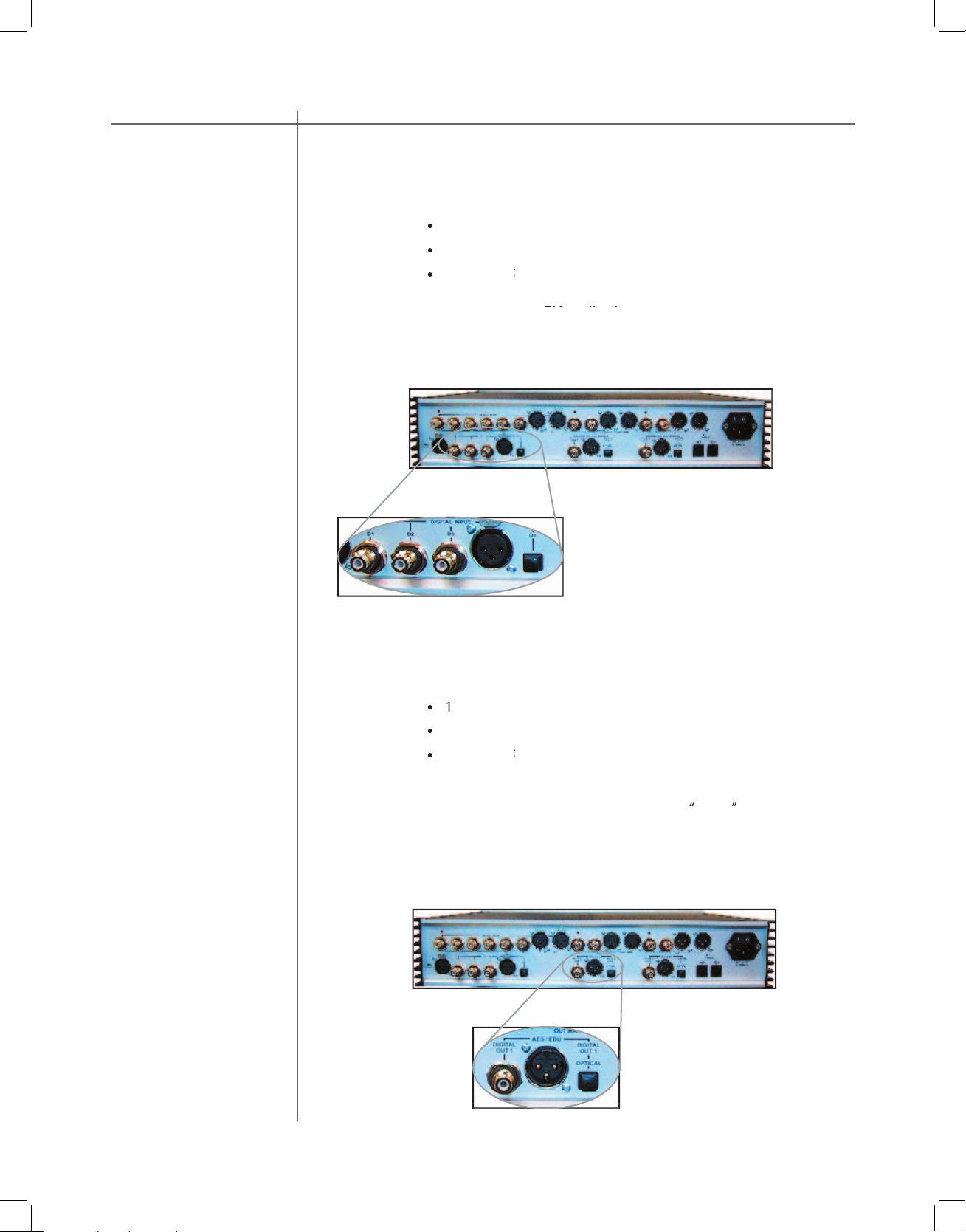
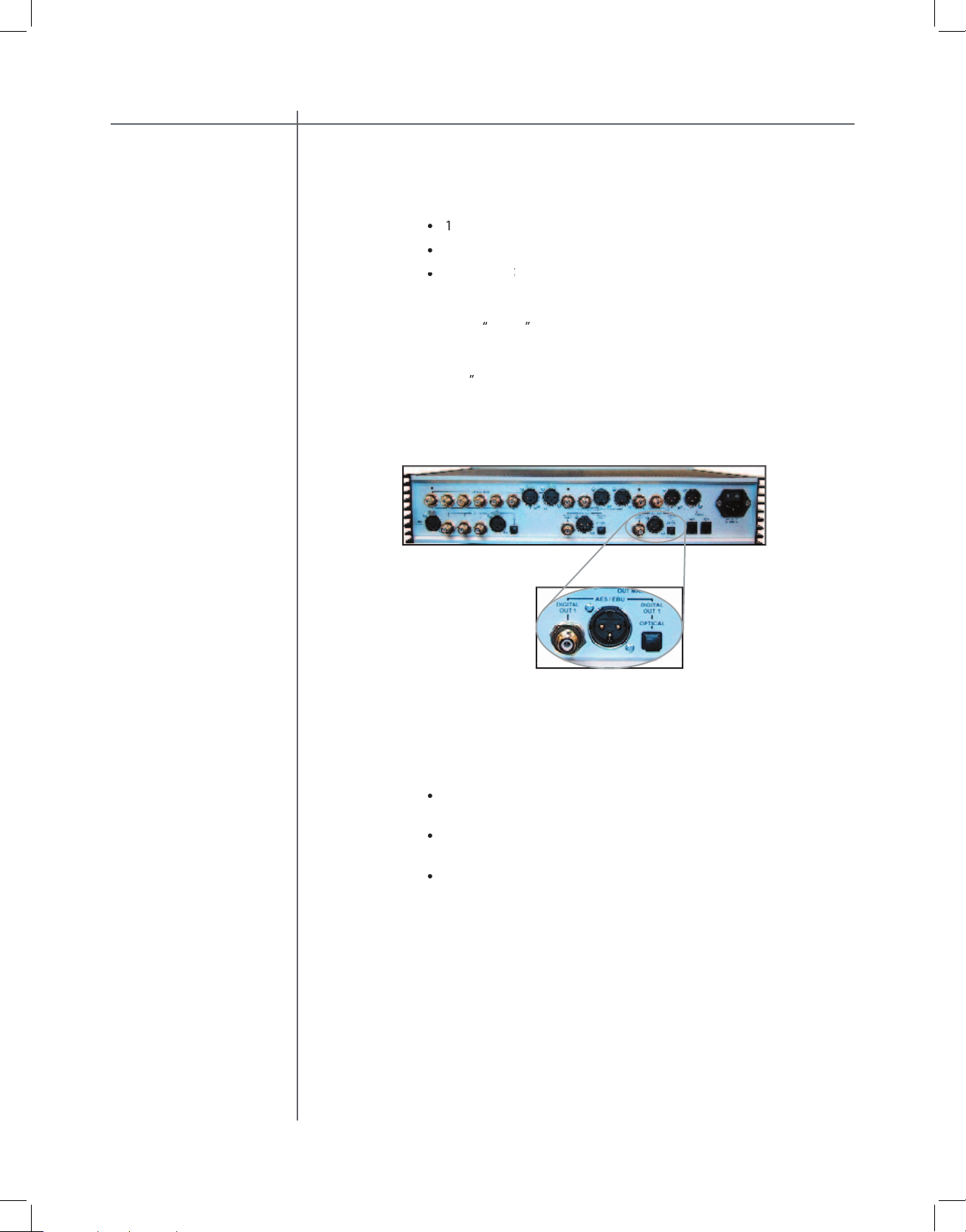
The RCS 2.2 XP has 5 digital inputs:
to 96 kHz /16-24 bits.
main channels
The RCS 2.2 XP has 3 digital outputs for the main channels:
menu.
The main channel output is used for your main speakers or for Mid/High-frequen-
Page 21
Tact Audio
subwoofers
The RCS 2.2XP has three digital outputs for subwoofer(s) :
menu. (TosLink does not support 192kHz)
The sub output is for your subwoofer(s) and can be confi gured for either mono or
“
menu to set the appropriate output mode 2.0, 2.1, or 2.2.
without adding extra cost for features certain users might not use. There are there-
fore 3 optional modules that can be installed:
ADC-converter module for analog inputs such as Tuners,
Page 22
CAUTIONCAUTION
Tact Audio
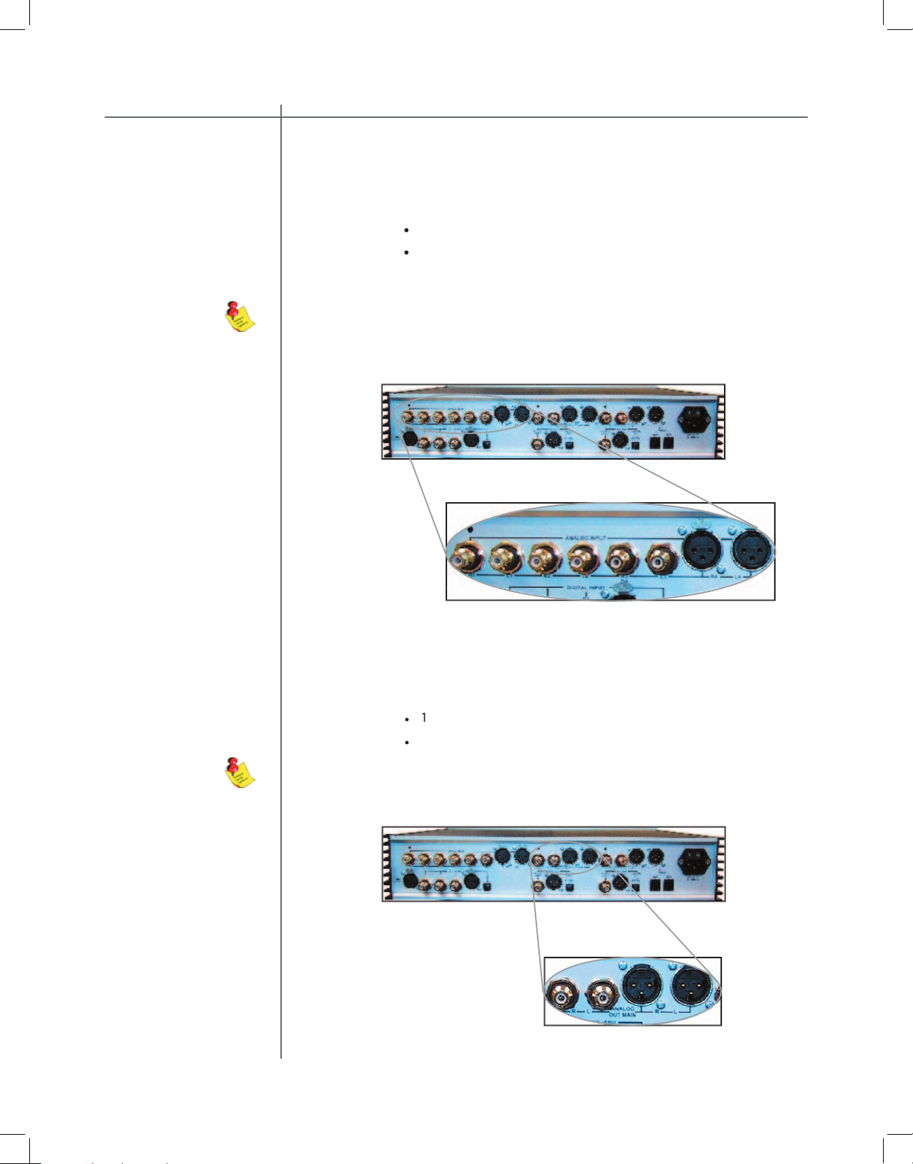
The RCS 2.2 XP has 2 stereo analog outputs for the main channels when the op-
tional DAC-MAIN module is installed:
stereo single ended (RCA)
The RCS 2.2 XP has 4 stereo analog inputs when the optional ADC module is
stereo single ended (RCA)
Page 23

Tact Audio
The RCS 2.2 XP has 2 analog outputs for subwoofer(s) when the optional DAC-
taking a room measurement for dynamic room correction.
Page 24

CAUTIONCAUTION
Tact Audio
The RCS 2.2 XP has two RS232 interface ports:
port for communication with your personal computer.
Page 25
Tact Audio
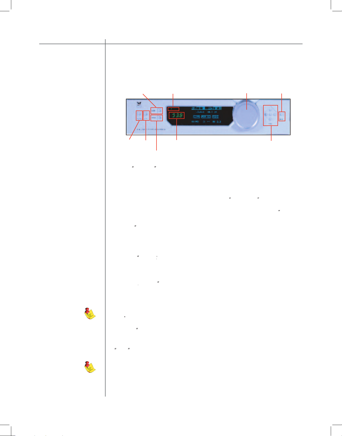
button to toggle between Standby mode and ON.
The display will indicate Standby mode by displaying a small green light in the left
The master volume is controlled by turning the
TacT wheel
while the unit is in Mute mode - the volume level indicator will briefl y indicate the
“
button to select the analog input. This is a toggle switch, and
button .
The front panel controls on the RCS 2.2 XP will allow you to access and control all
The remote and front panel controls are disabled whenever a Personal
Analog Input Selector
Volume Level
Ple ase note that the optional ADC module is required for analog in-
Page 26
CAUTIONCAUTION
Tact Audio
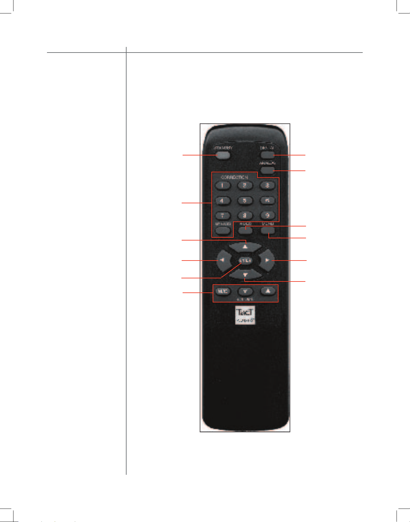
The remote control is used to access the front panel display controls and menus.
4
2
9
1
3
5
6
7
10
8
12
Page 27

Tact Audio
The STANDBY button will either turn the RCS 2.2 XP on or will place it int
The standby button is also used to save changes that were made in the menu
The DIGITAL button will scroll sequentially, allowing for selection of one of the 5
The ANALOG button will scroll sequentially, allowing for selection of one of the 4
4 - CORRECTION block
The CORRECTION block consists of 10 buttons. The buttons are numbered from
The MENU button will switch the front panel display from the status screen to the
menu screen.
The VIDEO button is inactive with this unit.
The UP navigation button is used to select menu options and/or change their
values.
The DOWN navigation button is used to select menu options and/or change their
values.
The LEFT navigation button is used to select menu options and/or change their
values.
The RIGHT navigation button is used to select menu options and/or change their
values.
The ENTER button will select the menu option currently marked by the blinking
The VOLUME block consists of three buttons.
The “
The “
The “
Page 28

CAUTIONCAUTION
Tact Audio
To move the cursor indicator use the front panel or remote control navigation but-
tons. To select an option press the “
Correction preset selection
EQ preset selection
Master level in dB
Correction menu option
Parametric EQ menu option
Output sampling frequency indicator
Input sampling frequency indicator
RCS 2.2 XP operating mode
Master level in dB
Mono mode indicator.
Correction preset selection
To select one of the nine correction presets or to bypass them use the “
LEFT” or
“RIGHT” navigation buttons to position the cursor over CR (1). Once the cursor
is positioned over CR (1) press the “ENTER” button. The system will then display
a pull down list containing all presets. Use the “UP” and “DOWN” navigation buttons to point to the desired correction preset and then press the “ENTER” button.
This action will engage the selected preset and will display the new selection in
the CR box (1). Once the cursor is positioned over CR (1) you can also select a
correction preset by pressing one of the ten buttons located in the block labeled
“CORRECTION” on the remote control. The 2.2 XP will display a <*> next to the
selected presed indicating that the preset was loaded.
EQ preset selection
To select one of sixteen parametric EQ presets or to bypass them use the
“LEFT” or “RIGHT” navigation buttons to position the cursor over EQ (2). Once
the cursor is positioned over EQ (2) press the “ENTER” button. The system will
then display a pull down list containing all presets. Use the “UP” and “DOWN”
navigation buttons to point to the desired EQ preset and then press the “ENTER” button. This action will engage the selected preset and will display the new
selection in the EQ box (2). Once the cursor is positioned over EQ (2) you can
also select a correction preset by pressing one of the ten buttons located in the
block labeled “CORRECTION” on the remote control. The 2.2 XP will display a
The main screen is displayed when the RCS 2.2 XP is powered on.
Note: with the remote control you can only select the fi rst nine presets. To
select the rest you must use front panel controls.
Page 29

Tact Audio
This fi eld displays the system master level in dB. It is calculated as relative gain
minus
99.9 plus GAIN (as set in t
the main parametric EQ menu.
This displays the currently selected output sampling frequency. The output sam-
This displays the sampling frequency of the currently selected digital input. The
This displays the systems operating mode. The operating mode can be modifi ed
from the “MODE” main menu option.
When the MONO
option in the MODE m
the MONO option is set to OFF, this
fi eld is not visib
Note: An EQ preset must be enabled from the main screen for the PAR EQ
menu to be active. If the EQ preset is set to “BP”, the PAR EQ controls are
disabled.
Page 30
CAUTIONCAUTION
Tact Audio
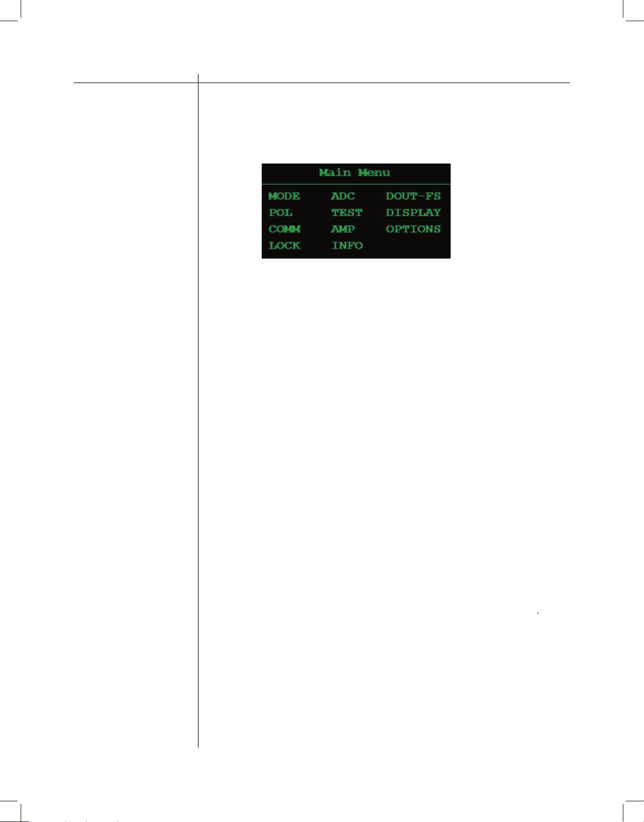
The main menu screen lists all of the RCS 2.2 XP general menus.
To highlight a menu option use the navigational buttons. To enter a highlighted
ADC menu
analog input sensitivity.
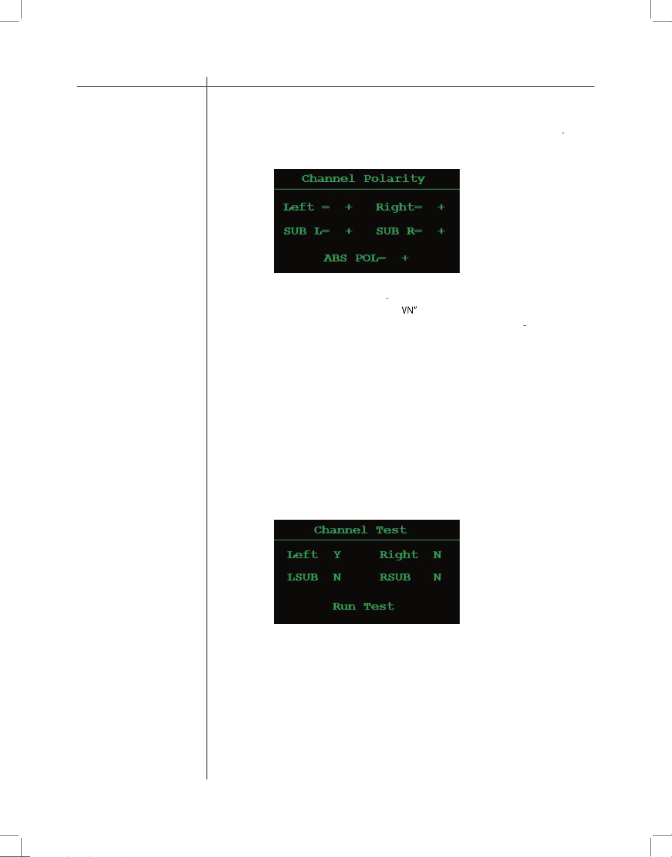
Left/Right and Sub Left/Right digital output
the
channel polarity as well as the absolute
TEST menu
2.2 XP device address.
through the First Scre
Page 31
Tact Audio
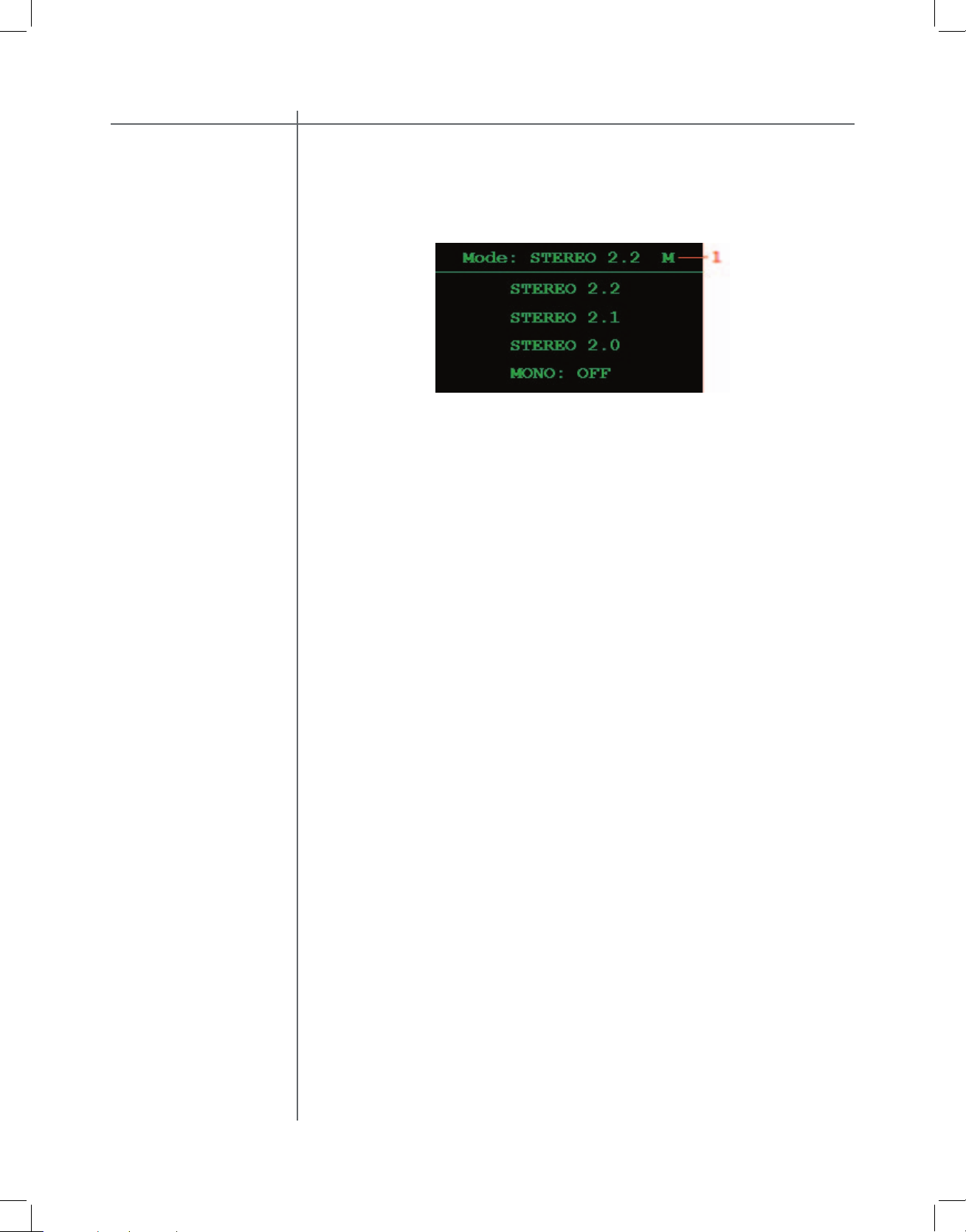
Use this menu to set the RCS 2.2 XP to one of four operating modes.
To
highlight an option use the navigational buttons. To enter a highlighted option
STEREO 2.2 This mode produces 4 output signals. Left, Right, Left
SUB, and Right SUB
STEREO 2.1 This mode produces 3 output signals. Left, Right and one
SUB signal. In this mode the SUB signal is mono and is
output to both the Left SUB and Right SUB outputs.
STEREO 2.0
This mode produces 2 output signals. This is standard
two channel stereo mode. In this mode there is no signal
at the subwoofer outputs.
This option can be set to ON or OFF. When set to ON
the system will output the same signal for both the Left
and Right channels.
Page 32
CAUTIONCAUTION
Tact Audio
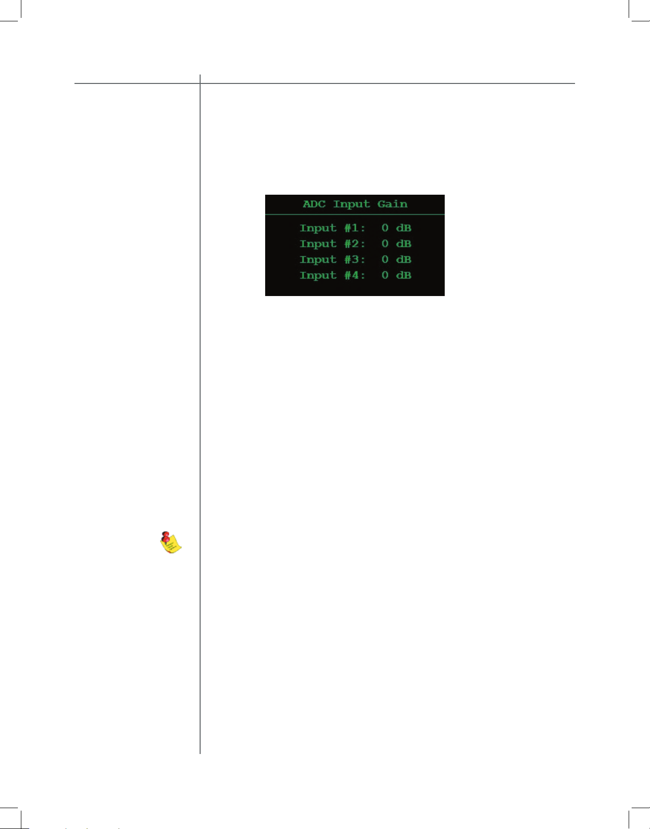
ADC menu
The RCS 2.2 XP can be equipped with a state of the art Analog to Digital Con-
verter (ADC module optional) . To further enhance the converter’s performance,
the system off ers two selectable gain values for the ADC input stage, 0dB or -6dB.
These values can be assigned to each input independently.
To select an option use the “
tions.
the maximum input voltage for that particular input will be 4.4 Vrms.
Vrms.
This menu option has no eff ect on the digital inputs.
Page 33
Tact Audio
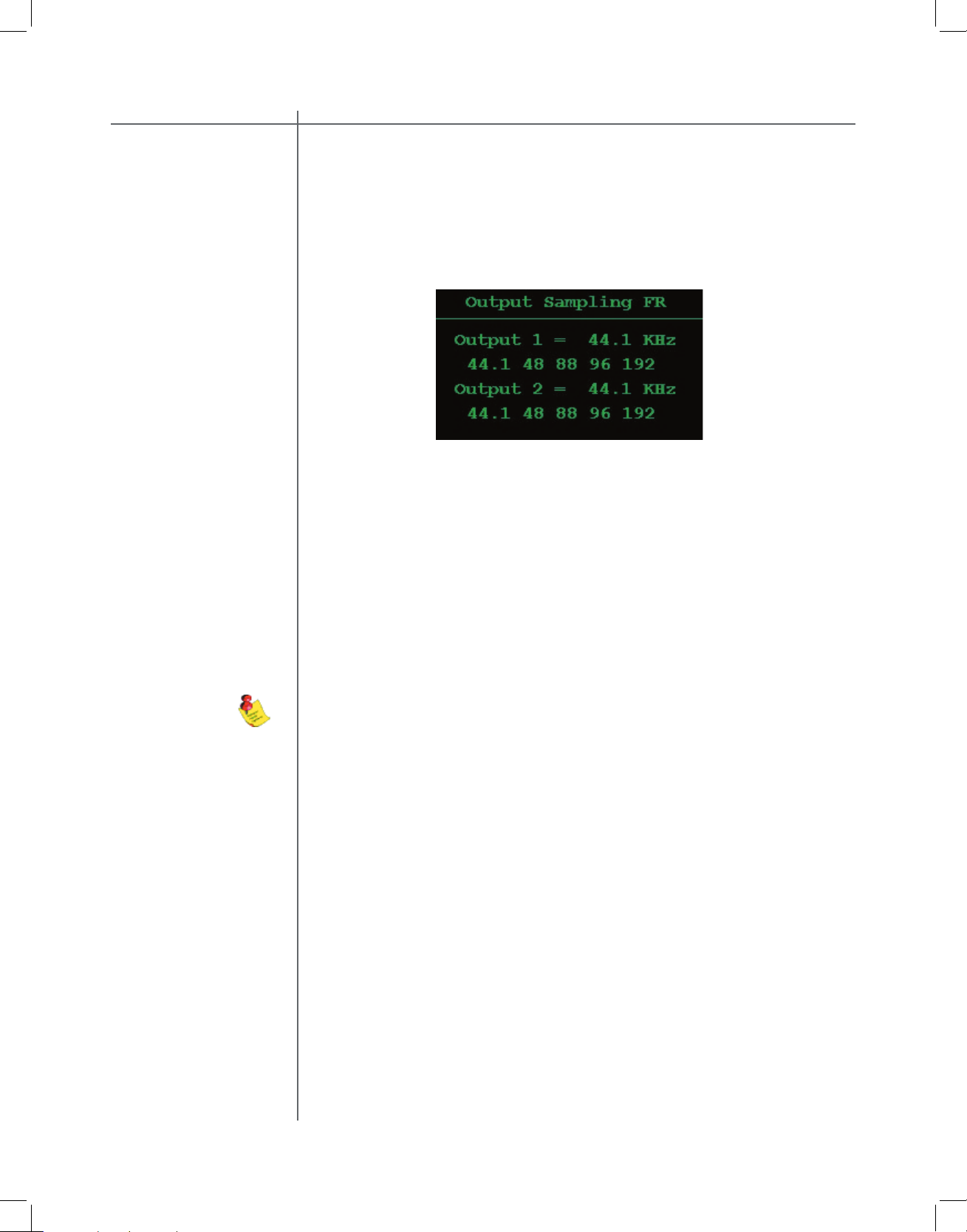
The RCS 2.2 XP is equipped with a sample rate converter on each digital output. Each output can independently be set to 44.1, 48, 88, 96 and 192 KHz sampling frequencies.
To set the sampling frequency for digital outputs 1 or 2, use the “LEFT” or
“RIGHT”
buttons to highlight the desired option (44.1, 48, 88, 96,
192 kHz) and then press the “ENTER” button to make the selection.
Output 1 refers to the Left/Right channel output
.
Output 2 refers to the Sub Left/Right channel output.
The RCS 2.2 XP is equipped with separate sample rate converters at each Left/
Right and Sub Left/Right o
utput. The Left/Right and Sub Left/Right outputs can
be programmed to have diff erent sampling frequencies.
This menu does not aff ect the analog output sampling frequency
and has no eff ect on the analog outputs.
Page 34
CAUTIONCAUTION
Tact Audio
The test menu is designed to allow for a quick system check. When engaged it
will produce pink noise on all selected channels. When a channel is set to “
Y
TEST menu
Tttt
To select an option use the “
To highlight an option use the the “
then press the “
Page 35
Tact Audio
The display menu allows for control over the front panel display appearance.
To select an option use the “
the “
1. Timeout This option is used to turn the front panel timer “ON” or
“OFF”. When this option is “ON” the front panel timer will
Timeout in
option, and then turn the display OFF or dim it to a
option.
2. Timeout in sec This option is used to set the number of seconds that the
display will remain on before turning off or dimming after
accessing an option on the front panel display. This parameter can be set to a value from 3 to 30 seconds. For
example, if it is set to 15 seconds the front panel timer
will count to 15 seconds and will then turn the display
OFF or dim it to a level specifi ed by the OFF Brightness
option.
3. ON Brightness This option determines the front panel brightness after
the unit is powered on or an option on the front panel display is accessed. This parameter can be set to any value
between 1 and MAX(16).
4.
This option determines the front panel brightness after
timeout has expired. This parameter can be set to any
value between OFF (0) and MAX(16).
Page 36

CAUTIONCAUTION
Tact Audio
This menu has only one option,
To change the system device address highlight the “
Page 37

Tact Audio
The AMP menu is designed to allow the RCS 2.2 XP to interface with the TacT
This setting should be ENABLED only if you have a Tact digital amplifi er
AMP menu
the amplifi er’s front panel and IR controls are disabled. Use the RS232 port
Tact amplifi ers connected to the RCS 2.2 XP. When the AMP option set to
Tact amplifi ers connected to your system you will not be able to control
the output level from the RCS 2.2 XP volume control. The output is sent at
To change the settings use the “
option is
set to DISA
mater level control will aff ect both the digital and the ana
option is
set to
the Left/Right analot or digital output signal. The Left and Right channel signal
will output the maximum signal level, which is equivalent to the 99.9 setting on
the volume display. The front panel master level information (relative read out,
The same applys to
th
option.
Tact digital amplifi er is connected only one option should be set to
the output that uses Tact digital amplifi ers.
Page 38
CAUTIONCAUTION
Tact Audio
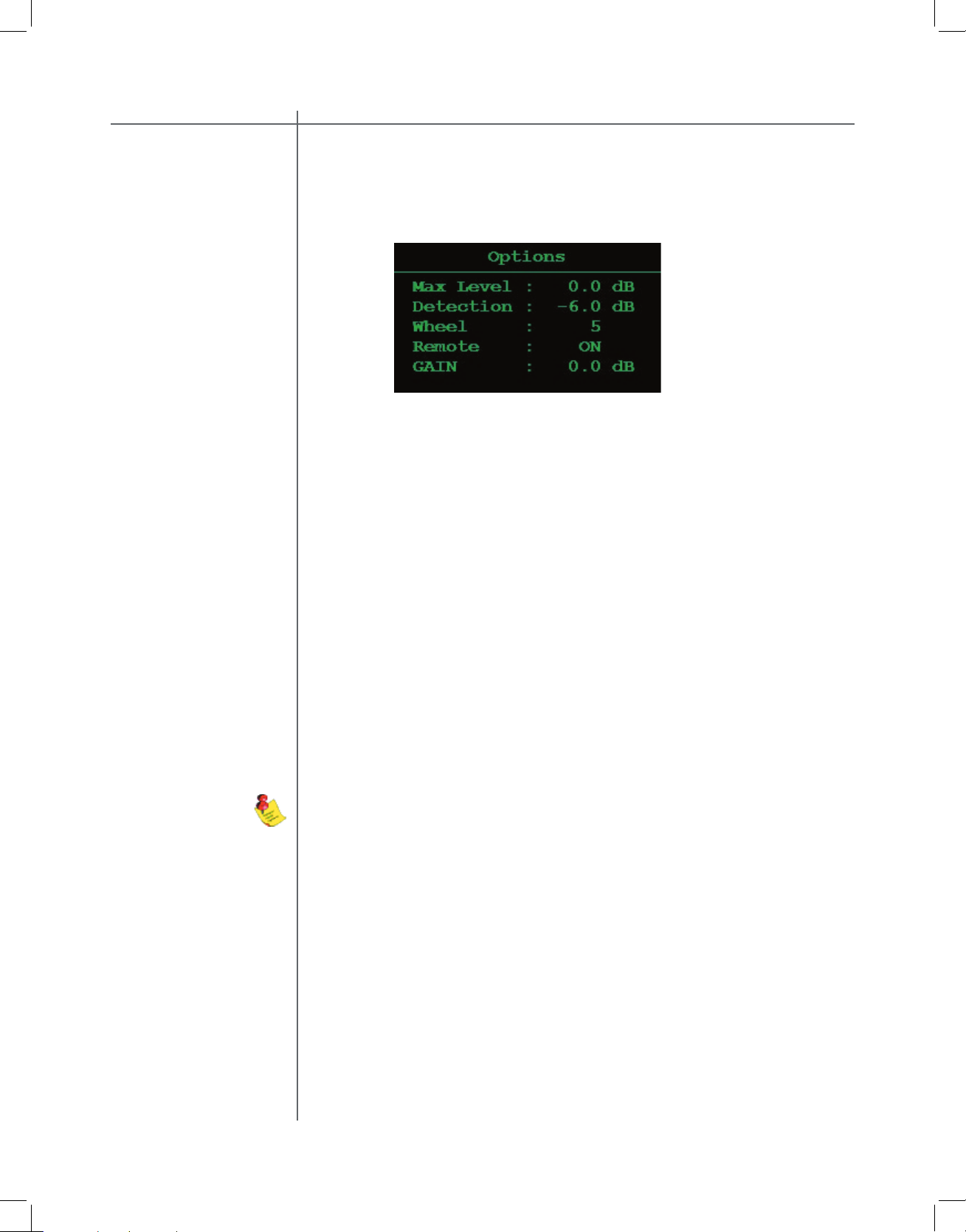
The options menu allows for control of the systems maximum signal level, signal
To select an option highlight it using the “
To modify a selected option use the “
Max Level
This option controls the system’s maximum signal level.
Detection
This option sets the signal detection threshold. If the
To use it as a signal presence indicator set the
to a value close to -90.0 dB. To use it as near clip indica-
tor set the
to a value close to 0.0 dB. This pa-
When the para
front panel turns on
, it is only an indication that
the input audio signal
Wheel
This option sets the wheel sensitivity. The wheel sensitiv-
the Wheel for volume control. The lower the setting the
the faster the volume increases with each turn of the
Wheel.
This option enables and disables the remote control.
Page 39
Tact Audio
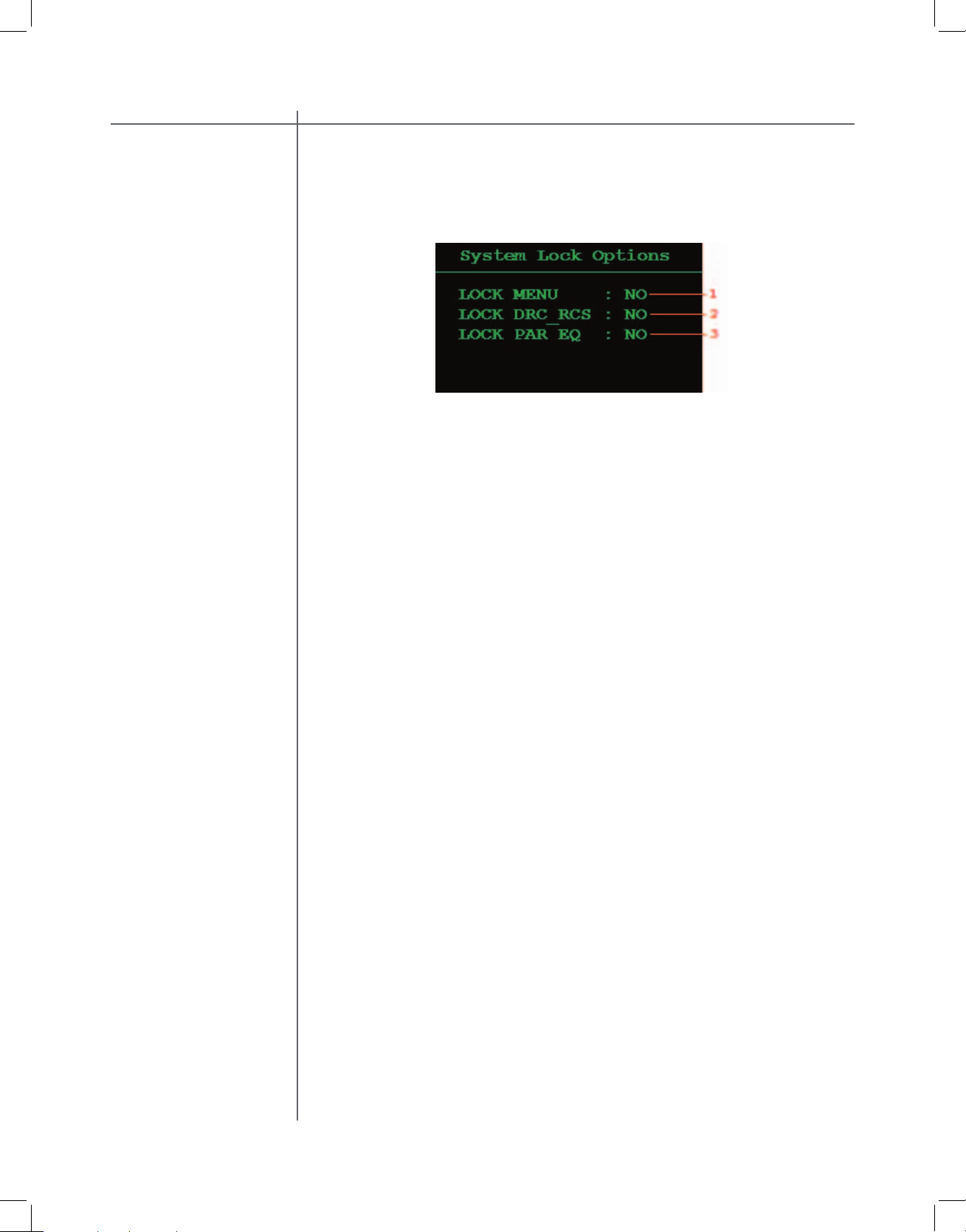
menu
To select an option highlight it using the “
To modify a selected option use the “
1. LOCK MENU
When this option is set to YES all Main Menu options ex-
2. LOCK DRC-RCS
When this option is set to YES the user can not change
3. LOCK PAR EQ
When this option is set to YES the user can not change
Page 40
CAUTIONCAUTION
40
Tact Audio
ware that is i
T
INFO menu
Page 41

41
Tact Audio
fi rst screen.
menu
To highlight a menu option use the navigational buttons. To enter a highlighted
Use to set individual channel level.
menu
menu
This option allows for correction preset selection. Place
the screen cursor over this option and use the UP DOWN
to turn dynamic room correctin ON and
option
This indicates the status of the corssover package. The menu
Page 42

CAUTIONCAUTION
42
Tact Audio
to se
t
menu
then use the LEFT and RIGHT buttons to adjust individual channel level set-
tings.
the master level control, and system GAIN as set in OPTIONS menu.
menu
to se
t
settings.
then use the LEFT and RIGHT buttons to adjust individual channel level set-
tings.
fi le. These values can be manually changed but once the correction preset is
To use manually set delay times set the fi eld (1). Tact-2.2 XP keeps track of de-
Page 43
43
Tact Audio
w the s
ymbolic names ass
To highlight a menu option use the navigational buttons. To select a highlighted
Use this option to set low-pass fi lter order. This option can be set from 1
to 24.
from 1 to 12
4.
the
Displays the currect correction preset.
Page 44

CAUTIONCAUTION
44
Tact Audio
to
perform room response measurments
without a
menu
MSR MIC CAL. When this option is set to ON, the room correction algorithm will
apply the microphone calibration fi le to the measurement data. When this option
is set to OFF, the microphone calibration fi le is ignored.
MIC FILE. This fi eld displays the microphone fi le name used to perform microphone calibration. The microphone calibration fi le data is saved in 2.2 XP internal
memory. For more details on how to transfer microphone calibrations fi le to 2.2 XP
memory, please refer to the Microphone section of the PC software manual.
AVG This is a very important measurement parameter. It equals the number of
measurements that are averaged prior to being saved. The averaging process
reduces the effects of random environmental noise. Typical Average values go
from 10 to 30.
DELAY. If you do not want to be in the room while measurement is in progress,
set this parameter to a few seconds to allow you to exit the room. For example, if
DELAY = 10 the system will wait for 10 seconds before it starts pulsing.
PULSE. This parameter sets the relative level of the output measurement pulse.
Minimum level is 1% and maximum level is 100%.
FILE. Use this option to assign a File number to the measurement you are just
about to perform. At the end of the measurement process, the measurement data
for all four channels will be saved in the selected File number. Tact-2.2 XP supports up to seven measurement fi les. In another words you can save up to seven
different measurements in 2.2 XP internal memory.
Use L, R, SL and SR options to select (enable) a channel for measurement.
Channels are labeled as L for left, R for right, SL for subwoofer left and SR for
subwoofer right channel. Selected (enabled) channels are marked by a rectangle.
To select or deselect a channel place the cursor over desired channel and press
ENTER button.
Page 45

45
Tact Audio
In most cases, factory presets are optimum and users can proceed directly with
peforming actual measurements. To initiate the room measurement process, click
on the START button. The microhpone calibration and measurement screen will
be displayed:
After the measurements are completed, click on the EXIT option and then click
on the MENU button to go back to the DRC-RCS screen (Fig. 3). At any time during the measurement process you can click on the CANCEL option to cancel the
process. After the measurement is completed or the measurement was canceled,
the CANCEL option changes its name to EXIT.
For instructions on how to
to p.12.
Page 46

CAUTIONCAUTION
46
Tact Audio
This menu is used to control the 12 band parametric equalized. This menu is ac-
Page 47

47
Tact Audio
When a Par Eq preset other that BP is selected this screen can have two forms:
When the LINK option is set to NO the
following screen is displayed.
When the LINK option is set to YES the fol-
To highlight a menu option use the navigational buttons. To select a highlighted
for both the left and right channels. To change the LINK setting highlight
the current LINK selection and press ENTER button to toggle between
the YES and NO selections.
through the available presets. When the desired preset is displayed press
the ENTER button to select it.
4.
To change the LOCK setting highlight the current LOCK selection and
Page 48

CAUTIONCAUTION
48
Tact Audio
This is an example of the linked parametric EQ fi lter table. Its display allows for
To change a parameter fi rst highlight it and press ENTER button. Then use the
Page 49

49
Tact Audio
The following is an example of an un-linked ParEQ table featuring the left chan-
To change a parameter fi rst highlight it and press ENTER button. Then use the
Page 50

TacT Audio, Inc.
201 Gates Road Unit G, Little Ferry – New Jersey 07643, USA
Phone: +1 201 440 9300 – Fax: +1 201 440 5580 – Email: info@tactaudio.com
www.tactlab.com
 Loading...