

Tact Audio BOZ 216 2200 Owner Manual
Owner’s Manual
boz
2 1 6 / 2 2 0 0
2 1 6 / 2 2 0 0
boz


welcome
Thank you for choosing what we believe is the world’s finest and most advanced digital amplifier. Every BOZ
unit has been engineered to be an uncompromising listener’s tool, designed to satisfy the most demanding
enthusiast. You’ll find that we devote considerable attention to satisfying your specific needs, no matter what
your listening preferences may be.
3
The BOZ 216/2200 redefines amplification. The digital input is taken to the central processor where it is
reformatted into a pulse width modulated signal of extreme precision. The pulse rate is measured at precisely
384,000 pulses per second. Each pulse can have 256 different widths, with the narrowest pulse being a mere
100 millionths of a second wide. The clock frequency therefore is 98 MHz. The central processor computes
exactly the right combination of pulse widths to produce an incredibly accurate waveform.
Once the decision of the duration of the pulse is made, the central processor controls FET-switches at the out
put with extreme precision. Voltage and current are drawn from the power supply and are fed to the speakers.
The level of playback is controlled by adjusting the voltage of the power supply. As this voltage is switched di
rectly to the speakers, it is of paramount importance that the power supply be totally free of ripple and noise.
For BOZ digital amplifiers, a switch mode power supply of extreme precision with ripple rejection of more
than 135 dB has been developed. At full volume the BOZ 216/2200 delivers 200 Watts into 8 ohms. To reduce
the volume the voltage of the power supply is reduced. This means that the volume control is no longer part
of an active circuit.
Exclusive technology
The most fundamental departure from conventional amplifiers is that the BOZ 216/2200 defines the waveform mathematically - it does not try to follow or emulate a waveform by using feedback or feed-forward.
So why hasn’t anybody thought of this before? Why has this not been done before? Well, try to switch more
than 60 volts DC 384,000 times per second without creating even a whisper of noise at a distance of 1” from
the tweeter! Only in the past few years has it been possible to create a fully digital “amplifier”.
boz introductionboz introduction
-
-
Key Features
Ultra high precision DA conversion
Upsampling to 384,000 Hz before conversion
Full resolution at -30 dB
Software upgradable DSP section
DSP-based floating point electronic crossovers
Digital pre-amplification with 24-bit resolution at a playback level of -30 dB!
Output of 2x200W into 8 Ohm, or output of 2x400W into 4 Ohm load, with extreme load tolerance
NO feedback or feed-forward locally or globally is utilized in the signal path.

4
boz
216/2200
boz line introduction
The Tact Millennium
Tact Audio introduced the Tact Millennium, the world’s first true digital amplifier, back in 1998. It
was not only heralded as the most important technological breakthrough in decades, it was also
immediately recognized as the greatest sonic improvement in amplification ever.
The audio press was unanimous in its praise: “Without any true competition,” “It sounded much
more like live music than anything else I had heard,” and “Overwhelming transparency,” were
among the words of praise.
The M2150 & S2150
In 2002 Tact Audio introduced the second series of digital amplifiers, the M/S-2150. Until the arrival
of the M/S-2150 series, no other digital amplifier came anywhere near the performance level of the
Tact Millennium.
The M/S-2150 series amplifiers were designed in a more efficient way than the Millennium. They
also feature major improvements in the digital signal processing section. Continuous research
and development as well as advancements in technology have allowed us to reduce prices while
maintaining quality. The significant improvements in the layout and digital design ensured that
the 2150 reached a new level of excellence and became the world’s best selling true digital power
amplifier.
The Boz Line
With the 2005 introduction of the BOZ line of digital amplifiers, Tact Audio offers the world’s first
multi-channel digital amplifier with performance exceeding that of its predecessors, the Tact Millennium and Tact M/S-2150. The first product of the BOZ line is the BOZ 216/2200 true 16-channel
digital amplifier.
The BOZ design is based on a separate power entry and control module, the BOZ-216 (referred to
as the BOZ-216 control unit), combined with two channel power amplifier modules, the BOZ-2200
(refereed to as amplifier modules). The BOZ-216 control unit can handle up to 8 BOZ-2200 modules
for a total of 16 channels of amplification.
The Tact Millennium
was awarded the
prestigious
iF Design Award in
2001
www.ifdesign.de
The TacT M2150 was
awarded the Stereotimes Most Wanted
Component Award
for three consecutive
years: 2003, 2004, and
2005.
www.stereotimes.com
The BOZ 216/2200
was awarded the Stereotimes Most Wanted
Component Award for
2005 - a mere month
after its initial release.
www.stereotimes.com
The input AC power connects to the BOZ-216 control unit via two power entry modules. The
power entry modules each have built in line filtering. Each power entry module can handle up to
1250 W of power. Both power entry modules combined together can deliver 2500 W of power. In
this way twelve amplifier channels can simultaneously deliver 200 W of power.
While preserving the core design philosophy of the Tact Millennium and the Tact M/S-2150, the
new BOZ 216/2200 amplifier is designed with the latest in digital signal processing technology.
Special attention has been paid to board design and signal distribution between the modules
inside the BOZ-2200. All digital audio signal routing is implemented with differential LVDS logic
design. In order to further reduce system jitter the previously existing phase locked loops (as in the
Millennium and M/S-2150) are completely eliminated.

characteristics of the ‘boz’ line
Mono Block Design
Each amplification channel in the BOZ-2200 is self contained with a separate processor-controlled
power supply and a PWM circuit.
Floating Point Processing
High precision floating point processing. All real time audio signal processing algorithms are implemented with floating point arithmetic.
LVDS (Low Voltage Differential Signaling)
All digital audio signals in the BOZ-2200 are routed with LVDS (low-voltage differential signaling)
drivers/receivers. This design ensures maximum signal integrity for all digital audio signals.
External Clock
Each BOZ-2200 can accept an external clock for jitter-less reception of AES/EBU and SPDIF signals.
5
boz introductionboz introduction
Crossover Package
The crossover package running on the BOZ-216 control unit does not require computer support to
implement Butterworth and Butterworth squared filters. The crossover package supports:
1. Low-pass filters
2. High-pass filters
3. Band-pass filters
The above are supported with a filter cutoff frequency anywhere between 15 Hz and 24000 Hz
with filter slopes from 1-st to 12-th order.
Parametric Equalization package
The parametric equalizer package features 12-band parametric equalization per channel and ten
presets per channel. The ParEq specs are:
1. Filter center frequency between 15Hz and 24000Hz
2. Filter level adjustment from -18.0 dB to +12 dB in increments of 0.1 dB
3. Filter bandwidth from 0.01 to 2.5 octaves
Room Correction Package
The room correction package running on the BOZ-216 control unit is assessable directly from the
front panel. Front panel access lets you choose between 10 preset correction settings. The correction settings are loaded to the unit via the provided RS232 cable. The room correction technology
utilized in the BOZ line is derived from the award winning room correction technology of the
original Tact Audio RCS product line.
Multi Zone Support
Multi zone support - we call them groups. There are in total 9 groups. Eight groups are user configurable and the ninth group has all amplifiers assigned to it automatically. Each group can consist
of any combination of the eight amplifiers. Master volume control will control the volume of the
selected group only. If ALL is selected, then the volume control will affect amplifiers modules in
each group.

6
boz
216/2200
unique technology
The Boz 216/2200 is not Really an Amplifier
The BOZ 216/2200 is not an amplifier at all. No signal amplification takes place whatsoever!
The BOZ-2200 modules are an ultra high precision D/A converters operating in PWM mode with a
master clock set at a speed 2,222 times higher than the CD format, 1,024 times higher than DVDAudio and 35 times higher than the SACD format. In contrast to conventional D/A converters, it
operates at a switching voltage of more than 60 Volts, delivering the equivalent of 400 Watts per
channel in 4 Ohms. All internal signal processing is performed at 96Kz
Conventional Amplification vs. Boz Amplification
The entire active analog signal path consists of a single coil and a single capacitor, forming a 12 dB
per octave low-pass filter at 70 kHz. The voltage of the power supply determines the output level,
thus eliminating the need for any passive volume control.
Compared to a normal amplification chain this is a massive reduction in complexity. In a normal
chain, the output of the D/A converter is sent to an analog buffer stage, then to an analog pre
amplifier with relays, input stage, volume stage and output stage. It is then sent as a low-voltage
analog signal to the power amplifier with an input stage, output stage and feedback loop. Finally,
the signal is sent to the speakers.
-
In a conventional amplifier, all of this complex and costly circuitry requires hundreds of compo
nents. The BOZ 216/2200 digital amplifier replaces all this with just two components.
Added Benefits of the Boz System
In addition to the revolutionary amplifier design, the BOZ Series is equipped with the latest 192
kHz sample rate conversion technology at the digital inputs. All digital audio signal routing is performed by using LVDS logic for maximum signal integrity. All audio signal processing algorithms
are implemented with floating point precision.
Your BOZ-216 control unit achieves total separation of the input AC power from the sensitive and
extremely clean digital audio signals in the BOZ-2200 modules. Inherent to this setup is unparal
leled system-wide noise reduction and maximum signal purity.
-
-

technological advantages
High Resolution at Normal Listening Levels
High resolution at normal listening levels: With a normal amplification chain, resolution is dependent on the volume setting. The power amp is always on maximum level - even when listening at
low levels. In most cases, only the highest level of playback will give full resolution.
In the Boz amps, the playback level is controlled by the voltage of the power supply. At low levels,
the supply is at low voltage but the signal remains identical. Starting at a level of 30 dB below
maximum, DSP-controlled digital attenuation takes over. This is done with extreme precision using
floating point arithmetic.
No Feedback
Feedback in normal amplifiers is known to cause ringing in the time domain. The BOZ-2200 approach uses no feedback or feed-forward in the signal path.
Immunity to Loudspeaker back-EMF
Total immunity to loudspeaker back-EMF: Any loudspeaker driven by an amplifier will send current
back into the amplifier. This can make the amplifier behave in mysterious ways as it interacts with
the feedback loops. But with the BOZ digital amplifier, zero feedback and steady-state voltage from
the power supply means that back-EMF can have absolutely no effect on the sound.
7
boz introductionboz introduction
Inherently Free From Ringing
Music is all transients, very few instruments produce anything that resembles pure sine waves.
Conventional amplifiers will overshoot and undershoot transients to varying degrees – simply
because transients are voltage swings. In the BOZ digital amplifier, the signal is determined by the
timing of the switching, while the voltage remains constant. Time cannot resonate and when voltage remains constant, there is no risk at all that the design will produce any ringing.
Low Heat
BOZ digital amplifiers produce far less heat per W/cubic inch than conventional amplifiers. This will
extend the product’s lifetime considerably. The elimination of a mechanical volume control and
relays adds further to the lifetime of the product and ensures that no sonic degradation will take
place over time.
Lowest Ever Power Supply Noise Floor
The power supply has been designed with triple-stage supply noise suppression. The noise floor is
at -135 dB. This is far below the level for any known power conditioning equipment in the industry.
Modular Design
The BOZ system is the epitome of modular efficiency: you decide how many channels of amplification you need and you specify your system accordingly. Optional system features, such as the
Crossover, Room Correction, and Parametric Equalization packages, are also designed with flexibility in mind. All software can be easily added to your system at any time. Modular DSP design also
allows us to provide you with firmware upgrades that you can easily download and install.

8
boz
216/2200
general index
Introduction
TacT Welcome
Boz Line Introduction
Characteristics of the Boz Line
Unique Technology
Technological Advantages
Registration
Contact Information
Resources
Acknowledgments
Getting Started
Safety Precautions
Important Safety Instructions
Cleaning and Maintenance
Unpacking the Boz 216/2200
Accessories
Operating Voltage
Boz - 216 Front Panel
Boz - 216 Back Panel
Boz - 2200 Front Panel
Boz - 2200 Back Panel
Connecting the BOZ-2200 to the Boz-216
Remote Control
Functionality
Specifications
Diagram
3
4
5
6
7
10
10
10
10
12
13
13
14
14
14
15
16
17
18
19
20
20
21
22
System Configurations
Speaker Configurations
Normal Operation
Daisy Chaining & Signal Flow
Horizontal Bi-Amplification
Vertical Bi-Amplification
InOut Menu
InOut Menu
24
24
25
26
27
28
29

Boz Navigation System
9
Accessing Your Boz System
Navigating The Menus
Using the Optical Control Knob
Hierarchical Menu System
GROUP Option
MENU Option
The Ping Command
Individual Menu Screens
The First Screen
AMPS menu
AMP menu
DELAY menu
LEVEL menu
POLARITY menu
InOut menu
OPTIONS menu
MODE menu
CROSSOVER menu
EDIT BUTT & EDIT BUTT SQ menu
ParEq menu
ParEq Left & Right Channel Table menu
RCS menu
SELECT GROUP menu
EDIT GROUP menu
MAIN menu
OPTIONS menu
DISPLAY menu
COMMUNICATION menu
LOCK menu
VERSIONS menu
TIME menu
LIC1 menu
LIC2 menu
LIC3 menu
The First Screen
AMPS Option
32
33
33
33
34
34
35
36
37
40
41
42
43
44
45
46
48
49
50
51
53
54
55
56
57
58
59
60
61
62
63
64
65
66
67
boz introductionboz introductionboz introduction

10
boz
216/2200
registration
Please record your serial number here for future reference. You will need this for
future upgrades and in the event that you should require any service on your
BOZ 216/2200.
BOZ-216 serial number:
BOZ-2200 serial number:
contact information
Technical support is available via phone or e-mail.
Phone:
+01-201-440-9300
E-mail:
info@tactaudio.com
Tact Audio Inc.
201 Gates Road, Unit G
Little Ferry, NJ 07643
USA
resources
www.tactlab.com
www.bozaudio.com
www.roomcorrection.com
acknowledgments
© 2005 Tact Audio Corporation. All rights reserved.
No part of this document may be reproduced or transmitted in any form or by any means, electronic, mechanical, photocopying or otherwise, without the prior written consent of the Tact Audio
Corporation.
The information in this document is subject to change without notice.

getting started
safety precautions
safety instructions & maintenance
unpacking the boz 216/2200
boz-216 front panel
boz-216 back panel
boz-2200 front panel
3
boz-2200 back panel
connecting boz-2200 to boz-216
the remote control
12
boz
216/2200
safety precautions
WARNING
To reduce the risk of fire or electric shock, do not expose this appliance to rain or moisture.
CAUTION
RISK OF ELECTRIC
SHOCK DO NOT OPEN
CAUTION: TO REDUCE THE RISK OF ELECTRICAL SHOCK,
DO NOT REMOVE COVER. NO USER-SERVICEABLE PARTS
INSIDE. REFER SERVICING TO QUALIFIED PERSONNEL.
Should you experience
any mechanical problems, please contact
your dealer or contact
us directly. Aside from
being potentially
dangerous, opening
the unit will void your
warranty.
Tact Audio Support
phone:
+01-201-440-9300
E-mail:
info@tactaudio.com
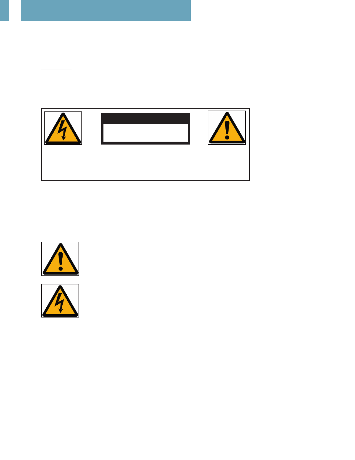
The exclamation point within an equilateral triangle is intended to alert the user
to the presence of important operating and maintenance (servicing) instructions
in the literature accompanying the product.
The lightning with arrowhead symbol within an equilateral triangle is intended
to alert the user to the presence of “Dangerous Voltage” within the product’s
enclosure that maybe of sufficient magnitude to constitute a risk of electrical
shock to a person.

important safety instructions
1.
Read these instructions entirely before installing or operating this equipment.
2.
Keep these instructions.
3.
Heed all warnings.
4.
Do not use this equipment near water or allow it to become wet.
5.
Do not block any ventilation openings. Install in accordance with the manufacturer’s instru-
ctions.
6.
Do not install near any heat sources such as radiators, heat registers, stoves, or other appli ances (including amplifiers) that produce heat; doing so may damage the unit and present a
fire hazard.
7.
Do not defeat the safety purpose of the polarized or grounding-type plug. A polarized plug
has two blades with one wider than the other. If the provided plug does not fit into your
outlet, consult an electrician for replacement of the outlet to one that is polarized. To
protect against electrical shock, match the wide blade of the polarized plug to the wide slot in
the outlet and fully insert the plug.
8.
Protect the power cord from being walked on or pinched, particularly at plugs, convenience
receptacles, and the point where they exit the equipment. Do not use this unit with a dam aged cord or plug.
9.
Only use attachments/accessories specified by the manufacturer.
10.
Unplug this equipment during lightning storms or when unused for long periods of time.
13
13
getting started
cleaning and maintenance
1.
Always unplug the unit from the electrical outlet before cleaning.
2.
Do not use abrasive cleaners. Simply wipe the exterior with a clean soft cloth. A small amount
of non abrasive cleaner may be used on the cloth to remove excessive dirt or fingerprints.

14
boz
216/2200
unpacking the boz 216/2200
Carefully remove the Boz 216/2200 and the accessory kit from the carton and check for shipping
damage. Contact both the shipper and TacT Audio immediately if the unit shows any sign of damage from rough handling. All TacT Audio equipment is carefully inspected before leaving our factory.
KEEP SHIPPING CARTON AND PACKING MATERIALS
needs servicing. If this unit is shipped without the original packing, damage could occur and void
the warranty.
for future use or in the unlikely event that the unit
accessories
You should find the following items in the accessory kit:
- Two AC mains cords
- One RJ11 data cable
- One RJ11-to-RS232 adapter
- One 15’ RS232 cable
- One power cable per BOZ-2200 module
Power cables are the standard 4 feet
Longer cable lengths are available upon request
- One RS232 interconnect cable per BOZ-2200 module
- One remote control
- Two AAA batteries
- One manual
- CD-ROM with software
All Tact Audio products
come with a standard
two year warranty.
operating voltage
The Boz 216/2200 amplifier is configured for either 110 or 220/240 volt operation. The operating
voltage is clearly marked on the outside of the box and also on the rear panel next to the AC mains
connector.
BEFORE CONNECTING THE POWER, MAKE SURE THAT THE LABEL INDICATING THE VOLTAGE MATCHES THE
VOLTAGE FOR YOUR COUNTRY
The Boz 216/2200 has three operating modes:
OFF:
the amplifier from the wall outlet.
STANDBY :
modules are OFF and the BOZ-216 is in “sleep” mode, using very little current while it
is “idling”. Use the remote “STANDBY” button to toggle between ON and STANDBY.
ON:
The system is powered and ready to use.
AC mains power is cut off, either via the front panel mains switch, or by unplugging
The unit is powered but all outputs are muted and the display is off. All BOZ-2200
The Boz 216 control
unit back panel diagram can be found on
p. 16.
boz - 216 front panel
15
STANDBY mode:
All BOZ-2200 modules
are OFF, all outputs are
muted, and all displays
are off.
Volume control knob:
Controls the master
volume for amplifiers
in the selected group
The selected group is
indicated in the front
panel display. To adjust
an individual amplifier, or module’s level,
you need to access its
specific LEVEL menu.
See p. 44.
Rotary Control Knob:
Can be used to click
through all menu options. For instructions
please see p.33.
.
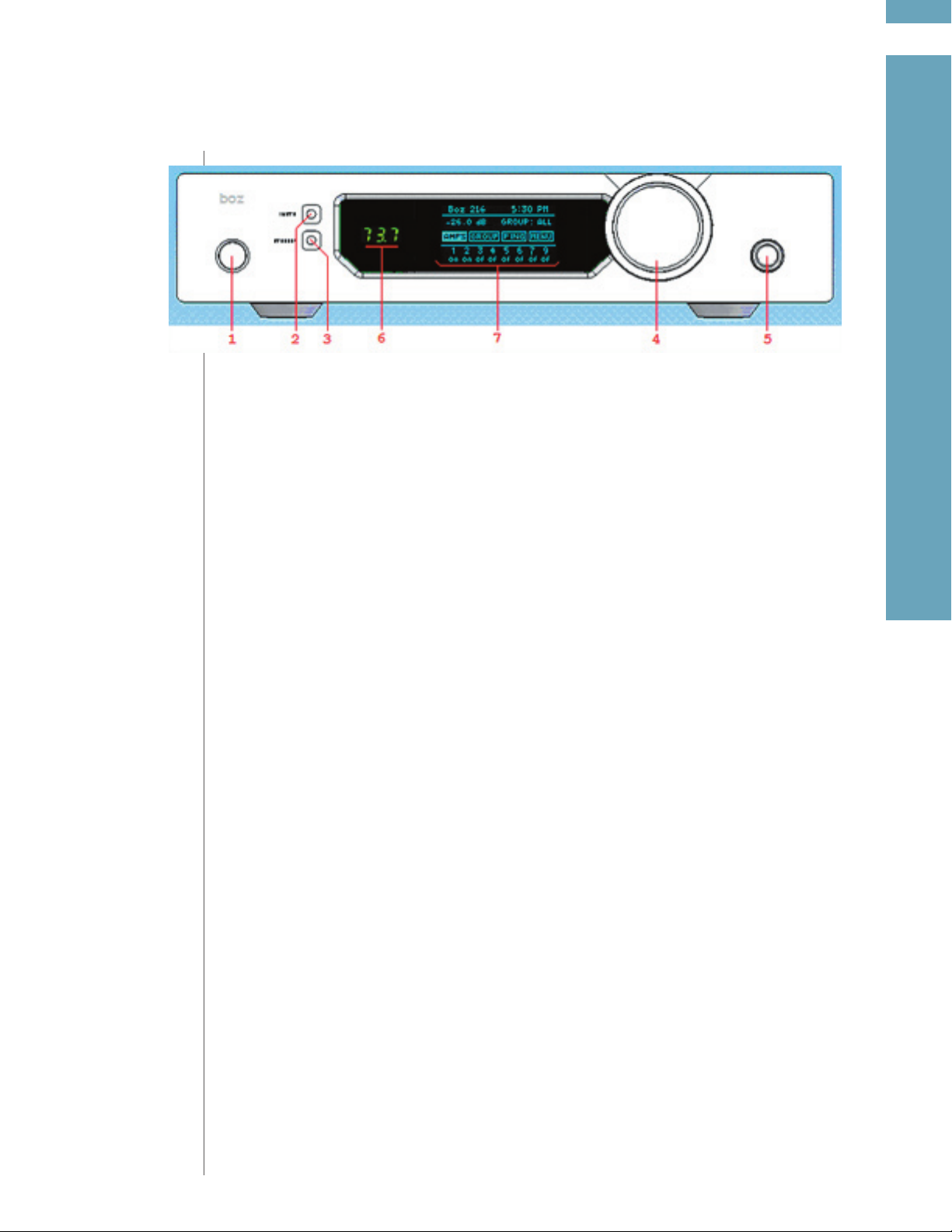
1. Main power switch. Use this switch to turn the BOZ 216/2200 ON and OFF.
2. Mute button. Push this button to mute and un-mute entire system.
3. Standby button. Push this button to place the BOZ-216 into standby mode and to turn it back
on again. When in standby mode, all the BOZ-2200 modules are powered down. However, the
BOZ-216 will not be completely powered down. It will be placed into low power mode
will still be able to receive some IR and RS232 commands.
4. Volume control knob.
5. Rotary control knob. Turn and push this knob to scroll through menu options, change system
parameters and select options.
6. Master level display. Displays the master level form 0.0, the minimum value, to 99.9, the maxi mum value.
7. Main display. All system menus are displayed here.
Before trying to access BOZ 216/2200 via your PC make sure that your system is properly con
nected.
and
-
getting started
16
boz
216/2200
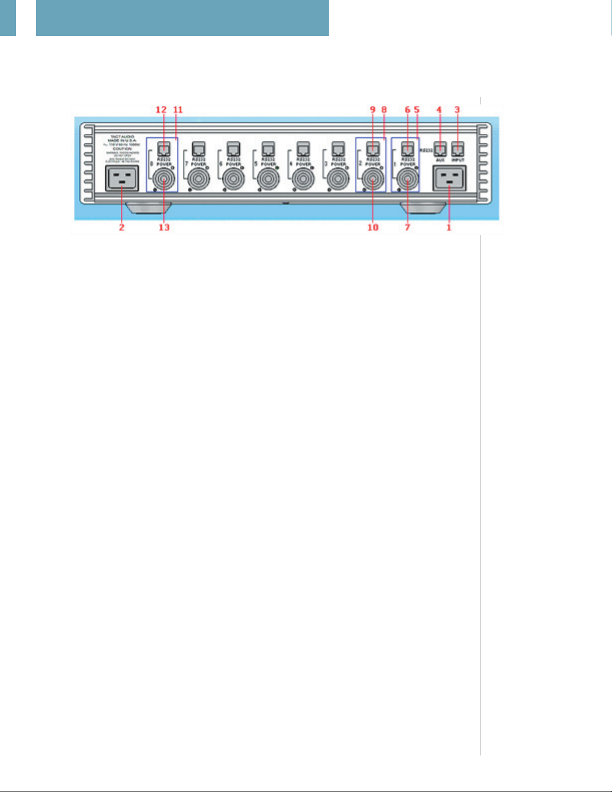
boz - 216 back panel
The back panel connectors consist of two AC power connectors, INPUT and AUX RS232 connectors, and eight blocks of RS232 and power connectors labeled 1 through 8. These blocks are
referred to as BOZ-216 I/O blocks.
1. First AC connector. Note that the BOZ-216 has two AC connectors, one on the left side of
the unit and another one on the right side of the unit. This connector provides
power
2. Second AC connector. This power entry module provides filtered AC power for the BOZ 2200 modules connected to power output connectors 4,5,6 and 7.
3. RS232 connector. This is where your PC, or any other RS232 based controller, should be
connected
4. RS232 connector. This connector is used to pass RS232 signal connected to (3) to other
units, such as the Tact-2.2 X, Tact TCS, and Tact-2.0 S.
5. BOZ-216 I/O block #1.
6. RS232 connector of I/O block #1.
7. Filtered AC POWER connector of I/O block #1.
8. BOZ-216 I/O block #2.
9. RS232 connector of I/O block #2.
10. Filtered AC POWER connector of I/O block #2.
11. BOZ-216 I/O block #8.
12. RS232 connector of I/O block #8.
for the BOZ-2200 modules connected to power connectors 1,2,3 and 4.
filtered AC
RS232:
For more communications information,
please see p. 61.
The first AC Connector
(1) is used for Boz-216
internal logic has to be
connected at all times,
even if I/O blocks 1-4
are not in use.
The second AC Con
nector (2) has to be
connected if any I/O
Blocks 5-8 are being
used.
The I/O Blocks do not
have to be connected
consecutively. They can
be used in any order
and in any combination.
-
13. Filtered AC power connector of I/O block #8.
Each BOZ-2200 module is connected to one of the eight BOZ-216 I/O blocks. The RS232 connec
tor has to be connected to the BOZ-2200 RS232 connector with the supplied six wire cable. The
POWER connector has to be connected to the POWER connector of BOZ-2200 module with the
supplied cable. For proper operation it is necessary to connect both the RS232 and the POWER
connectors to the corresponding BOZ-2200 connectors.
Note: Only the supplied cables can be used to connect BOZ-2200 modules to the BOZ-216 control
unit.
-

boz - 2200 front panel
17
Power Switch:
Information on turning
the modules ON/OFF
via the AMP menu can
be found on p.42.
Peak Detector:
The peak detec
tion level can be set
individually for each
module from its OPT
menu. For more information see p. 59.
Display:
Choosing between
level display and
sampling frequency
display (Fs) is found
on p.48.
Level Display
When editing groups
it is extremely useful to
be able to quickly see
what each module’s
designated AMP
number is. Clearly,
the more modules
you have, the harder
it is to keep track. The
PING command can be
access from the First
Screen and from the
AMPS menu.
-
& PING:
1. Power switch. This switch can be used to turn a BOZ-2200 module OFF. However, it is
recommended that a BOZ-2200 be turned OFF through the BOZ-216 control unit’s front
panel display. Individual BOZ-2200 modules can be turned OFF or ON via the AMP menu. The
power status of the modules is displayed in the bottom row of the First Screen display of the
BOZ-216 control unit.
2. Power LED. When lit indicates that power is applied to a BOZ-2200 module.
3. Input 1 LED. When lit indicates that digital input 1 (XLR - connector, AES/EBU) is selected.
4. Input 2 LED. When lit indicates that digital input 2 (RCA - connector, SPDIF) is selected.
5. External clock LED. When lit, indicates that the external clock is selected. If the external clock is
selected and there is no clock present at the input, this light will flash.
6. Peak detector light. If the digital input signal exceeds the signal threshold level as set in the
corresponding amplifier OPT menu, this light will turn on.
7. Display. Displays either the level or the sampling frequency of the input signal. The level
is shown from a minimum value of 0.0 to a maximum value of 99.9. Choosing between the
two display options is performed through a module’s OPTIONS menu.
Additionally, when a system PING is initiated, this screen will display the AMP number desig nated to the module. The AMP number corresponds to the BOZ-216 I/O block that the mod ule is connected to.
8. Mute light. When lit indicates that the BOZ-2200 is muted.
9. Mute button. Each individual BOZ-2200 module can be mute through its mute button. The
mute button on BOZ-216 control unit’s front panel will mute the entire system.
getting started

18
boz
216/2200216/2200
boz - 2200 back panel
1. Right channel output - negative terminal. Connect this output to the corresponding
loudspeaker input.
2. Right channel output - positive terminal. Connect this output to the corresponding loud speaker input.
3. Digital input 1. This is the modules AES/EBU digital input.
4. Digital input 2. This is the module’s SPDIF digital input.
5. External clock input.
6. RS-232 input. Using the included RS232 cable, connect to a selected BOZ-216 I/O Block.
7. Power connector. Using the included power cable, connect to a selected BOZ-216 I/O
Block.
8. Digital output 1. This an AES/EBU digital pass-through signal.
9. Digital output 2. This an SPDIF digital pass-through signal.
10. Left channel output - negative terminal. Connect this output to the corresponding loud speaker input.
11. Left channel output - positive terminal. Connect this output to the corresponding loud speaker input.
Make sure that a BOZ2200 module’s RS-232
input and Power Connector are connected
to corresponding
connectors within the
same Power Block on
the BOZ-216.
The digital passthrough is
what is
called an electrically
repeated output. It
passes through exactly
what was put into
the inputs. The input
is available for passthrough on both the
AES/EBU and SPDIF
digital pass-through
outputs on the back
panel; you pick which
one you want to use.
The pass-through
signals is not affected
by any internal signal
processing, such as
level, polarity, etc...
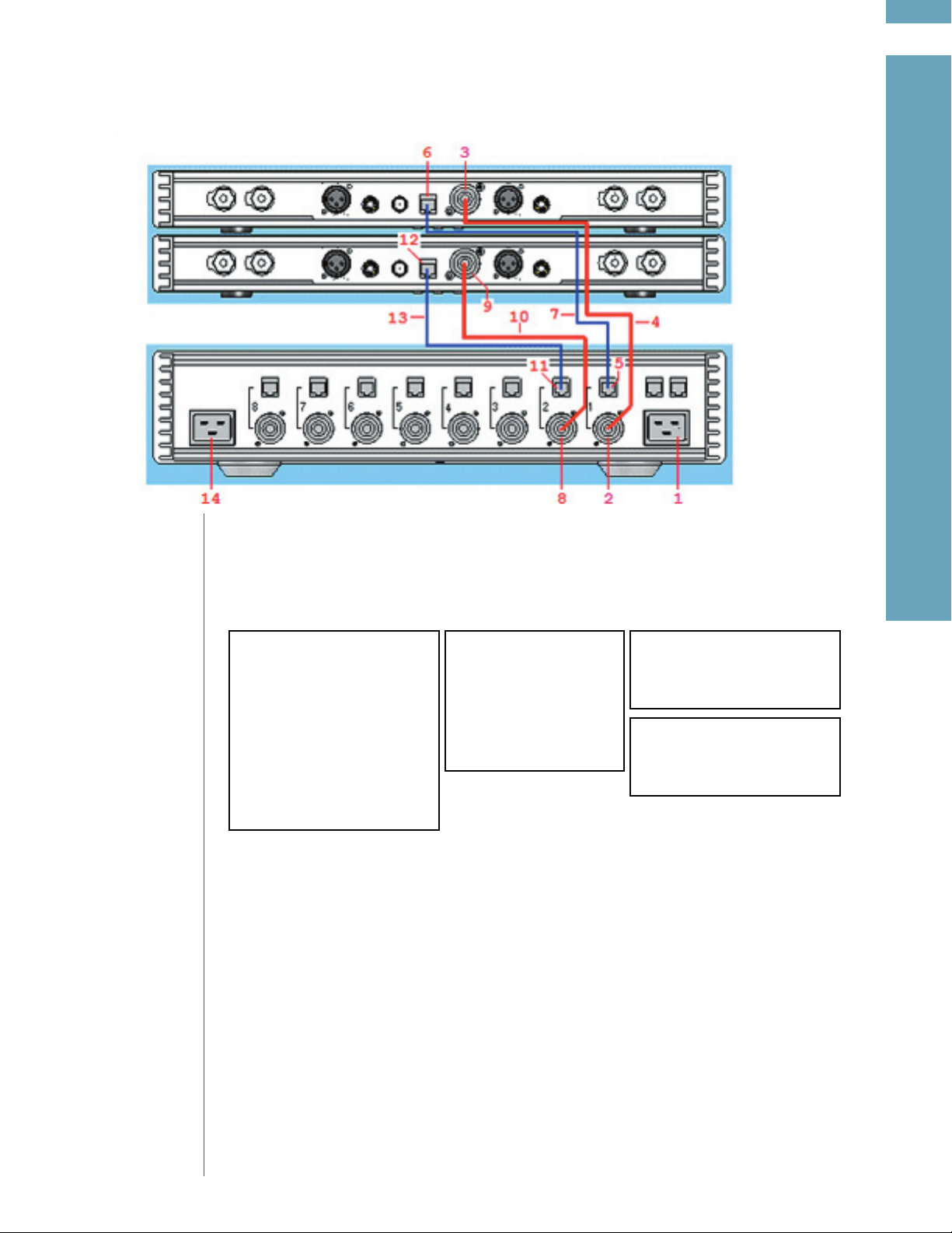
connecting boz-2200 to boz-216
19
getting started
This connection
example is for a Boz
system that consists
of two BOZ-2200
amplification modules,
for a total of four channels of amplification.
Connection procedures
for systems that
consist of additional
BOZ-2200 modules are
easily extrapolated.
Always turn the power off first before making any new connections or changes to existing connections.
Power-off by using the BOZ-216 main power switch and then disconnect the two supplied AC power
cords from the wall power outlet. When connections or changes to the existing connections are completed, plug the AC power cords into the wall outlet and then turn the main BOZ-216 power switch on.
BOZ-216 Master Unit
(1) AC Power Connector for
blocks 1-4
(2) Block-1 AC power connector
(5) Block-1 RS232 connector
(8) Block-2 AC power connector
(11) Block-2 RS232 connector
(14) AC Power Connector for
blocks 5-8
1. Connect AC power to this connector. Note that in this example there are only two BOZ-2200
modules and that they are connected to power blocks 1 and 2. Since power blocks 1-4 are
powered by the transformer connected to AC power through this connector(1), there
is no need to use the other AC connector (14).
2.
Power Block-1 Connections:
A) Use the supplied cable (4) to connect the power block (2) to the module’s power connec tor (3).
B) Use the supplied RS232 cable (7) to connect the power block’s RS232 connector (5) to the
module’s RS232 connector (6).
Cables
(4) Supplied power cable
(7) Supplied RS232 cable
(10) Supplied power cable
(13) Supplied RS232 cable
BOZ-2200 Module 1
(3) BOZ-2200 power connector
(6) BOZ-2200 RS232 connector
BOZ-2200 Module 2
(9) BOZ-2200 power connector
(12) BOZ-2200 RS232 connector
3.
Power Block-2 Connections:
A) Use the supplied cable (10) to connect the power block (8) to the module’s power con nector (9).
B) Use the supplied RS232 cable (13) to connect the power block’s RS232 connector (11) to
the module’s RS232 connector (12).

20
boz
216/2200216/2200216/2200
remote control

21
To use the remote
control, you must first
ENABLE IR Control.
This is done
OPTIONS menu. The
OPTIONS menu is
accessed from the First
Screen by selecting
the MENU option. For
more information on
the OPTIONS menu,
see p. 54.
Arrow Keys:
The navigational arrow
keys on the remote
correspond in func
tionality to the Optical
Control Knob found on
the front panel of the
BOZ-216 control unit.
For detailed navigation
instructions, see p. 28.
in the
-
1-STANDBY
The STANDBY button will turn the BOZ-216/2200 “ON” or it will place it into “STANDBY” mode. When
in standby mode, the unit is placed into a lower power “idling’ state.
2-DIGITAL
The DIGITAL button is not used with this unit.
3-ANALOG
The ANALOG button is not used with this unit.
4-CORRECTION block
The CORRECTION buttons are not used with this unit.
5-MENU
The MENU button will switch the front panel display from the status screen to the main menu
screen.
6-VIDEO
The VIDEO button is inactive with this unit.
getting started
7-UP
The UP navigational button is used to select menu options and/or to change their values.
8-DOWN
The LEFT navigational button is used to select menu options and/or to change their values.
9-LEFT
The LEFT navigational button is used to select menu options and/or to change their values.
10-RIGHT
The RIGHT navigational button is used to select menu options and/or to change their values.
11-ENTER
The ENTER button will select the menu option currently marked by the blinking cursor. It is also
used to enter an edited parameter.
12-VOLUME Block
The VOLUME block consists of three buttons.
The MUTE button will mute/un-mute all enabled channels.
The UP button will increase the master volume level.
The DOWN button will decrease the master volume level.
 Loading...