

Page 1
Installation and Operation Manual
Due to the dynamic nature of product design, the information contained in this
document is subject to change without notice. Broadcast Tools, Inc., assumes no
responsibility for errors and/or omissions contained in this document. Revisions
of this information or new editions may be issued to incorporate such changes.
Broadcast To ols® is a registered t rademark of Broadcast Tools, Inc.
Copyright, 1989 - 2013 by Broadcast Tools, Inc. All rights reserved.
No part of this document may be reproduced or distributed without permission.
Visit www.broadcasttools.com for important product update information.
Manual Update: 06/25/2013
FlexPhones Master
INC
®
Page 2

e-mail:
support@broadcasttools.com
voice:
360.854.9559
fax:
866.783.1742
FlexPhones Master Installation and Operation Manual
Table of Contents
Section Title Page #
Introduction. . . . . . . . . . . . . . . . . . . . . . . . . . . . . . . . . . . . . . . . . . . . . . . . . . . . . . . 3
Safety Information . . . . . . . . . . . . . . . . . . . . . . . . . . . . . . . . . . . . . . . . . . . . . . . . . 3
Who to Contact for Help . . . . . . . . . . . . . . . . . . . . . . . . . . . . . . . . . . . . . . . . . . . . 3
Product Description . . . . . . . . . . . . . . . . . . . . . . . . . . . . . . . . . . . . . . . . . . . . . . . . 4
Additional Features. . . . . . . . . . . . . . . . . . . . . . . . . . . . . . . . . . . . . . . . . . . . . . . . . 4
Installation . . . . . . . . . . . . . . . . . . . . . . . . . . . . . . . . . . . . . . . . . . . . . . . . . . . . . . . 5
Operation. . . . . . . . . . . . . . . . . . . . . . . . . . . . . . . . . . . . . . . . . . . . . . . . . . . . . . . . . 8
Specifications . . . . . . . . . . . . . . . . . . . . . . . . . . . . . . . . . . . . . . . . . . . . . . . . . . . . . 9
Warranty . . . . . . . . . . . . . . . . . . . . . . . . . . . . . . . . . . . . . . . . . . . . . . . . . . . . . . . . 10
Functional Diagram. . . . . . . . . . . . . . . . . . . . . . . . . . . . . . . . . . . . . . . . . . Appendix
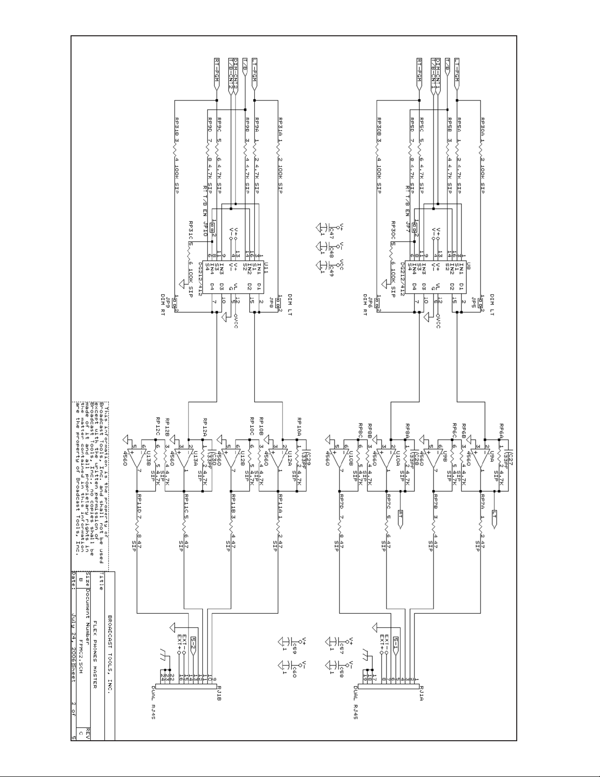
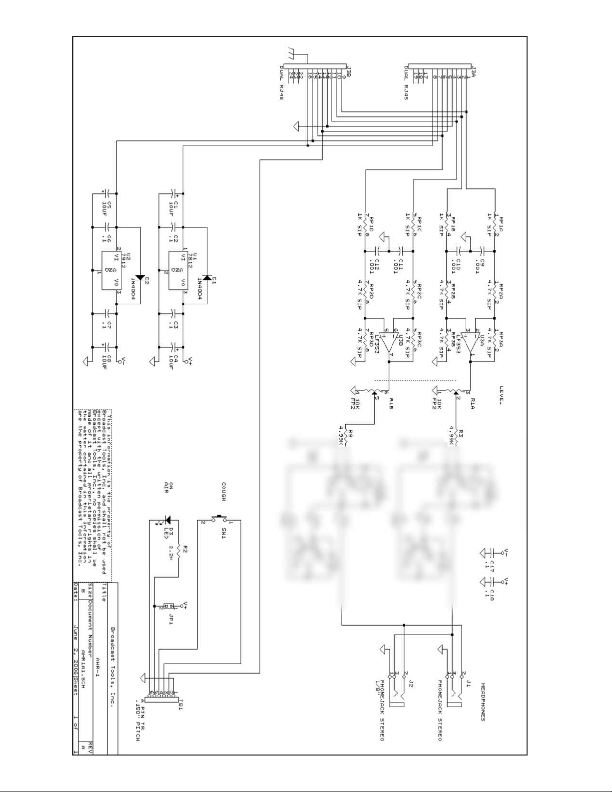
Schematic and Component Layout . . . . . . . . . . . . . . . . . . . . . . . . . . . . . . Appendix
Jumper Layout. . . . . . . . . . . . . . . . . . . . . . . . . . . . . . . . . . . . . . . . . . . . . . Appendix
Installation Example . . . . . . . . . . . . . . . . . . . . . . . . . . . . . . . . . . . . . . . . . Appendix
WEBSITE:
Visit our web site for
product updates and
additional information.
2
CONTENTS
Page 3

e-mail:
support@broadcasttools.com
voice:
360.854.9559
fax:
866.783.1742
3
FlexPhones Master Installation and Operation Manual
INTRODUCTION
INTRODUCTION
Thank you for your purchase of a Broadcast Tools® FlexPhones Master multi-user
headphone system (referred to as the FlexPhones Master or Master throughout this
manual). We’re confident that this product will give you many years of dependable
service. This manual is intended to give you all the information needed to install and
operate the Broadcast Tools® FlexPhones Master.
SAFETY INFORMATION
Only qualified personnel should install Broadcast Tools® products. Incorrect or
inappropriate use and/or installation could result in a hazardous condition.
Broadcast Tools, Inc., is unable to support NON-Broadcast Tools software, hardware or
NON-Broadcast Tools computer/hardware/software problems. If you experience these
problems, please research your hardware/software instruction manuals or contact the manufacturers technical support department.
WHO TO CONTACT FOR HELP
If you have any questions regarding your product or you need assistance, please contact your distributor from whom you purchased this equipment.
If you would like more information about Broadcast Tools® products, you may
reach us at:
Broadcast Tools, Inc.
131 State Street
Sedro-Woolley, WA 98284-1540 USA
Voice: 360 . 854 . 9559
Fax: 866 . 783 . 1742
Internet Home Page: www.broadcasttools.com
E-mail: support@broadcasttools.com
THANK YOU FOR CHOOSING
BROADCAST TOOLS® BRAND PRODUCTS!
CAUTION!
Broadcast Tools®
Products, as with any
electronic device, can
fail without warning.
Do not use this product
in applications where a
life threatening condition
could result due to failure.
NOTE:
This manual should be
read thoroughly before
installation and operation.
WEBSITE:
Visit our web site for
product updates and
additional information.
Page 4

e-mail:
support@broadcasttools.com
voice:
360.854.9559
fax:
866.783.1742
4
FlexPhones Master Installation and Operation Manual
DESCRIPTION
Product Description:
The FlexPhones Master is a professional Broadcast/Studio six channel distributed headphone system with independent talkback capabilities. Each of the six
channels provides stereo program monitoring and selective talkback with interconnection via CAT5 cable to multiple Active Headphone Remotes (AHR-1) and/or the
Monitor Selector Interface (MSI). Multiple masters may be cascaded to form larger systems. The FlexPhones Master is equipped with inputs for stereo program and
talkback audio. Rear panel program and talkback trimmers are provided to pre-set
maximum input levels. The microphone/line level talkback input is available via a
rear panel plug-in euroblock connector, while the front panel XLR connector facilitates the use of a user provided gooseneck microphone or headset. The front panel
is equipped with a level control for local headphones with both 1/4” and 1/8” stereo
headphone jacks. The six front panel talkback switches allow the user to independently communicate with each AHR-1 listener and can be configured to insert talkback audio into only the left or both ears and dim either or both program channels.
Any combination of switches may be pressed, while the “All-Call” interrupts all listeners. The Talkback function can be remotely controlled. Six RJ45 jacks are provided to distribute audio and power via CAT5 cable to the AHR-1’s, and/or MSI’s
that conform to the StudioHub+ wiring format. Low-Z balanced audio distribution
is used to preclude audio degradation with long cable runs.
Additional features include:
Front panel power and talkback LED indicators, surge protected internal bipolar 24/15-vdc-power supply affording superior headroom and high definition
audio. The optional Monitor Selector Interface (MSI) provides transparent audio
switching of the program and talkback functions into a studio’s monitor system. The
MSI is inserted between a studio’s air or console’s monitor feed and monitor amplifier. The MSI may be connected to the FlexPhones Master or AHR-1. All audio
connections are balanced and supplied on plug-in euroblock screw terminals.
The FlexPhones Master half rack profile, allows the unit to be set on a desktop, mounted on a wall or the RA-1, Rack-Able mounting shelf. The AHR-1 may
be desktop mounted, under counter or with the optional HR-1/MP or HR-1/MP-XLR
mounting plates, which may be turret mounted.
WEBSITE:
Visit our web site for
product updates and
additional information.
Page 5

e-mail:
support@broadcasttools.com
voice:
360.854.9559
fax:
866.783.1742
5
FlexPhones Master Installation and Operation Manual
INSTALLATION
Installation:
Please examine your FlexPhones Master and/or AHR-1 carefully for any
damage that may have been sustained during shipping. If any is noted, please notify the shipper immediately and retain the packaging for inspection by the shipper.
The package should contain the FlexPhones Master, 16vac@600ma wall power
transformer, two CAT5 cables and this manual.
Installation of the FlexPhones Master in high RF environments should be
performed with care. Shielded cable is suggested for all audio connections.
All shields should be tied to the EGND terminals. The station ground should
be connected to the chassis ground screw located on the far right side of the
FlexPhones Master as viewed from the rear. It is recommended that all cables connected to the FlexPhones Master be looped through ferrite cores to suppress RF.
Surge protection with RF filtering is also suggested for the wall transformer. The
purchase of an inexpensive UPS will provide back up in case of power outages.
Connections are via plug-in euroblock connectors and RJ45 connectors.
Remove the connector from the header; remove about 1/8” of insulation from each
wire. Insert the wire into the desired terminal and then tighten the screw. Be sure
no bare wires are exposed. Reinstall the connectors.
Stereo Program Input
Normal program audio should be connected to the + and - inputs for balanced operation, or to the + input and grounding the - side for unbalanced input operation on
TB1 (bottom). Audio levels should be between -15 and +4dBu.
Talkback Audio Input
Mic or line level audio should be connected to the + and - inputs for balanced operation, or to the + input and grounding the - side for unbalanced input operation on
either TB1 (top) or the front panel XLR connector. Audio levels should be between
–60 and –30dBu in MIC position or –15 and +4dBu in LINE position. JP1 and JP2
are used to set the talkback input for either MIC or LINE levels. Follow the jumper
layout in the appendix to set these two jumpers to the desired position. The factory
default is set to MIC.
Talkback Audio Output
The unbalanced output can be used to feed additional FlexPhones Master
talkback inputs. Connections to TB1 (top) can be made to the + output and ground
for unbalanced output operation.
NOTE:
For proper installation,
follow the silkscreen
labels on the rear
panel.
WEBSITE:
Visit our web site for
product updates and
additional information.
Page 6

e-mail:
support@broadcasttools.com
voice:
360.854.9559
fax:
866.783.1742
6
FlexPhones Master Installation and Operation Manual
INSTALLATION
DIM jumper configuration
Removing either or both of the Dim jumpers mutes the program audio during a talkback session, while inserting either or both will dim the program audio
approximately 20db below normal program levels. Use the table below along with
the jumper layout sheet in the appendix to properly configure. Factory defaults have
these jumpers installed.
Right ear talkback enable jumper:
In a talkback session, talkback audio is always feed into the left ear. Placing
a jumper over the desired header will enable talkback audio in the right ear. Use the
table below along with the jumper layout sheet in the appendix to properly configure. Factory default has these jumpers installed.
Function Chnl 1 Chnl 2 Chnl 3 Chnl 4 Chnl 5 Chnl 6
LT Dim JP5 JP8 JP11 JP14 JP17 JP20
RT Dim JP6 JP9 JP12 JP15 JP18 JP21
RT T/B Enable JP7 JP10 JP13 JP16 JP19 JP22
Auxiliary Remote/Local jumper set-up
We provide the wire attached to pin 5 of each RJ45 for use by the
user. The wire terminates on a three-position header. The header is labeled JPxx.
The factory default is set to Remote. Use the table below along with the jumper layout sheet in the appendix to properly configure.
Function RMT 1 RMT 2 RMT 3 RMT 4 RMT 5 RMT 6
JP24 JP26 JP28 JP30 JP32 JP34
Remote 1 & 2 1 & 2 1 & 2 1 & 2 1 & 2 1 & 2
Local 2 & 3 2 & 3 2 & 3 2 & 3 2 & 3 2 & 3
Remote Control input jumper set-up
Each optically isolated input is equipped with a four-position header.
The header is labeled JPxx. The factory default is set for a DRY (5 vdc source) input
(switch, contact, open collector) with a jumper between 1 & 2 and another jumper
over 3 & 4. To change the input to WET (user supplied voltage between 5 and
24vdc), remove both jumpers and place ONE jumper over pins 2 & 3. Use the table
below along with the jumper layout sheet in the appendix to properly configure.
! NOTE: Refer to the schematic diagram for the proper polarity when attaching
equipment to each input.
Function RMT 1 RMT 2 RMT 3 RMT 4 RMT 5 RMT 6 All-Call
JP23 JP25 JP27 JP29 JP31 JP33 JP35
Wet
A = Anode A = Anode A = Anode A = Anode A = Anode A = Anode A = Anode
2 & 3 B = Cath B = Cath B = Cath B = Cath B = Cath B = Cath B = Cath
Dry A = Gnd A = Gnd A = Gnd A = Gnd A = Gnd A = Gnd A = Gnd
1 & 2 / 3 & 4 B = Cath B = Cath B = Cath B = Cath B = Cath B = Cath B = Cath
WEBSITE:
Visit our web site for
product updates and
additional information.
Page 7

e-mail:
support@broadcasttools.com
voice:
360.854.9559
fax:
866.783.1742
7
FlexPhones Master Installation and Operation Manual
INSTALLATION
Cable Interconnection
After completion of the jumper set-up and the audio connections have been made,
connection of the CAT5 cable can be started. Connect the user supplied CAT5 cable
between the desired channels (follow the numbers on the chassis) rear panel RJ45
on the FlexPhones Master and each AHR-1 and/or MSI. Up to two AHR-1’s or one
AHR-1 and one MSI can be daisy-chained from each RJ45 on the Master.
Program Level Setup
Turn the rear panel “Master Pgm Lvl” trimmer CCW. Set all headphone
level controls to 1 o’clock. Plug a set of headphones in to either of the AHR-1’s
headphone jacks. Feed the desired program level into the Master and adjust R2 the
rear panel “Master Pgm Lvl” trimmer for the desired level. This also holds true for
the MSI.
Talkback Level Setup
Turn the rear panel “T/B Lvl” trimmer CCW. Plug a set of headphones in to
either of the AHR-1’s headphone jacks. Hold down the talkback channel button that
the AHR-1 is connected to and adjust the “T/B Lvl” trimmer R21 on the rear panel
of the master for the appropriate talkback level. Depending on the configuration for
each channel, the program audio will be muted or dimmed in each ear, while the
talkback will be present on either or both ears. This also holds true for the MSI.
Microphone Phantom Power Jumper
To power microphones needing phantom power; install the supplied jumper
over JP36. JP36 is supplied but not installed. 15vdc is supplied when installed.
Page 8

e-mail:
support@broadcasttools.com
voice:
360.854.9559
fax:
866.783.1742
8
FlexPhones Master Installation and Operation Manual
OPERATION
Operation:
To call any combination of AHR-1’s press the desired front panel talkback
button(s) or the ALL CALL button. You may also do the same using user supplied
momentary normally open dry contact switches connected across each of the rear
panel remote control inputs.
The Front panel headphone jacks and level control only monitor program.
Only one set of headphones should be used.
NOTE: The talkback feature may be added by reconfiguring internal jumpers.
Consult the factory before making this change.
NOTE: 8 ohm and/or monaural headphones should not be used with these products.
WEBSITE:
Visit our web site for
product updates and
additional information.
Page 9

e-mail:
support@broadcasttools.com
voice:
360.854.9559
fax:
866.783.1742
9
FlexPhones Master Installation and Operation Manual
SPECIFICATIONS
Specifications:
Program Input Level -15 to +4 dBu. MIL+24dBu, balanced, bridging 10k Ω.
Talkback Input Level -60 to -30 dBu MIC / -15 to +4dBu LINE, balanced.
Microphone phantom power +15vdc.
Gain 6 dB.
Frequency Response 10 to 20 kHz; +/- .0.25dB
Signal/Noise Ratio >85 dB nominal, weighted 10 to 22Khz.
Distortion 0.005% THD, nominal.
IMD (250/7kHz) 0.005% IMD, nominal.
Headphone Output 24 to 600 W headphones. 200mw nominal.
Switching Method Professional level analog switch arrays.
Logic CMOS.
Operation Control Front Panel - Momentary switches.
Remote - Optically isolated (5 to 24vdc) wet or dry.
Default = Dry (5 volt internally sourced)
Status/Control Front Panel - LED indicators.
Interfacing Master audio & remote rontrol - Rear panel euroblock
removable screw terminals with mating connectors and
female XLR.
AHR-1 power, audio and control - RJ45 connectors and
plug-in euroblock screw terminals.
MSI power, audio and control - RJ45 connectors and plugin euroblock screw terminals.
Wiring conforms to the StudioHub+ format.
Power 16 Vac @ 600 ma, 120 Vac 50-60 Hz power transformer.
Supplied. (CE 240 Vac 50-60 Hz optional)
Mechanical Master - 8.50” x 1.55” x 6.00” (WHD) / Weight: 3.0 lbs.
AHR-1 – 3.70” x 1.55” x 3.50” (WHD) / Weight: 1.0 lbs
Options Master - RA-1, 1 RU rack Shelf. Hold two units.
AHR-1 - HR-1/MP, mounting panel
AHR-1 - HR-1/MP-XLR, mounting plate with XLR connector
hole.
MSI, Monitor Selector Interface.
WEBSITE:
Visit our web site for
product updates and
additional information.
Page 10

10
FlexPhones Master Installation and Operation Manual
LIMITED WARRANTY
LIMITED WARRANTY
The term “Buyer” as used in this document refers to and includes both (but only) (a) any person or entity who acquires such an item for
the purpose of resale to others (i.e., a dealer or distributor of an item), and (b) the first person or entity who acquires such an item for
such person’s or entity’s own use.
Broadcast Tools warrants to each Buyer of any item manufactured by Broadcast Tools that the item will be free from defects in materials and workmanship at the time it is shipped by Broadcast Tools if the item is properly installed, used and maintained.
EXCLUSIVE REMEDIES
If Broadcast Tools is notified, in writing, of a failure of any item manufactured by Broadcast Tools to conform to the foregoing Limited
Warranty within one (1) year following the date of the Buyer’s acquisition of the item, and if the item is returned to Broadcast Tools in
accordance with Broadcast Tools’ instructions for confirmation by inspection of the defect (which at Broadcast Tools’ election may
include, without limitation, a requirement that the Buyer first obtain a Return Authorization number from Broadcast Tools, that the Buyer
furnish proof of purchase in the form of an invoice and/or receipt, and that the Buyer prepay all freight charges associated with any return
of the item to Broadcast Tools using such freight service as Broadcast Tools reasonably may specify), Broadcast Tools will repair or
replace the defective item, or will refund the purchase price paid by the Buyer for the item. Broadcast Tools shall have the exclusive
right to choose between these alternative remedies.
NO OTHER WARRANTIES OR REMEDIES
TO THE MAXIMUM EXTENT PERMITTED BY APPLICABLE LA W , BROADCAST TOOLS AND ITS SUPPLIERS DISCLAIM ALL OTHER
WARRANTIES, EITHER EXPRESS OR IMPLIED, INCLUDING BUT NOT LIMITED TO IMPLIED WARRANTIES OF MERCHANTABILITY OR FITNESS FOR A PARTICULAR PURPOSE; AND THE FOREGOING ALTERNATIVE REMEDIES SHALL BE EXCLUSIVE OF
ALL OTHER REMEDIES. THIS LIMITED WARRANTY GIVES YOU SPECIFIC LEGAL RIGHTS. YOU MAY HAVE OTHER RIGHTS,
WHICH VARY FROM STATE/JURISDICTION TO STATE/JURISDICTION.
NO LIABIL ITY FOR CONSEQUENTIA L DA MAGES
TO THE MAXIMUM EXTENT PERMITTED BY APPLICABLE LAW, NEITHER BROADCAST TOOLS NOR ANY OF ITS SUPPLIERS
SHALL HAVE ANY LIABILITY FOR ANY SPECIAL, INCIDENTAL, INDIRECT, CONSEQUENTIAL OR PUNITIVE DAMAGES WHATSOEVER (INCLUDING, WITHOUT LIMITA TION, ANY DAMAGES FOR LOST PROFITS, BUSINESS INTERRUPTION, LOSS OF DATA OR
INFORMATION, COST OF CAPITAL, CLAIMS OF CUSTOMERS, OR ANY OTHER PECUNIARY LOSS) ARISING OUT OF THE USE
OF OR THE INABILITY TO USE ANY ITEM SUPPLIED BY BROADCAST TOOLS, EVEN IF BROADCAST TOOLS HAS BEEN
ADVISED OF THE POSSIBILITY OF SUCH DAMAGES HAVE ANY LIABILITY FOR ANY SPECIAL, INCIDENTAL, CONSEQUENTIAL,
EXEMPLARY OR PUNITIVE DAMAGES. THIS LIMITATION OF LIABILITY APPLIES WHETHER A CLAIM IS ONE ALLEGING
BREACH OF A CONTRACT OR WARRANTY, NEGLIGENCE OR OTHER TORT, FOR THE VIOLATION OF ANY STATUTORY DUTY,
THE FAILURE OF ANY LIMITED OR EXCLUSIVE REMEDY TO ACHIEVE ITS ESSENTIAL PURPOSE, OR ANY OTHER CLAIM OF
ANY NATURE. BECAUSE SOME STATES AND JURISDICTIONS DO NOT ALLOW THE EXCLUSION OR LIMITATION OF LIABILITY
FOR INCIDENTAL OR CONSEQUENTIAL DAMAGES, THIS LIMITATION MAY NOT APPLY TO YOU.
Broadcast Tools, Inc.
131 State Street
Sedro-Woolley, WA 98284 • USA
360.854.9559
voice • 866.783.1742 fax
support@broadcasttools.com e-mail
www.broadcasttools.com website
e-mail:
support@broadcasttools.com
voice:
360.854.9559
fax:
866.783.1742
Page 11

APPENDIX
e-mail:
support@broadcasttools.com
voice:
360.854.9559
fax:
866.783.1742
FlexPhones Master Installation and Operation Manual
Page 12

Page 13
Page 14

Page 15

Page 16

Page 17
Page 18

Page 19

* Chnl 5
* Chnl 6
* Chnl 3
* Chnl 4
* Chnl 1
* Chnl 2
MIC Phantom
Power Jumper
Chnl 1
RMT
Remote Control
Connectors
Chnl 2
RMT
Chnl 3
RMT
Chnl 4
RMT
Chnl 5
RMT
Chnl 6
RMT
All-Call
RMT
TOP
Talkback Input/Output
BOTTOM
Left & Right Program Inputs
Power
16VAC @ 600MA
CAT 5 to remote
Headphone Amplifier
or AHR-1
MIC/Line
Gain Set
* = Right Talk &
Left/Right DIM Jumpers
131 State Street, Sedro-Woolley, WA 98284 USA • 360.854.9559 • Fax 866.783.1742
Visit us online at www.broadcasttools.com
Copyright © 1989-2007 by Broadcast Tools, Inc. All Rights Reserved.
Broadcast Tools® FlexPhones Master
Jumper Layout
Appendix
LL M L M L M M
Modification Date: 07/13/07
Page 20

e-mail:
support@broadcasttools.com
voice:
360.854.9559
fax:
866.783.1742
20
FlexPhones Master Installation and Operation Manual
APPENDIX
 Loading...