

Page 1
TAC
1354 Clifford Avenue
P. O. Box 2940
Loves Park, IL 61132-2940
www.tac.com
Application
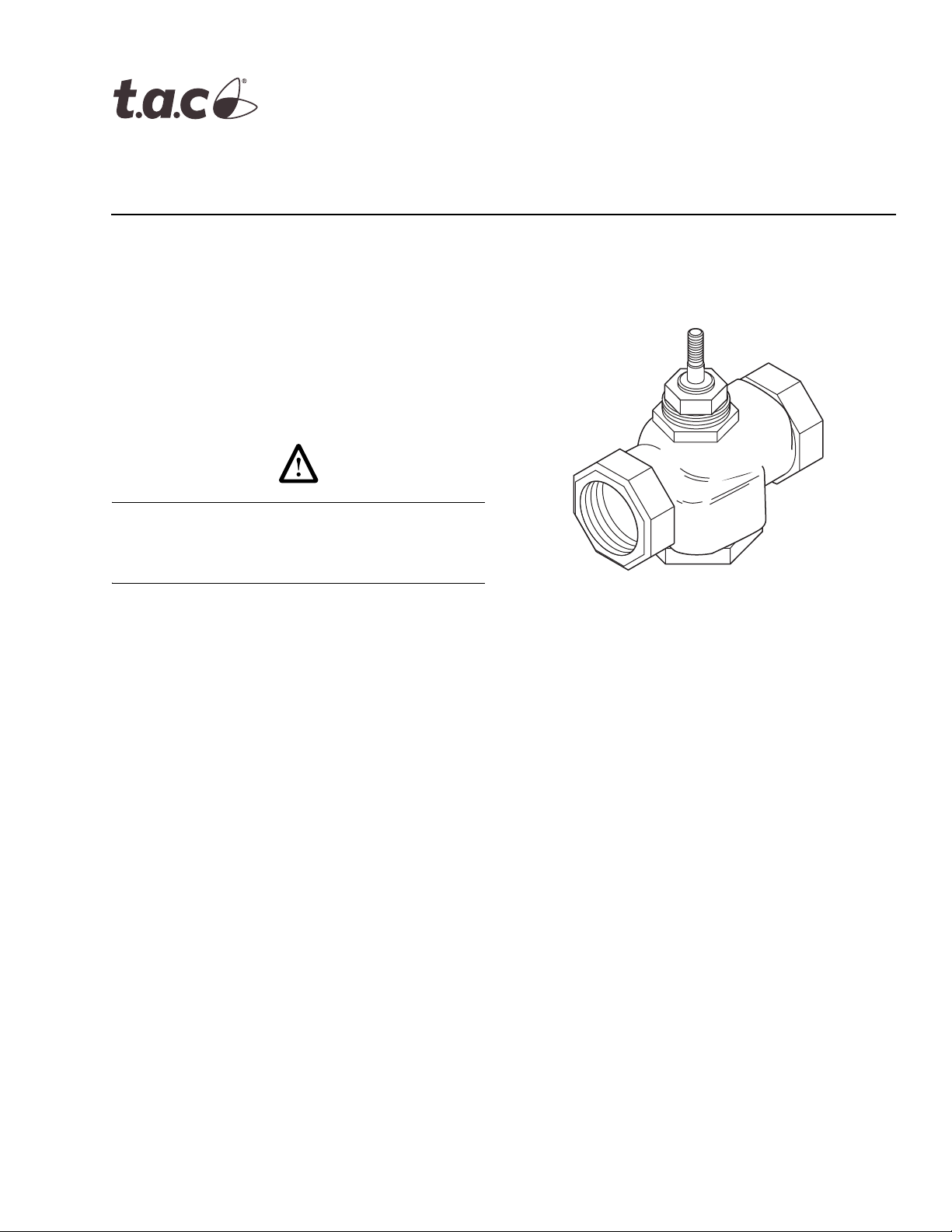
VB-7313 series three-way mixing valves control hot or
chilled water in heating or air conditioning systems.
These valves must be piped with two inlets (“A” and “B”
ports) and one outlet (“AB” port). They are used for
two-position or proportional control applications. Valve
assemblies require an actuator and a valve linkage that
must be purchased separately.
Danger: Do not use for combustible gas applications. The VB-7313 series valve packings are not rated for combustible gas applications, and if used in these applications, gas leaks and explosions could result.
VB-7313 Series
1/2" to 2" Screwed NPT
Three-Way Mixing Valves
General Instructions
Features
• Valve sizes 1/2" to 2"
• 250 psig pressure rating per ANSI Standards
(B16.15–1985) for screwed cast bronze bodies
• Spring-loaded TFE packing
• American Standard Taper Pipe Thread (NPT)
connections
Applicable Literature
• TAC Valve Products Catalog, F-27414
• TAC Electric-Electronic Products Catalog, F-27382
• TAC Pneumatic Products Catalog, F-27383
• CA-28 Control Valve Sizing, F-13755
• Valve Selection Chart for Water, F-11080
• EN-205 Water System Guidelines, F-26080
• Vx-7xxx-8xx, Vx-7xxx-59x, Vx-9xxx-8xx,
Vx-9xxx-59x Globe Valve Assemblies with TAC
DuraDrive Linear Series Actuators, F-26752
Printed in U.S.A. 10-07 © Copyright 2007 TAC All Rights Reserved. F-26074-2
Page 2
SPECIFICATIONS
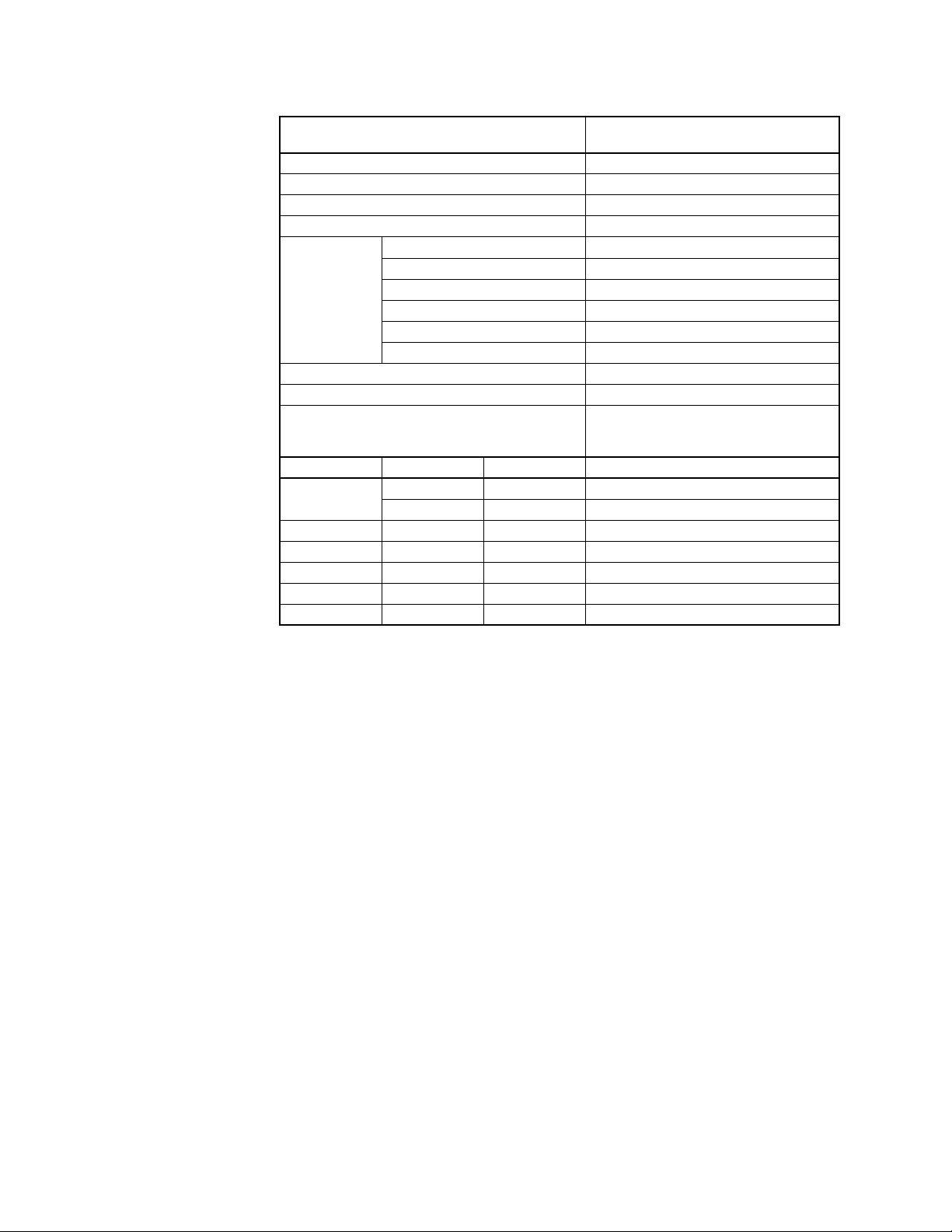
Table-1 Specifications/Models.
Specifications
Valve Body Series
VB-7313-0-4-P
Service Chilled or Hot Water
Flow Characteristics (Figure-1) Mixing
Sizes 1/2" to 2"
Type of End Fitting NPT
Body Bronze
Seat Bronze
Valve
Materials
Stem Stainless Steel
Plug Brass
Packing Spring-loaded TFE
Disc None
ANSI Pressure Class (Figure-2) 250 (up to 400 psig below 150°F)
a
Allowable Control Media Temperature 20 to 281°F (-7 to 138°C)
35 psi (241 kPa) Max. for Normal Life
(refer to “Cavitation Limitations on Valve
Allowable Differential Pressure for Water
b
Pressure Drop” on page 6)
Valve S ize Cv Rating kvs Rating
1/2"
2.2 1.9 VB-7313-0-4-2
4.4 3.8 VB-7313-0-4-4
c
Complete Valve Body Part Number
3/4" 7.5 6.5 VB-7313-0-4-6
1" 14 12 VB-7313-0-4-8
1-1/4" 20 17 VB-7313-0-4-9
1-1/2" 28 24 VB-7313-0-4-10
2" 41 35 VB-7313-0-4-11
a
Do not apply above pressure rating to piping system.
b
Maximum recommended differential pressure. Do not exceed recommended differential pressure (pressure
drop) or integrity of parts may be affected. Exceeding maximum recommended differential pressure voids
product warranty.
c
kvs = m3/h (ΔP = 100 kPa) Cv = kvs x 1.156
Close-off Pressure Rating
The close-off pressure rating is dependent on the size of the valve, valve linkage, and
actuator. Consult the TAC Valve Products Catalog, F-27414, for close-off ratings.
2 © Copyright 2007 TAC All Rights Reserved. F-26074-1
Page 3
Spring Return Position of Valve Assembly
For a valve assembly (valve, linkage, and actuator) to have a spring return position, the
actuator must be of the spring return type. See Table-2 for spring return position of valve
assemblies.
Table-2 Required Compatible Actuators/Linkages.
Actuator Series Required Valve Linkage Spring Return Position
M400A, M800A, M1500A AV-811 (M1500 only) None
MA51-710x, MF51-7103, MS51-7103 Included with Actuator Stem Up
MA51-720x, MF51-7203, MS51-7203 Included with Actuator Stem Up
MA-318, MA-418, MA-419 AV-39 1 Stem Up or Down
MA-5210, MA-5211, MA-5213 AV-7600-1
MC-351, MC-431, MC-4311, MC5-4311 AV-39 3 None
MF-5413, MF-5513 AV-7600-1 & AV-601 Stem Up
MF-22203, MF-22303, MF-22323
MF-63103, MF-63123
MK-2690 AV-74 00
MK-6601, MK-6611, MK-6621 AV-43 0
MM-400, MMR-400
MM-500, MMR-500 Stem Up or Down
MP-361, MP-461-600, MP-465, MP5-4651
MP-371, MP-471-600, MP-475, MP5-4751 Stem Up
MP-381, MP-382, MP-481-600, MP-485,
MP-486, MP-4851, MP5-4851
MP-5210, MP-5211, MP-5213 AV-7600-1
MP-5513
MPR-5610, MPR-5611, MPR-5613
MPR-5713
MS-22353 Included w/Actuator None
a
Stem Up = Flow port “B” to port “AB”. Stem Down = Flow port “A” to port “AB.”
b
High ambient temperatures with high media temperatures in the valve may require the use of AV-601 in addition
to AV-7600. See General Instructions for AV-7600-1 (F-26235) and AV-601 (F-19069) for details.
Included with Actuator None
AV-630 or
AV-630-10
AV-39 1
AV-39 3 None
AV-7600-1 & AV-601
AV-7600-1 & AV-601 Stem Up
b
b
Stem Up
Stem UpMK-4601, MK-4611, MK-4621 AV-40 1
None
Stem Down
Stem UpMP-5410, MP-5411, MP-5413
a
Flow Characteristics
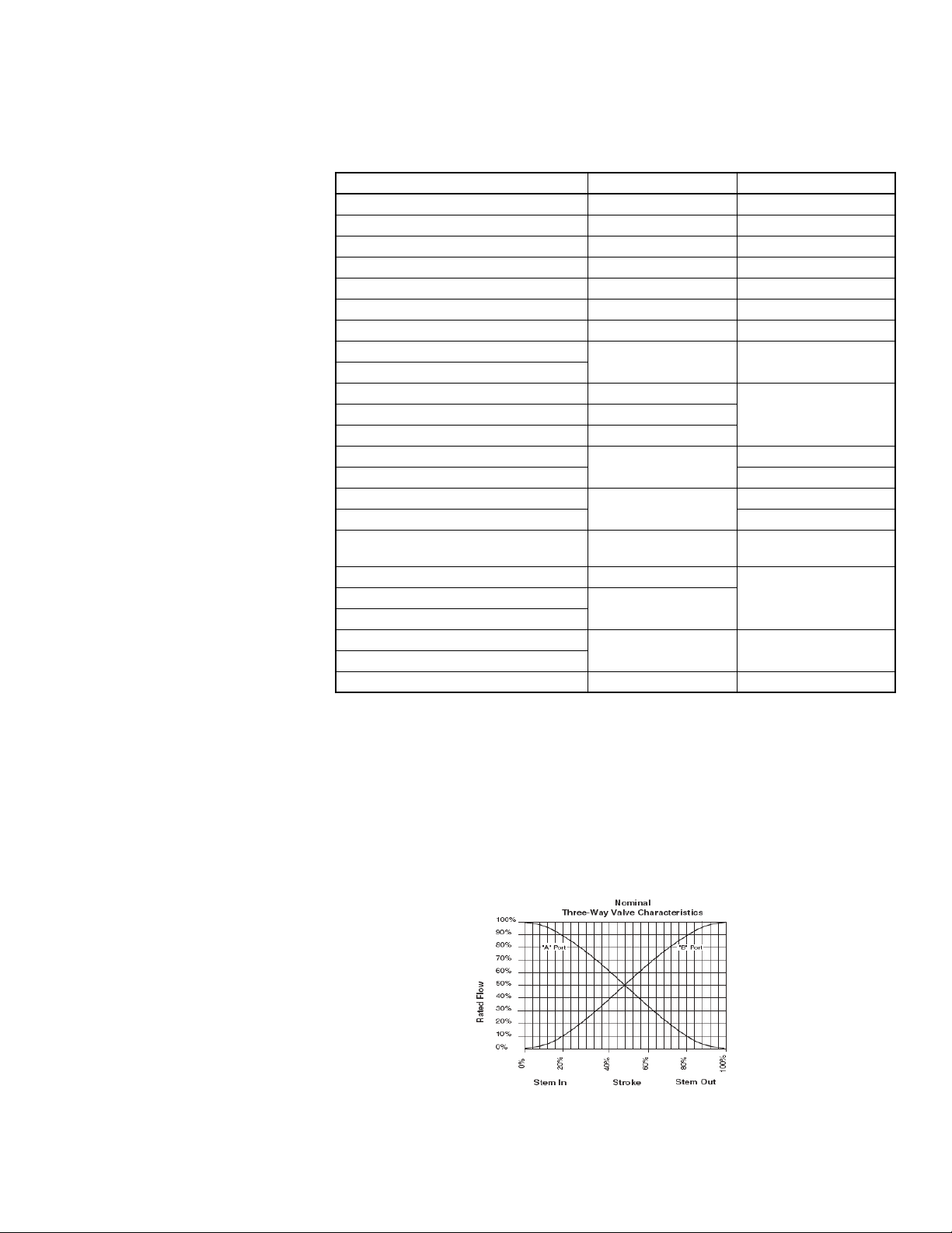
Three-way mixing valves are designed so that the flow from either of the inlet ports to the
outlet is approximately linear, which means the total flow from the outlet is almost constant
over the stroke of the valve stem. See
series valve bodies.
Figure-1 Typical Flow Characteristics.
F-26074-1 © Copyright 2007 TAC All Rights Reserved. 3
Figure-1 for typical flow characteristics of VB-7313
Page 4
Rangeability
Rangeability is the ratio of rated flow to the minimum controllable flow through a valve. For
mixing valves, control begins as soon as plug displacement allows flow. Thus, three-way
valve rangeability normally exceeds 500:1, which is the reciprocal of 0.2% nominal leakage.
Temperature/Pressure Ratings
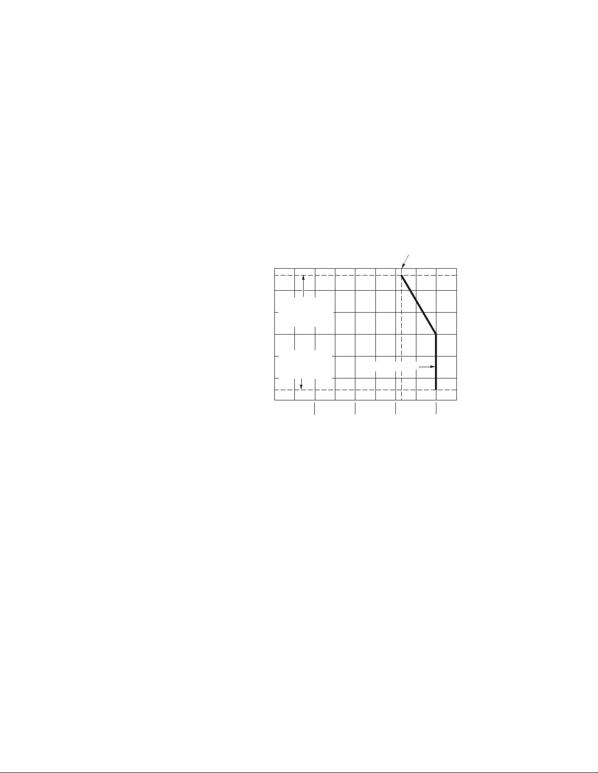
See Figure-2 for temperature and pressure ratings. Consult the appropriate valve linkage
general instruction sheet for the effect of valve body ambient temperatures on specific
actuators. Ratings conform with published values and disclaimer.
VB-7313-0-4-P (Screwed Cast Bronze Body)
Standards: Pressure to ANSI B16.15 Class 250 with 400 psig up to 150°F decreasing to
psig at 281°F
321
Materials: Bronze, ASTM B584
321 psig
(2218 kPa)
300 (149)
250 (121)
200 (93)
150 (65)
Maximum Fluid
Temperature
281¡F (138¡C)
100 (38)
TemperatureÑ¡F (¡C)
50 (10)
Minimum Fluid
Temperature
20¡F (-7¡C)
50
(345)
Figure-2 Temperature and Pressure Ratings
for VB-7313 Series Valve Bodies.
100
(689)
VB-7313-0-4-P
150
(1034)
PressureÑpsig (kPa)
200
(1379)
250
(1724)
300
(2068)
350
(2458)
400
(2758)
4 © Copyright 2007 TAC All Rights Reserved. F-26074-1
Page 5
VALVE SIZING AND SELECTION
Water Two-position
Two-position control valves are normally selected “line size” to keep pressure drop at a
minimum. If it is desirable to reduce the valve below line size, then 10% of “available
pressure” (that is, the pump pressure differential available between supply and return mains
with design flow at the valve location) is normally used to select the valve.
Proportional to Bypass Flow
Proportional valves used to bypass flow (Figure-5) are piped on the outlet side of the load
to throttle the water flow through the load and therefore control heat output of the load.
These valves are usually selected to take a pressure drop equal to at least 50% of the
“available pressure.” As “available pressure” is often difficult to calculate, the normal
procedure is to select the valve using a pressure drop at least equal to the drop in the coil
or other load being controlled (except where small booster pumps are used) with a minimum
recommended pressure drop of 5 psi (34 kPa). When the design temperature drop is less
than 60°F (33°C) for conventional heating systems, higher pressure drops across the valve
are needed for good results (
Table-3 Conventional Heating System.
Design Temperature
Load Drop °F (°C)
60 (33) or More 50% 1 x Load Drop
40 (22) 66% 2 x Load Drop
20 (11) 75% 3 x Load Drop
a
Recommended minimum pressure drop = 5 psi (34 kPa).
Ta bl e -3 ).
Recommended Pressure Drop
(% of Available Pressure)
a
Multiplier on
Load Drop
Secondary Circuits with Small Booster Pumps: 50% of available pressure difference
(equal to the drop through load, or 50% of booster pump head).
Proportional to Blend Water Flows
Proportional valves used to blend two water flows (Figure-6 and Figure-7) control the heat
output by varying the water temperature to the load at constant flow. These valves do not
require high pressure drops for good control results. They can be sized for a pressure drop
of 20% of the “available pressure” or equal to 25% of the pressure drop through the load at
full flow.
Water Capacity
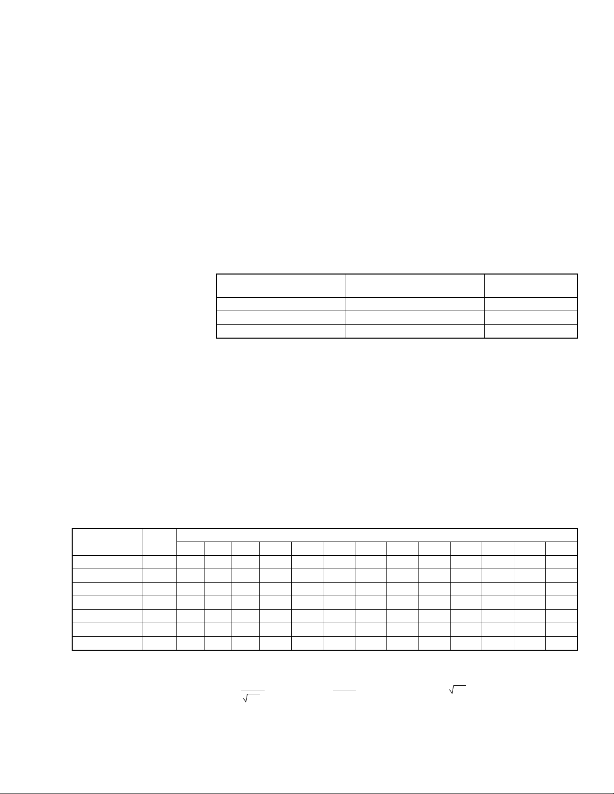
See Ta bl e -4 for water capacity of VB-7313 series valves.
Table-4 Water Capacity in Gallons Per Minute for VB-7313 Series.
Valve Body
Part Number
VB-7313-0-4-2 2.2 2.20 3.11 3.81 4.40 4.92 5.39 5.82 6.22 6.60 6.96 8.52 9.84 13.02
VB-7313-0-4-4 4.4 4.40 6.22 7.6 8.8 9.8 10.8 11. 6 12.4 13.2 13.9 17.0 19.7 26.0
VB-7313-0-4-6 7.5 8.0 11 .3 13.9 16.0 17.9 19.6 21.2 22.6 24.0 25.3 31.0 35.8 47
VB-7313-0-4-8 14 14 20 24 28 31 34 37 40 42 44 54 63 83
VB-7313-0-4-9 20 20 28 35 40 45 49 53 57 60 63 77 89 118
VB-7313-0-4-10 28 28 39 48 56 63 69 74 79 84 88 108 125 166
VB-7313-0-4-11 41 41 58 71 82 92 100 109 116 123 130 159 183 243
C
v
Rating
1 2 3 4 5 6 7 8 9 10 15 20 35
Differential Pressure (ΔP in psi)
Cv Equation
2
GPM
Cv=
ΔP
ΔP=
Where:
Cv= Coefficient of flow
GPM = U.S. gallons per minute (60°F, 15.6°C)
ΔP= Differential pressure in psi (pressure drop)
F-26074-1 © Copyright 2007 TAC All Rights Reserved. 5
GPM
()
C
v
GPM = Cv
ΔP
Page 6
Cavitation Limitations on Valve Pressure Drop
A valve selected with too high a pressure drop can cause erosion of discs and/or wire
drawing of the seat. In addition, cavitation can cause noise, damage to the valve trim (and
possibly the body), and choke the flow through the valve.
Do not exceed the maximum differential pressure (pressure drop) for the valve selected.
The following formula can be used on higher temperature water systems, where cavitation
could be a problem, to estimate the maximum allowable pressure drop across the valve:
Pm = 0.5 (P1 – Pv)
Where:
Pm = Maximum allowable pressure drop (psi)
P1= Absolute inlet pressure (psia)
Pv = Absolute vapor pressure (psia) (refer to Table-5)
Note: Add 14.7 psi to gauge supply pressure to obtain absolute pressure value.
For example, if a valve is controlling 200°F water at an inlet pressure of 18 psig, the
maximum pressure drop allowable would be:
Pm = 0.5 [(18 + 14.7) – 11.53] = 10.6 psi
(Vapor pressure of 200°F water is 11.53 psia.)
If the pressure drop for this valve is less than 10.6 psi, cavitation should not be a problem.
Systems where cavitation is shown to be a problem can sometimes be redesigned to provide
lower inlet velocities. Valves having harder seat materials should be furnished if inlet
velocities cannot be lowered.
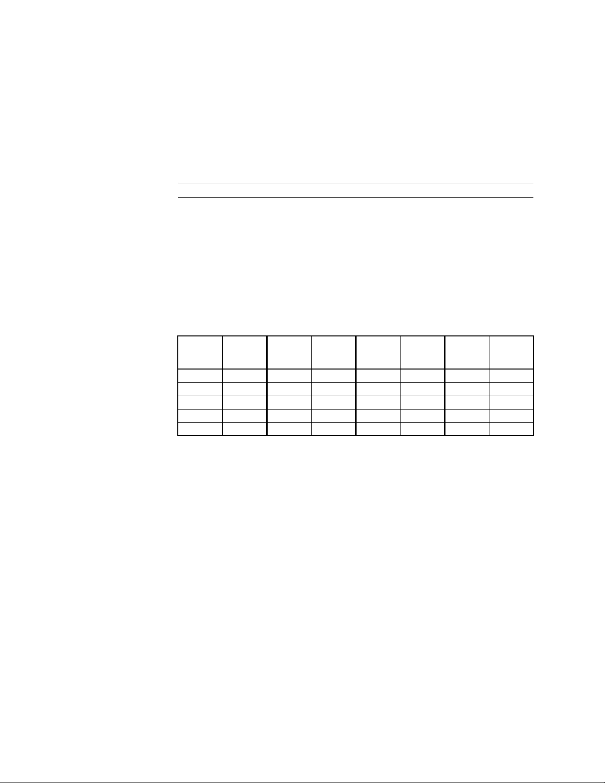
Table-5 Vapor Pressure of Water Table.
Additional Valve Sizing Information
Water
Tem p.
(°F)
40 0.12 90 0.70 140 2.89 190 9.34
50 0.18 100 0.95 150 3.72 200 11.53
60 0.26 110 1.28 160 4.74 210 14.12
70 0.36 120 1.69 170 5.99 220 17.19
80 0.51 130 2.22 180 7.51 230 20.78
Vap or
Pressure
(psia)
Water
Tem p.
(°F)
Vap or
Pressure
(psia)
Water
Tem p.
(°F)
Vapor
Pressure
(psia)
Water
Tem p.
(°F)
For additional valve sizing information, see:
• CA-28 Control Valve Sizing, F-13755
• Valve Selection Chart Water, F-11080
Vapor
Pressure
(psia)
6 © Copyright 2007 TAC All Rights Reserved. F-26074-1
Page 7
INSTALLATION
Inspection Inspect the package for damage. If damaged, notify the appropriate carrier immediately.
If undamaged, open the package and inspect the device for obvious damage. Return
damaged products.
Requirements • Tools (not provided): Pipe wrenches
• Training: Installer must be a qualified, experienced technician
• Appropriate accessories
Caution:
• Install the valve with the flow in the direction of the flow arrows (“A” and “B” ports are
inlets and “AB” port is the outlet).
• Do not exceed the ratings of the device.
• Avoid locations where excessive moisture, corrosive fumes, or vibration are present.
Mounting 1. The valve should be mounted in a weather-protected area in a location that is within the
ambient limits of the actuator. When selecting a location, allow sufficient room for valve
linkage, actuator, and other accessories and for service of the product.
2. The preferred mounting position for the valve is with the valve stem vertical above the valve body. Avoid mounting the valve so that the valve stem is below horizontal.
3. The valves must be piped with two inlets (“A” and “B” ports) and one outlet (“AB” port).
Screwed Valve Bodies
The VB-7313-0-4-P series screwed valve bodies conform to American Standard Taper Pipe
Threads (NPT).
1. Apply pipe dope sparingly to all but the last two threads of a properly threaded, reamed,
and cleaned pipe. Make sure that pipe chips, scale, etc. do not get into the pipe since this
material may lodge in the valve seat and prevent proper closing and opening of the valve.
2. Start the joint by hand screwing the pipe into the valve. If the thread engagement feels “right,” turn the pipe by hand as far as it will go.
3. Use a pipe wrench to fully tighten the valve to the pipe. Do not over tighten or strip
threads. SeeTa bl e -6 and Figure-3 for the normal engagement length of the threads.
Figure-4 shows a means of tightening the pipe so that the valve is not twisted or
crushed.
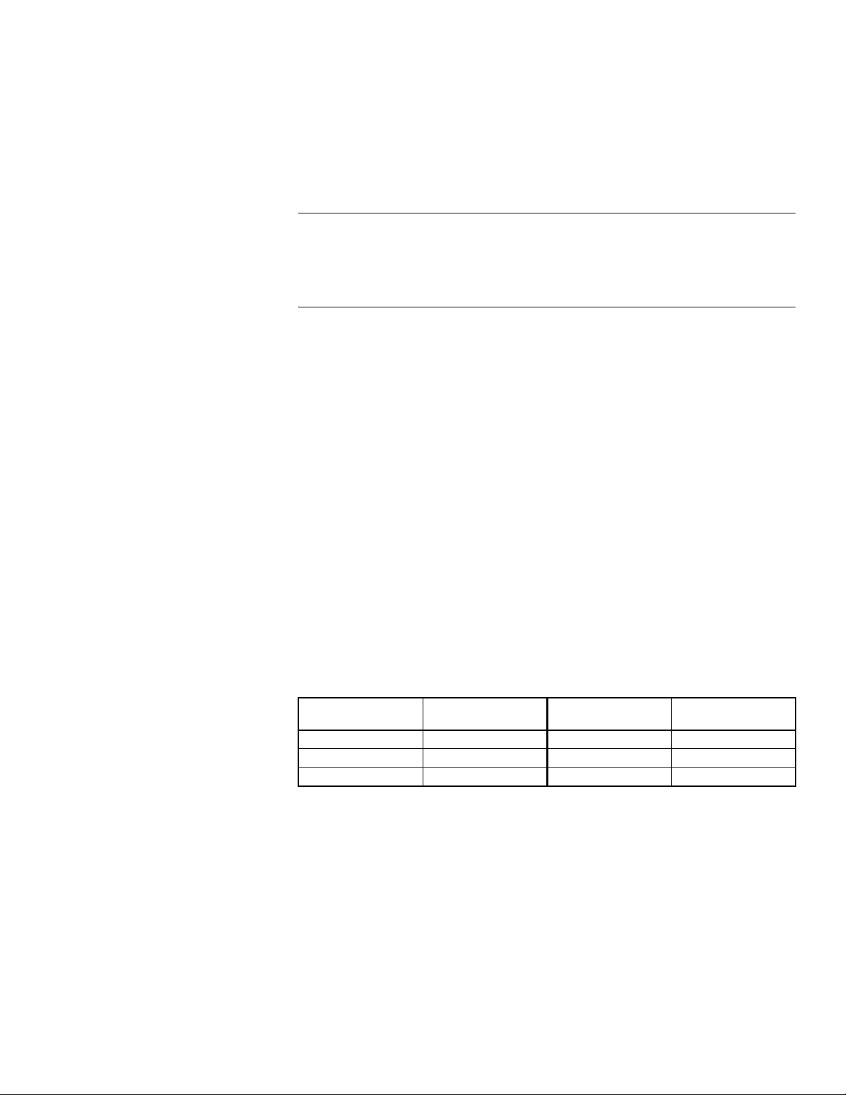
Table-6 Normal Thread Engagement Between Male Pipe Thread and Valve Body.
Valve Size Inches
(NPT)
1/2" 1/2" 1-1/4" 11/16"
3/4" 9/16" 1-1/2" 11/16"
1" 11/16" 2" 3/4"
F-26074-1 © Copyright 2007 TAC All Rights Reserved. 7
Normal Engagement
Valve Size Inches
(NPT)
Normal Engagement
Page 8
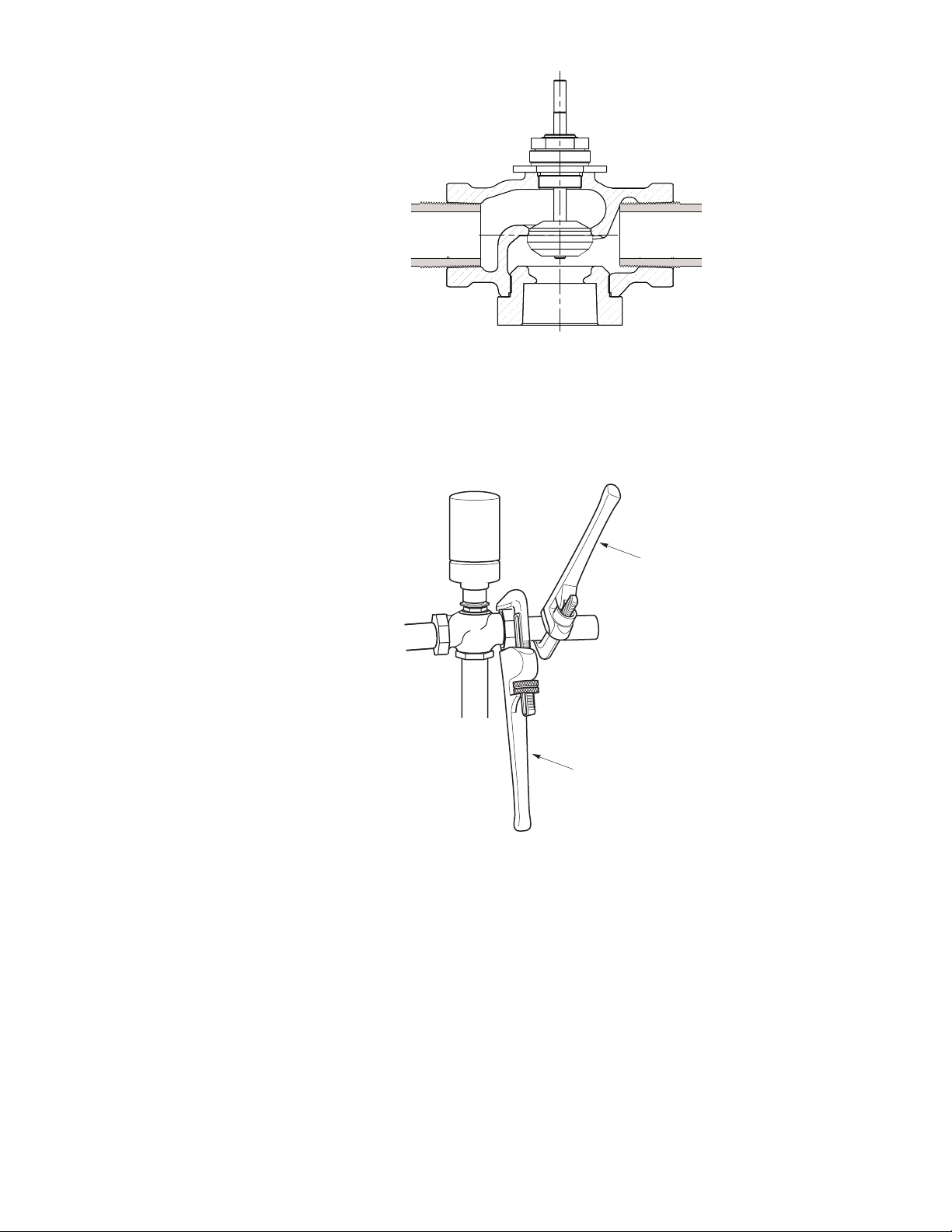
Right Wrong
Pipe threads too long
Pipe interferes with seat
Figure-3 Normal Thread Engagement.
Valve
Assembly
Use pipe wrench to
prevent valve from turning.
Figure-4 Installation of Screwed End Valves.
Tighten pipe using
this pipe wrench.
8 © Copyright 2007 TAC All Rights Reserved. F-26074-1
Page 9
TYPICAL PIPING
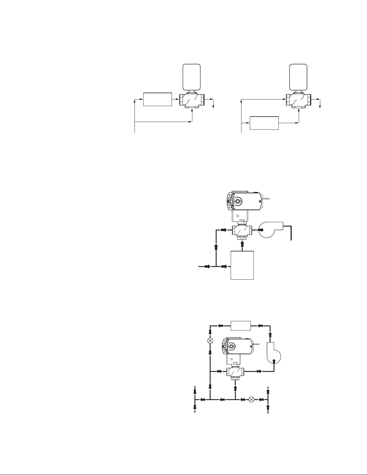
All piping must comply with local codes and ordinances. Refer to Figure-5 through
Figure-7 for typical piping.
Valve
Coil
A
A
B
B
Return
Bypass
Supply Supply
Stem down flow through coil.
Stem up flow through coil bypass.
Stem up flow through coil.
Stem down flow through coil bypass.
Figure-5 Typical Piping for Control of Heating or Cooling Coil.
Val ve
Assembly
A
A
A
A
B
B
B
B
Bypass
Supply
Bypass
Coil
System
Pump
Valve
A
A
B
B
Return
Return
Boiler
Typical Boiler Hot Water Reset
Figure-6 Typical Boiler Hot Water Reset.
Coil
Balancing
Cock
Val ve
Assembly
A
A
A
A
B
B
B
From
Other
Zones
Return
Typical Primary-Secondary Piping
B
Balancing
Cock
To Other
Zones
Supply
Figure-7 Typical Primary-Secondary Piping.
F-26074-1 © Copyright 2007 TAC All Rights Reserved. 9
Page 10
CHECKOUT
MAINTENANCE
1. Make sure the valve stem operates smoothly before installing the valve linkage and the actuator.
2. If the stem does not operate smoothly, it may indicate that the valve was twisted or crushed during installation or that the stem was bent by rough handling. These conditions may require that the valve be replaced.
3. After the piping is under pressure, check the valve body and the connections for leaks.
4. After the valve linkage and the actuator are installed, check their operation.
a. Drive the actuator and run the valve to the stem down position. Make sure the
linkage and valve stem move freely. At the stem down position, the valve should
shut off the “B” port.
b. Drive the actuator and valve to the stem up position. Again, the valve stem and
linkage should operate smoothly. At the stem up position, the valve should shut off
the “A” port.
Regular maintenance of the total system is recommended to assure sustained performance.
See Table-7 for maintenance kit part numbers.
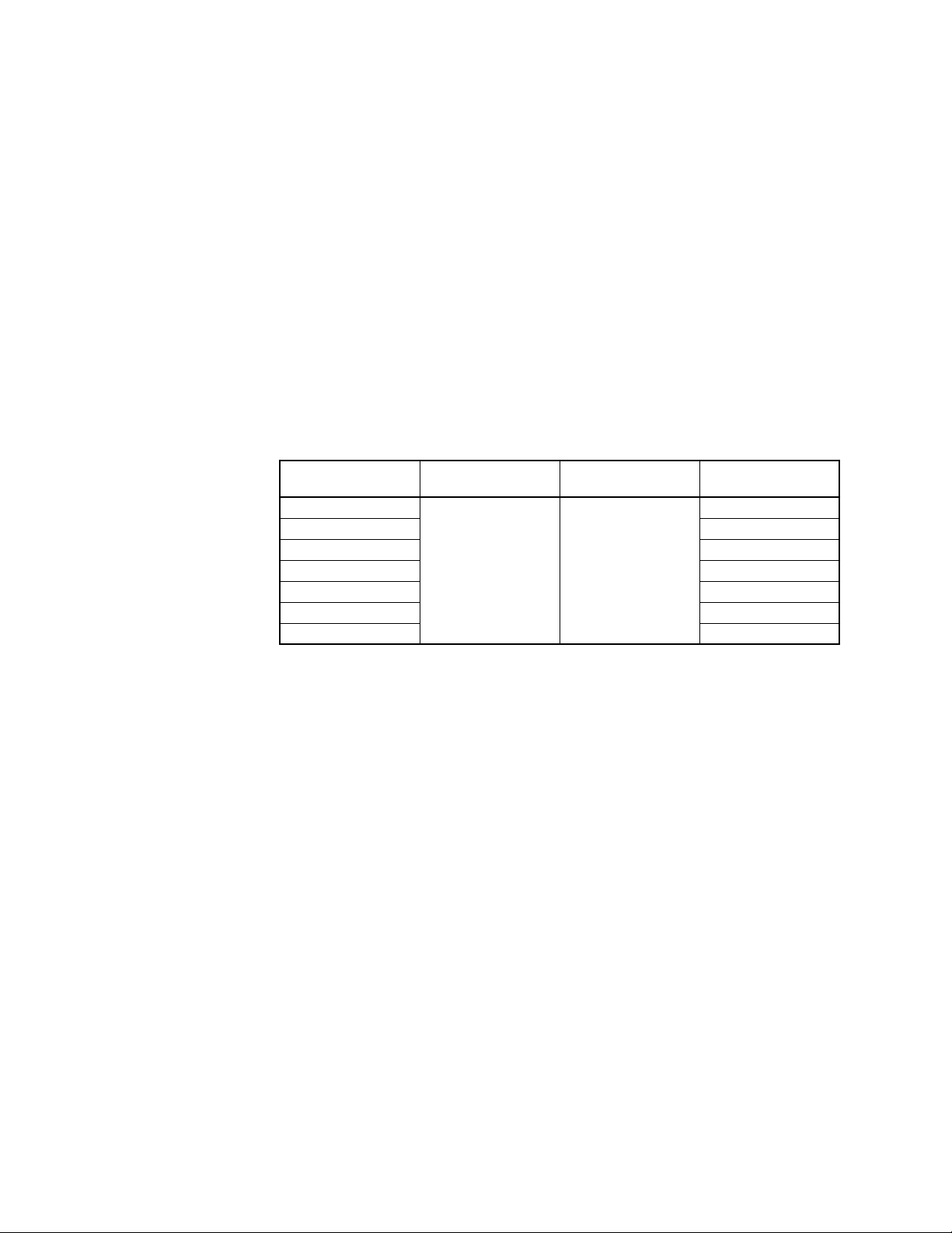
Table-7 Maintenance Kits for VB-7313 Valves.
Water System Maintenance
Valve Body
Part Number
VB-7313-0-4-2
VB-7313-0-4-4 RYB-731-4
VB-7313-0-4-6 RYB-731-6
VB-7313-0-4-8 RYB-731-8
VB-7313-0-4-9 RYB-731-9
VB-7313-0-4-10 RYB-731-10
VB-7313-0-4-11 RYB-731-11
a
Kit includes replacement packing and stem & plug assembly.
Replacement
Packing Assembly
YBA-622-2 TOOL-20-1
Packing Wrench Valve Repair Kit
a
RYB-731-2
All heating and cooling systems are susceptible to valve and system problems caused by
improper water treatment and system storage procedures. These guidelines are provided to
help avoid valve and water system problems resulting from improperly treated water or
storage procedures in cooling and hot water systems, and to obtain maximum life from TAC
valves.
Durability of valve stems and packings is dependent on maintaining non-damaging water
conditions. Inadequate water treatment or filtration, not in accordance with chemical
supplier/ASHRAE handbook recommendations, can result in corrosion, scale, and abrasive
particle formation. Scale and particulates can result in stem and packing scratches and can
adversely affect packing life and other parts of the hydronic system.
To maintain non-damaging conditions, follow these guidelines:
• Clean the system prior to start up. Use a nitrite or molybdate-based treatment program.
• Use filtration equipment where needed.
• Properly store off-line systems and monitor water treatment results using corrosion test
coupons.
• Follow the advice of a water treatment professional.
• Consult EN-205, Water System Guidelines Engineering Information, F-26080, for
further details.
10 © Copyright 2007 TAC All Rights Reserved. F-26074-1
Page 11
DIMENSIONAL DATA
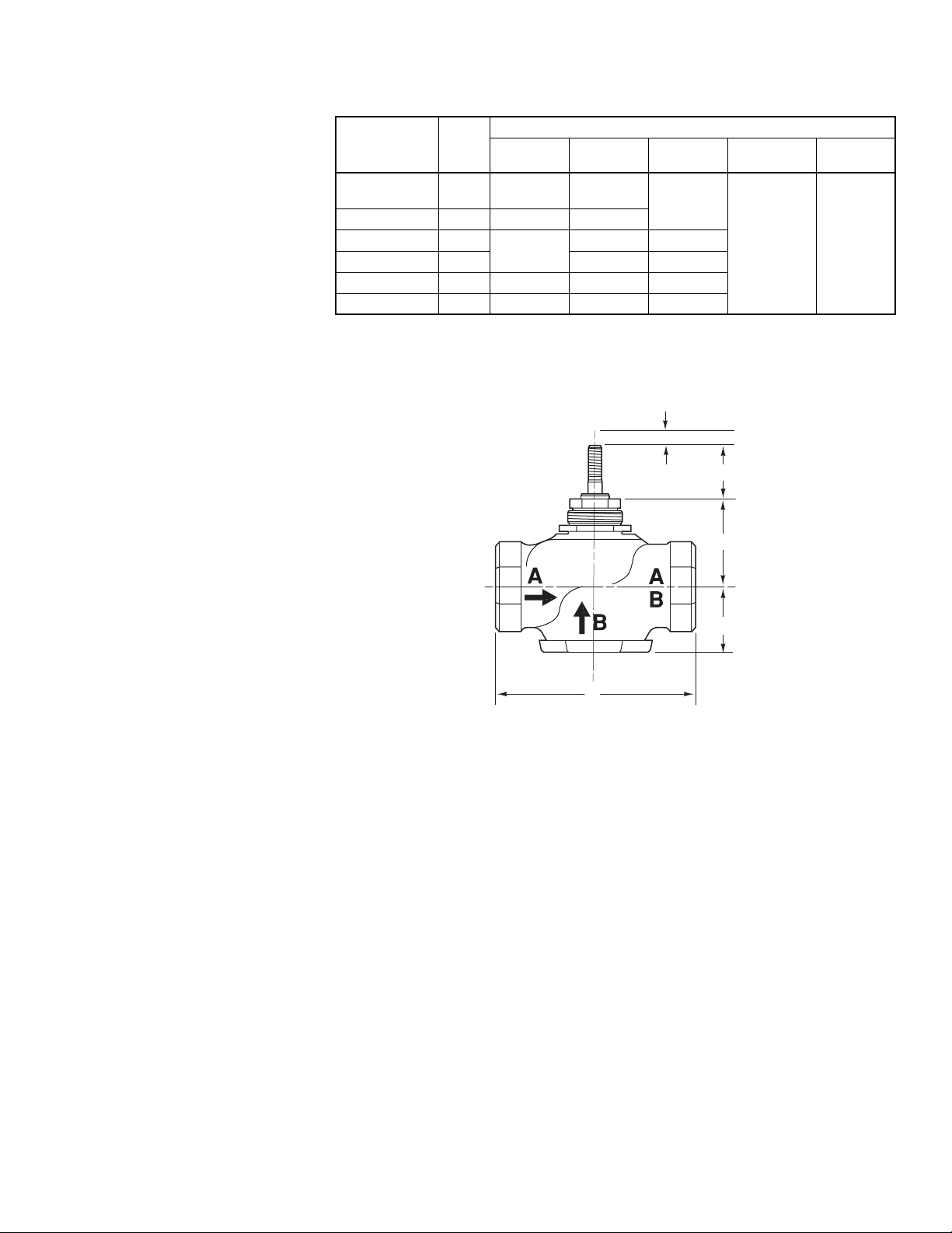
Table-8 Dimensions for VB-7313 Series Valves (Figure-8).
Part
Number
VB-7313-0-4-2
VB-7313-0-4-4
VB-7313-0-4-6 3/4" 3-5/8 (92) 1-11/16 (43)
VB-7313-0-4-8 1"
VB-7313-0-4-9 1-1/4" 1-13/16 (46) 2 (51)
VB-7313-0-4-10 1-1/2" 5-3/8 (137) 1-5/8 (41) 1-1/8 (29)
VB-7313-0-4-11 2" 6-1/8 (156) 1-7/8 (48) 1-3/16 (30)
Valve
Size
1/2" 3 (76) 1-3/8 (35)
A B C
4-5/8 (117)
Dimensions in Inches (mm)
1-11/16 (43)
1-9/16 (40) 1-3/4 (45)
E
D
(Stem Down)E(Stroke)
3/4 (19) 7/16 (11)
D
C
B
A
Figure-8 Typical of VB-7313-0-4-P Valve Bodies.
F-26074-1 © Copyright 2007 TAC All Rights Reserved. 11
Page 12

Copyright 2007, TAC
All brand names, trademarks and registered
trademarks are the property of their respective
owners. Information contained within this
document is subject to change without notice.
F-26074-2
TAC
1354 Clifford Avenue
P.O. Box 2940
Loves Park, IL 61132-2940
www.tac.com
 Loading...