

Page 1
TAC
1354 Clifford Avenue
P. O. Box 2940
Loves Park, IL 61132-2940
www.tac.com
Application
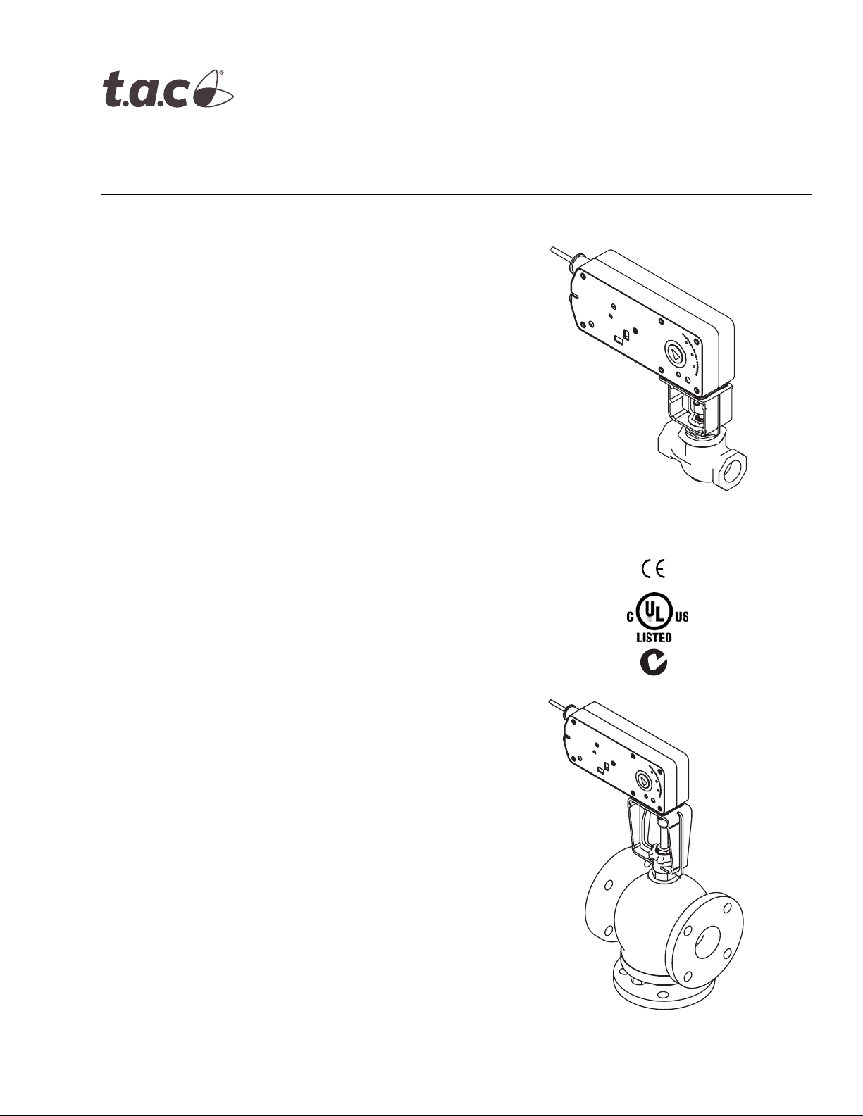
TAC DuraDrive Linear Actuators are designed to
mount directly onto two-way or three-way valves. They
provide linear travel to economically operate 1-1/4" to
2" VB-7xxx, 2-1/2” to 5" VB-8xxx, 2-1/2" to 4" VB-931x,
and discontinued 1-1/2” to 4” VB-9xxx valves in hot
water, chilled water, and steam applications up to
366°F (186°C) fluid temperature.
The linear spring return actuators provide either two position, floating or proportional modulation control (depending on model selection) of valves in HVAC systems.
MAx1-720x Two Position Series
MFx1-7203 Floating Series
MSx1-7203 Proportional Series
TAC DuraDrive™ Linear Series
Spring Return Actuator
General Instructions
Features
• Two position models controlled by SPST controller
• Floating models controlled by SPDT floating
controllers
• Proportional models controlled by 2-10 Vdc, or 4-20
mAdc with the addition of a 500 ohm resistor.
Control function direct/reverse action is switch
selectable
• 220 lb force (979 newton) with 1/2” (13 mm) or
1" (25 mm) nominal linear stroke
• Automatically sets control signal input span to match
valve travel
• 24 Vac, 120 Vac, and 230 Vac models
• Rugged die-cast enclosures rated for NEMA 2, UL
Type 2/IP54
• Overload protection throughout stroke
• Compact size for application flexibility
• Manual override to allow positioning of valve and
preload
Mx51-720x
• Integral linkage for direct mount to valves
• Five year warranty
Mx61-720x
Printed in U.S.A. 11-06 © Copyright 2006 TAC All Rights Reserved. F-27120-4
Page 2

Applicable Literature
• TAC DuraDrive Linear Series Spring Return Actuator Submittal Sheet, F-27165
• Two-Way and Three-Way Globe Valve Assemblies with TAC DuraDrive Linear Series Spring Return Actuators Submittal Sheet, F-27167
• EN-205 Water System Guidelines, F-26080
• Vx-7xxx, Vx-9xxx Series Linked Globe Valves with TAC DuraDrive Linear Series Actuators Selection Guide, F-27252
• Vx-8xxx Valve Selection Guide, F-27199
• AM-731, AM-732, AM-733, AM-734, Kit General Instructions, F-27203
• VB-7213 Series 1/2" to 2" Screwed NPT, Stem Up Open, Two-Way Valves, General Instructions, F-26075
• VB-7214 Series 1/2" to 2" Union Sweat, Solder Joint Stem Up Open, Two-Way Valves, General Instructions, F-25675
• VB-7215 Series 15 mm to 50 mm Screwed Rp, Stem Up Open, Two-Way Valves, General Instructions, F-26077
• VB-7223 Series 1/2" to 2" Screwed NPT, Stem Up Closed, Two-Way Valves, General Instructions, F-26073
• VB-7224 Series 1/2" to 2" Union Sweat, Solder Joint Stem Up Closed, Two-Way Valves, General Instructions, F-24387
• VB-7225 Series 15 mm to 50 mm Screwed Rp, Stem Up Closed, Two-Way Valves, General Instructions, F-26079
• VB-7253 Series 1/2" to 2" Screwed NPT, Stainless Steel Trim with Teflon Disc, Stem Up Open, Two-Way Valves, General Instructions,
F-24388
• VB-7263 Series 1/2" to 2" Screwed NPT, Stainless Steel Trim with Teflon Disc, Stem Up Closed, Two-Way Valves, General Instructions,
F-24389
• VB-7273 Series 1/2" to 2" Screwed NPT, Stainless Steel Trim, Stem Up Open, Two-Way Valves, General Instructions, F-24390
• VB-7283 Series 1/2" to 2" Screwed NPT, Stainless Steel Trim, Stem Up Closed, Two-Way Valves, General Instructions, F-24391
• VB-7313 Series 1/2" to 2" S crewed NPT, Three-Way Mixing Valves, General Instructions, F-26074
• VB-7314 Series 1/2" to 2" Union Sweat, Solder Joint, Three-Way Mixing Valves, General Instructions, F-24394
• VB-7315 Series 15 mm to 50 mm Screwed Rp, Three-Way Mixing Valves, General Instructions, F-26078
• VB-7323 Series 1/2” to 2” Screwed NPT Three-way Diverting Valves, General Instruction, F-26076
• VB-8213 Series 2-1/2” to 6" Flanged, Stem Up Open, Two-Way Valves, General Instructions, F-27193
• VB-8223 Series 2-1/2” to 6" Flanged, Stem Up Closed Two-Way Valves, General Instructions, F-27194
• VB-8303 Series 2-1/2” to 6" Flanged, Three-Way Diverting/Mixing Valves, General Instructions, F-27197
• VB-9213 Series, 2-1/2” and 3” Screwed NPT, 2-1/2” to 6” 125 Lb. Flanged, Stem Down to Close Two-Way Valves, General Instructions,
F-24382
• VB-9215 Series, 65 mm and 80 mm Screwed R
• VB-9223 Series, 2-1/2” and 3” Screwed NPT, 2-1/2” to 6” 125 Lb. Flanged, Stem Up to Close Two-Way Valves, General Instructions,
F-24386
• VB-9225 Series, 65 mm and 80 mm Screwed R
• VB-9313 Series, 2-1/2” and 3” Screwed NPT, 2-1/2” to 6” 125 Lb. Flanged, Three-Way Mixing Valves, General Instructions, F-24393
• VB-9315 Series, 65 mm and 80 mm Screwed R
, Stem Down to Close Two-Way Valves, General Instructions, F-25672
p
, Stem Up to Close Two-Way Valves, General Instructions, F-25673
p
, Three-Way Mixing Valves, General Instructions, F-25674
p
2 © Copyright 2006 TAC All Rights Reserved. F-27120-4
Page 3

SPECIFICATIONS
a
Actuator Inputs
Control Signal: MAx1-720x—On-off spring return, SPST control contacts or Triacs
(500mA rated). MFx1-7203—Floating point, SPDT control contacts or Triacs (500 mA rated)
24 Vac. MSx1-7203—Proportional, 2 to 10 Vdc or 4 to 20 mAdc with 500 Ω resistor.
Power Input: MAx1-720x—24 Vac ± 20%, 22 to 30 Vdc, 120 Vac ± 10%, 230 Vac ± 10%,
50/60 Hz. All 24 Vac circuits are Class 2. All circuits 30 Vac and above are Class 1.
MFx1-7203, MSx1-7203— 24 Vac ± 20%, Class 2, 22 to 30 Vdc. Connections: 3 ft (91 cm) appliance cables, 1/2 inch (13 mm) conduit connectors. For M20
Metric conduit, use AM-756 adaptor.
Actuator Outputs
Electrical:
Position Feedback Voltage (proportional only):
MSx1-7203—2 to 10 Vdc (max. 0.5 mA) output signal for position feedback or to
operate up to four additional slave actuators.
Mechanical:
Motor Type: Brushless DC.
Linear Stroke (Nominal): Mx51-720x—1/2" (13 mm). Mx61-720x—1” (25 mm).
Approx. Stroke Timing, 100 seconds for 1/2" stroke. 190 seconds for 1” stroke. Manual Override, Allows positioning of valve and preload using manual crank. Right/Left Switch, Permits reverse acting/direct acting linear motion (MSx1 only).
Environment:
Ambient Temperature Limits,
Shipping & Storage, -40 to 160 °F (-40 to 71 °C).
Operating, 0 to 140 °F (-18 to 60 °C).
Temperature Restrictions,
Actuator
Mx51-720x
Mx61-720x 140 °F (60 °C)@ 300 °F (149 °C) 2-1/2" to 4" VB-931x
Mx61-720x 140 °F (60 °C)@ 281 °F (138 °C)
Discontinued
Max. Allowable Ambient
@ Max. Fluid Temperatures
Valve Body
140 °F (60 °C)@ 281 °F (138 °C) VB-721x, 722x
120 °F (49 °C)@ 300 °F (149 °C) VB-73xx
100 °F (38 °C)@ 340 °F (171 °C) VB-725x, 726x
90 °F (32 °C)@ 366 °F (186 °C) VB-727x, 728x
2-1/2” to 5” VB-8xx3,
2-1/2" to 4" VB-92xx
a
Humidity: 15 to 95% RH, non-condensing. Location:
NEMA1. NEMA 2, UL Type 2 (IEC IP54) with customer supplied watertight conduit
connectors.
Agency Listings
UL 873: Underwriters Laboratories (File #E9429 Category Temperature-Indicating and
Regulating Equipment).
CUL: UL Listed for use in Canada by Underwriters Laboratories. Canadian Standards
C22.2 No. 24-93.
European Community: EMC Directive (89/336/EEC). Low Voltage Directive (72/23/EEC) Australia: This product meets requirements to bear the C-Tick Mark according to the terms
specified by the Communications Authority under the Radiocommunications Act 1992.
The specifications conform to acceptable industry standards. For applications at conditions
beyond these specifications, consult your local TAC representative office. TAC shall not be
liable for damages resulting from misapplication or misuse of its products.
F-27120-4 © Copyright 2006 TAC All Rights Reserved. 3
Page 4

Table-1 Specifications.
Approximate
Stroke Timing in
Seconds @ 70°F
(21°C)
Powered
Spring
Return
Part
Number
Control
Action
Voltage
Actuator Power Input
Running Holding
50 Hz 60 Hz
VA W VA W W
Amps
DC
50/60
Hz
Linear
Stroke
Inches
24Vac
MA51-7203
±20%
9.8 7.5 9.7 7.5 .29 2.8
22-30 Vdc
MA51-7200
MA51-7201
MA61-7203
2
Position
120 Vac
±10%
230 Vac
±10%
24 Vac
±20%
11.7 8.8 10.0 8.4 N/A 3.6/5.0
15.5 9.5 10.6 8.5 N/A 4.6/3.3
9.8 7.5 9.7 7.5 .29 2.8
5/8 <100 <35
22-30 Vdc
MA61-7200
MA61-7201
120 Vac
±10%
230 Vac
±10%
11.7 8.8 10.0 8.4 N/A 3.6/5.0
15.5 9.5 10.6 8.5 N/A 4.6/3.3
1-1/16 <190 <40
24 Vac
MF51-7203
Floating
MF61-7203
±20%
22-30 Vdc
24 Vac
±20%
9.8 7.7 9.7 7.7 .30 3.3 5/8 <100 <35 1-1/4" to 2"
9.8 7.7 9.7 7.7 .30 3.3 1-1/16 <190 <40
22-30 Vdc
24 Vac
MS51-7203
Proportional
MS61-7203
±20%
22-30 Vdc
24 Vac
±20%
9.8 7.4 9.7 7.4 .28 2.9 5/8 <100 <35 1-1/4" to 2"
9.8 7.4 9.7 7.4 .28 2.9 1-1/16 <190 <40
22-30 Vdc
a
Timing was measured with no load applied to the actuator.
b
Current VB-7xxx series valves and discontinued 1-1/4” VB-9xxx series valves.
c
Current VB-931x Series valves (2-1/2" to 4"), current VB-8xx3 (2-1/2” to 5”) Series valves, and discontinued VB-9xxx (1-1/2" to 4") Series valves.
a
Output Force
Rating
lb. (Newton)
Min.
220
(979)
Max.
Stall
495
(2202)
Valve
Size
1-1/4" to 2"
2-1/2" to 4"
c
or 5”
2-1/2" to 4"
c
or 5”
2-1/2" to 4"
c
or 5”
b
b
b
ACCESSORIES
AM-763 1/8” Hex crank for manual override
AM-756 Metric conduit adapter M20 x 1.5 to 1/2” NPT
AM-731 Mounting kit - Mx51-720x (stem extension, lock washer, jam nut, and connecting
pin; included with actuator)
AM-732 Mounting kit - Mx61-720x (stem extension, lock washer, jam nut, and connecting
pin; included with actuator)
AM-733 Retrofit kit - discontinued VB-9xxx 1-1/2 to 2" valves after 9404 date code
AM-734 Retrofit kit - discontinued VB-9xxx -1/2 to 2" valves prior to 9404 date code
MSx1-7203
AM-703 Input rescaling module, adjust signals to 2-10 Vac, zero and span adjust
AM-704 Interface, pulse width modulation (PWM)
AM-705 Positioner (NE MA 4 housing)
AM-706 Min and/or manual positioner for flush panel mount
AM-708 500 Ω resistor for 4 to 20 mAdc control signal
4 © Copyright 2006 TAC All Rights Reserved. F-27120-4
Page 5
Close-Off Pressure and Maximum Operating Pressure Differential
For all valve assemblies, be sure to check that the anticipated maximum pressure drop
across the valve in the closed position will not exceed the close-off pressure rating and that
the pressure differential across the valve will not exceed the maximum operating pressure
differential rating. For VB-7xxx and VB-9xxx valve applications, consult the Vx-7xxx &
Vx-9xxx Selection Guide, F-27252. For VB-8xx3 valve applications, consult the Vx-8xxx
Selection Guide, F-27199.
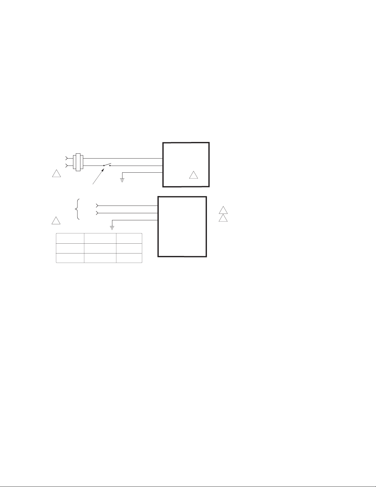
TYPICAL TWO POSITION CONTROL (wiring diagrams)
Figure-1 illustrates typical wiring diagrams for spring return MAx1-720x Series spring return
two-position actuators. See Table-1 for model selection.
24 Vac Transformer
or 22-30 Vdc
Line
Volts
1
SPST Control Contact
Blk
Red
Com
Hot (+DC)
Grn/Yel
MA51-7203
MA61-7203
2
120 Vac or
230 Vac
1
Voltage Wire 1 Wire 2
120 Vac White Black
230 Vac Blue Brown
L1 N
L2 H
Wire No. 1
Wire No. 2
Com
Hot
Grn/Yel
MA51-7200
MA51-7201
MA61-7200
MA61-7201
1 Provide overload protection and disconnect as required.
2 Actuators mounted on separate valves may be wired in
parallel. Power supply black wires are connected to the
transformer common and power supply red wires are
connected to the hot lead. Power consumption must be
observed.
Figure-1 Typical Wiring Diagrams for Two Position Actuators.
F-27120-4 © Copyright 2006 TAC All Rights Reserved. 5
Page 6
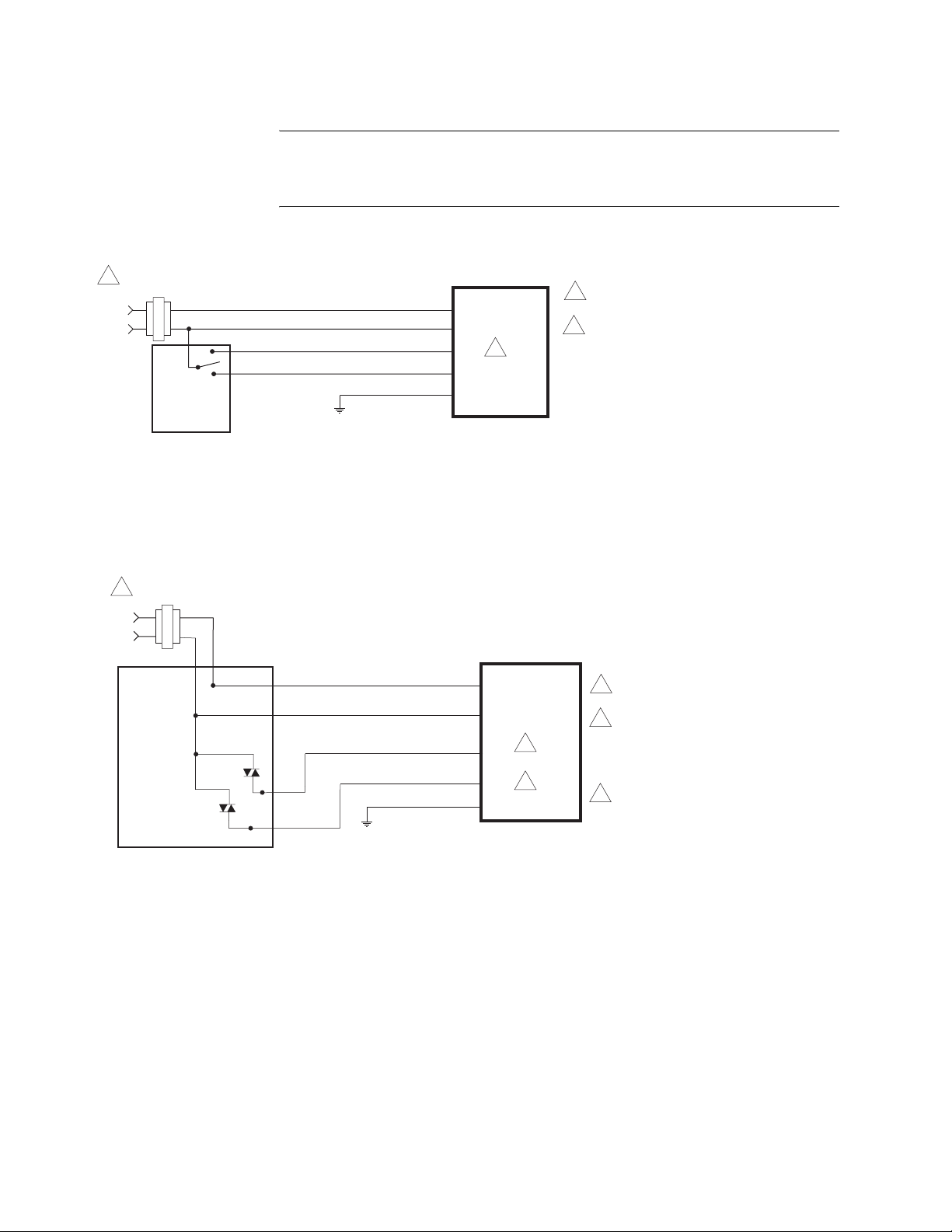
TYPICAL FLOATING CONTROL (wiring diagrams)
Figure-2 through Figure-5 illustrate typical wiring diagrams for MFx1-7203 Series spring
return floating actuators. See Table-1 for model selection.
24 Vac Transformer
1
or 22-30 Vdc
Line
Volts
Controller
24 Vac Transformer
1
or 22-30 Vdc
Line
Volts
Typical
Floating
Caution:
This product contains a half-wave rectifier power supply and must not be
powered off transformers used to power other devices utilizing non-isolated full-wave
rectifier power supplies. Refer to
Common Transformer, F-26363
Black
Red
Blue
Yellow/Black
Common
Hot (+DC)
Extend
Retract
Green/Yellow
EN-206, Guidelines for Power Multiple Devices from a
for detailed information.
MF51-7203
MF61-7203
2
1 Provide overload protection and
disconnect as required.
2 Actuators may be wired in parallel.
All actuator black wires are
connected to the transformer
common and all red wires are
connected to the hot lead. Power
consumption must be observed.
Figure-2 Floating Point Control.
Hot
Controller
Common
Black
Red
Blue
Yellow/Black
Green/Yellow
Figure-3 Triac Source.
Common
Hot (+DC)
Extend
Retract
MF51-7203
MF61-7203
2
3
1 Provide overload protection
and disconnect as required.
2 If the controller uses a full-
wave power supply and does
not provide isolated outputs, a
separate transformer is
required.
3
Actuators may be wired in parallel.
All actuator black wires are
connected to the transformer
common and all red wires are
connected to the hot lead. Power
consumption must be observed.
6 © Copyright 2006 TAC All Rights Reserved. F-27120-4
Page 7
24 Vac Transformer
1
Line
Volts
or 22-30 Vdc
Common
Hot
Controller
Black
Red
Blue
Yellow/Black
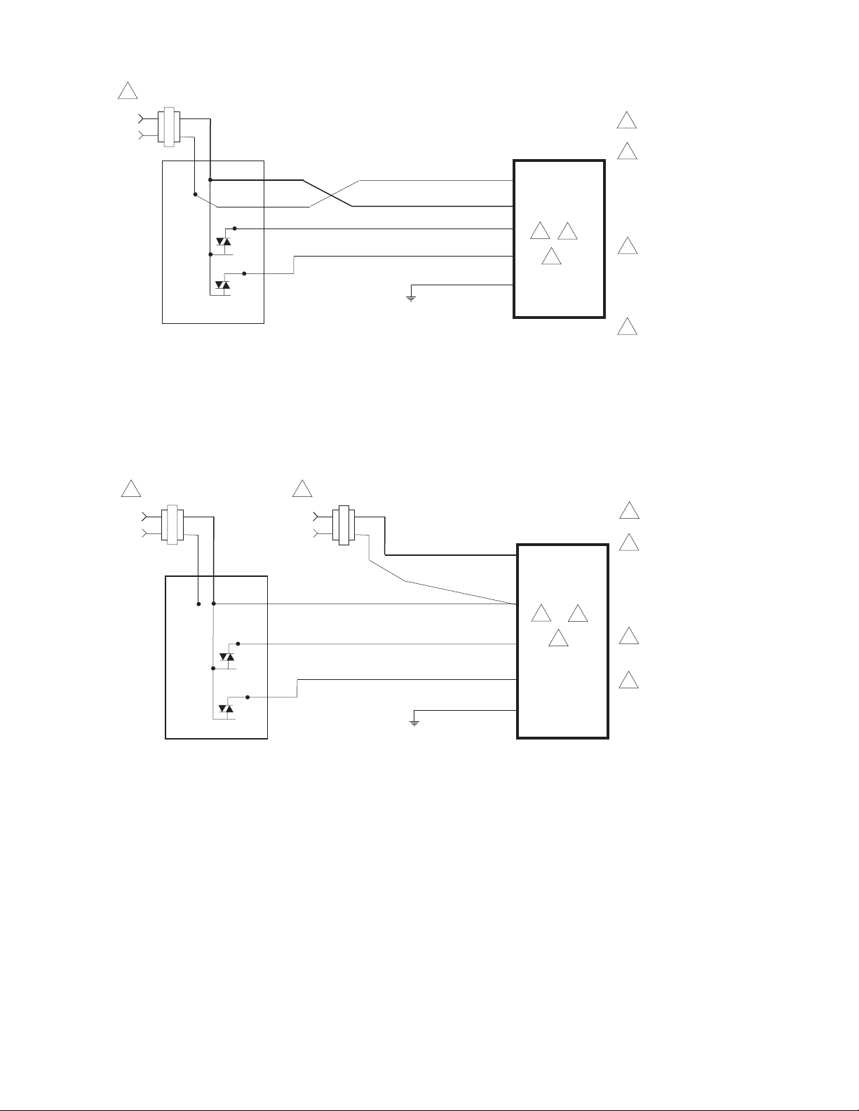
Figure-4 Triac Sink.
Common
Hot (+DC)
Extend
Retract
Green/Yellow
MF51-7203
MF61-7203
2
3
4
1 Provide overload protection and
disconnect as required.
2 Actuators may be wired in
parallel. All actuator black wires
are connected to the
transformer common and all
red wires are connected to the
hot lead. Power consumption
must be observed.
3 The Common connection from
the actuator must be connected
to the Hot connection of the
controller. The actuator Hot
must be connected to the
controller Common.
4 If the controller uses a full-
wave power supply and does
not provide isolated outputs, a
separate transformer is
required.
24 Vac Transformer
1
or 22-30 Vdc
Line
Volts
Hot
Controller
Common
24 Vac Transformer
1
or 22-30 Vdc
Line
Volts
Black
Red
Blue Extend
Yellow/Black
Common
Hot (+DC)
Retract
Green/Yellow
Figure-5 Triac Sink With Separate Transformers.
MF51-7203
MF61-7203
2
3
4
1 Provide overload protection
and disconnect as required.
2 Actuators may be wired in
parallel. All actuator black
wires are connected to the
transformer common and all
red wires are connected to the
hot lead. Power consumption
must be observed.
3 The actuator Hot must be
connected to the controller
Common.
4 If the controller uses a full-
wave power supply and does
not provide isolated outputs, a
separate transformer is
required.
F-27120-4 © Copyright 2006 TAC All Rights Reserved. 7
Page 8
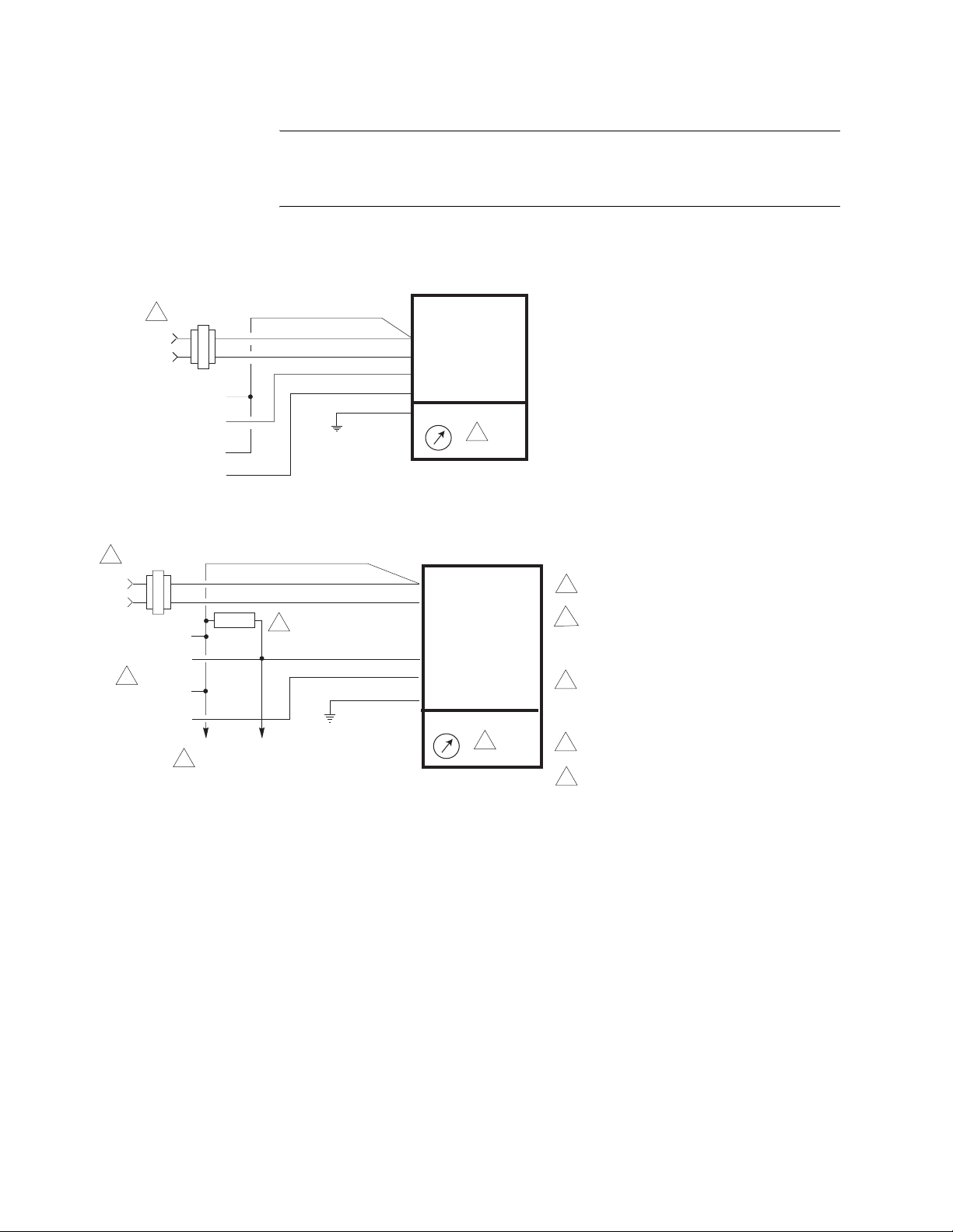
TYPICAL PROPORTIONAL CONTROL (wiring diagrams)
Figure-6 illustrates typical wiring diagrams for MSx1-7203 Series proportional spring return
actuators. See Table-1 for model selection.
Line
Volts
Control Signal
2 to 10 Vdc
Feedback Signal
2 to 10 Vdc
Transformer
1
or 22- 30 Vdc
Line
Volts
Control Signal
4 to 20 mA
4
Feedback Signal
2 to 10 Vdc
Caution:
powered off transformers used to power other devices utilizing non-isolated full-wave
rectifier power supplies. Refer to
Common Transformer, F-26363
2 to 10 Vdc Proportional Control
24 Vac
Transformer
1
or 22- 30 Vdc
Gra
Blk
Red
Yel/Blk
Blu AO
(-)
(+)
(-)
(+)
4 to 20 mAdc Proportional Control
24 Vac
Com
Com
Yel/Blk
Blu
(-)
(+)
500 Ω
Gra
Blk
3
(-)
(+)
To Additional
2
Actuators
This product contains a half-wave rectifier power supply and must not be
EN-206, Guidelines for Powering Multiple Devices from a
for detailed information.
AI
AO
MSX1-7203
L R
MSX1-7203
L R
5
1 Provide overload protection and disconnect
as required.
2 With four actuators wired to one 500 ohm
resistor, a +2% shift of the control signal
may be required. (Actuator input impedance
is 80 k ohm.)
3 A field-supplied 500 ohm resistor (AM-708)
is required between the gray and
yellow/black leads to convert the 4 to 20
mAdc control signal to 2 to 10 Vdc.
5
4 Only connect common to negative (-) leg of
control circuits.
5 To reverse actuator control function
(direct/reverse action), use the reversing
switch, see Figure-9.
Com
Com
Hot (+DC)
AI
Grn/Yel
Hot (+DC)Red
Grn/Yel
Figure-6 Typical Wiring Diagrams for Proportional Control 24 Vac Basic Models.
8 © Copyright 2006 TAC All Rights Reserved. F-27120-4
Page 9
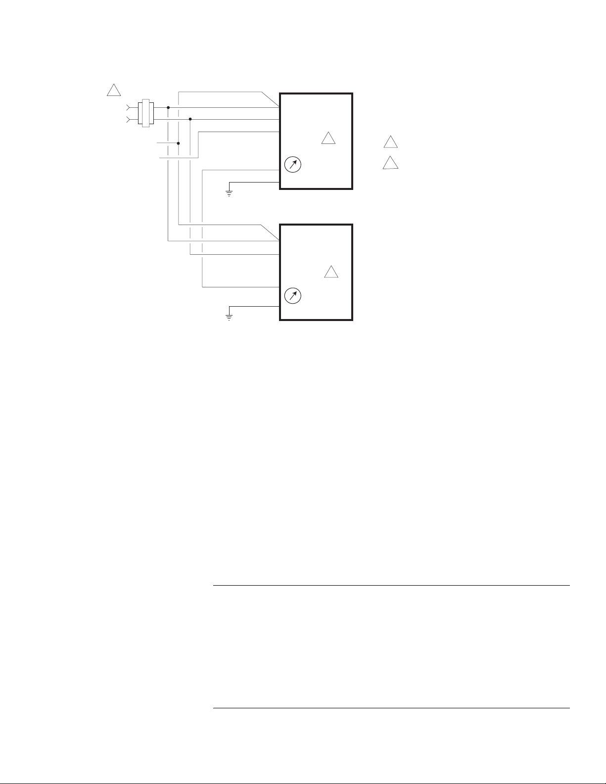
1
Line
Volts
Control Signal
2 to 10 Vdc
Two Actuators Wired in Parallel
24 Vac
Transformer
or 22- 30 Vdc
Gra
Blk
Red
Yel/Blk
Com
Com
Hot (+DC)
AI
(-)
(+)
Blu
AO
Grn/Yel
MSX1-7203
L R
2
1 Provide overload protection and disconnect
as required.
2 To reverse actuator control function
(direct/reverse action), use the reversing
switch, see Figure-9.
Gra
Blk
Red
Yel/Blk
Figure-7 Typical Wiring Diagrams for Proportional Control 24 Vac Models Wired in Parallel.
Com
Com
Hot (+DC)
AI
Grn/Yel
MSX1-7203
2
L R
INSTALLATION
Inspection Inspect the package for damage. If damaged, notify the appropriate carrier immediately. If
undamaged, open the package and inspect the device for obvious damage. Return
damaged products.
Requirements • Job wiring diagrams
• Appropriate accessories
• Pliers for removing and inserting connecting pin
• Installer must be a qualified, experienced technician
• Tool-37, 1-1/2" to 3" adjustable spanner wrench for valve mounting nut
• 5/16" (Tool-20-1) and 3/4" open-end wrench for stem jam nuts
• 1/8" Allen wrench
• Size 10 IP Torx Plus bit (Mx51 units only)
Precautions General
Warning:
• Electrical shock hazard! Disconnect the power supply (line power) before installation to
prevent electric shock and equipment damage.
• Make all connections in accordance with the job wiring diagram and in accordance with
national and local electrical codes.
• Floating and Proportional Models: These products contain a half-wave rectifier power
supply. They must not be powered with transformers that are used to power other
devices utilizing non-isolated full-wave rectifier power supplies. Refer to EN-206,
Guidelines For Powering Devices From A Common Transformer, F-26363 for detailed
information.
F-27120-4 © Copyright 2006 TAC All Rights Reserved. 9
Use copper conductors only.
Page 10
Caution:
• Avoid electrical noise interference. Do not install near large contactors, electrical
machinery, or welding equipment.
• Manual override to be used only when power is not applied to unit.
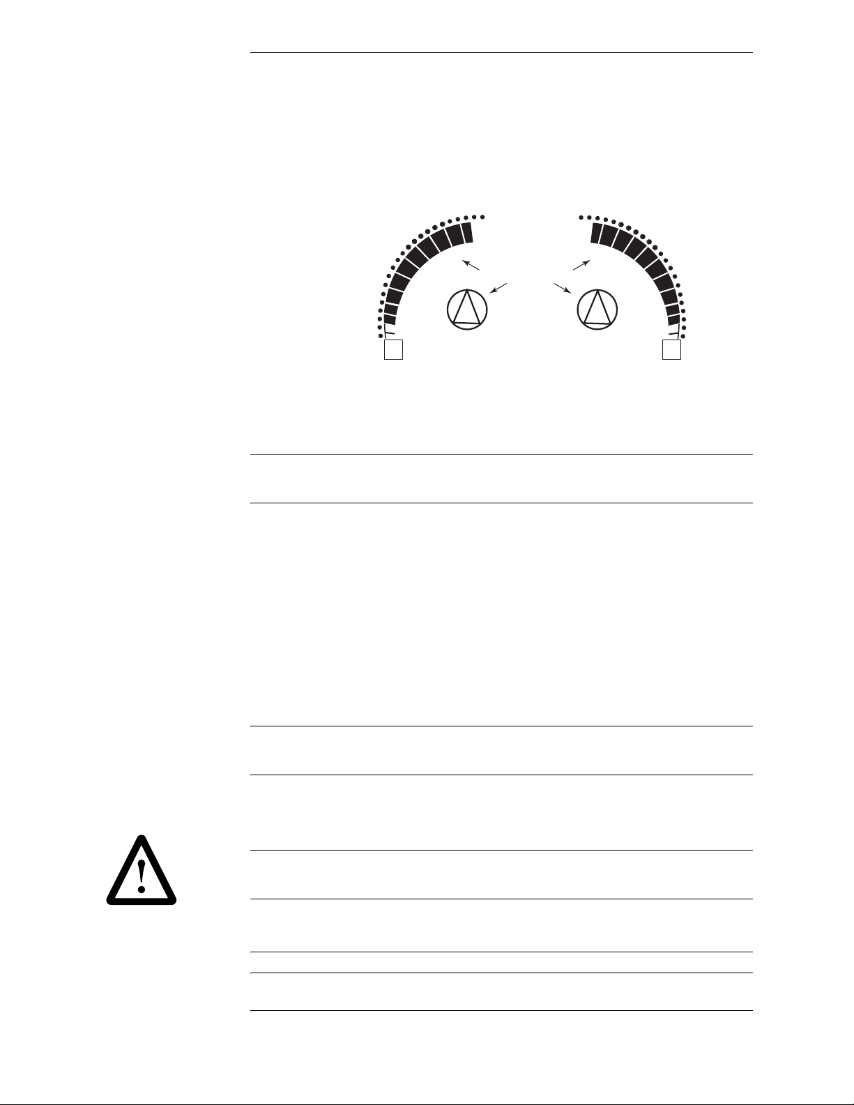
• When operating manual override (observe position indicator, Figure-8), back off 5°
(1/2 turn counter clockwise) from full extended mechanical stop to ensure proper
release.
90
80
70
60
50
40
30
20
10
0
-5
Scale markings indicate
degrees rotation of hub
90
80
70
60
50
40
30
20
10
0
-5
LR
Figure-8 Position Indicator
• Do not drill holes in actuator body. Six pre-drilled holes are located on each side, under
crosshairs on the label, to accept #10-24 thread-forming screws for mounting
accessories.
Federal Communications Commission (FCC)
Note:
This equipment has been tested and found to comply with the limits for a Class B
digital device, pursuant to Part 15 of the FCC Rules. These limits are designed to provide
reasonable protection against harmful interference in residential installations. This
equipment generates, uses, and can radiate radio frequency energy and may cause
harmful interference if not installed and used in accordance with the instructions. Even
when instructions are followed, there is no guarantee that interference will not occur in a
particular setting—Which can be determined by turning the equipment off and on—the user
is encouraged to try to correct the interference by one or more of the following measures:
• Reorient or relocate the receiving antenna.
• Increase the separation between the equipment and receiver.
• Connect the equipment to an outlet on a circuit different from that to which the receiver
is connected.
• Consult the dealer or an experienced radio/television technician for help.
Canadian Department of Communications (DOC)
Note:
This Class B digital apparatus meets all requirements of the Canadian InterferenceCausing Equipment Regulations.
Cet appareil numerique de la classe B respecte toutes les exigences du Reglement sur le
material broilleur du Canada.
European Standard EN 55022
Warning:
environment this product may cause radio interference in which case the user may be
required to take adequate measures.
Location
Caution:
explosive vapors are present.
10 © Copyright 2006 TAC All Rights Reserved. F-27120-4
This is a Class B digital (European Classification) product. In a domestic
Avoid locations where excessive moisture, corrosive fumes, vibration, or
Page 11
Mounting • Mount the linear actuator directly on the valve in locations that clear the maximum
dimensions of the actuator case (see Figures 19 and 20).
• Ensure that the valve body is installed correctly. The arrow must point in the direction
of flow. With three-way valves observe stem position (stem up) for proper flow
characteristics. See Table-2.
• The actuator must be mounted above the centerline of the valve body. This will
minimize the risk of damage to the actuator in the event of condensation. Refer to
Figure-15, Figure-16, and Figure-17.
Actuator Selection
Mx51 series actuators are used on 1-1/4" to 2" VB-7xxx valves. Mx61 series actuators are
used on 2-1/2" to 4" VB-931x, 2-1/2" to 5" VB-8xxx, and discontinued 1-1/2” to 4” VB-9xxx
valves (with AM-733 or AM-734kit purchased separately).
Changing Control Function (proportional units only)
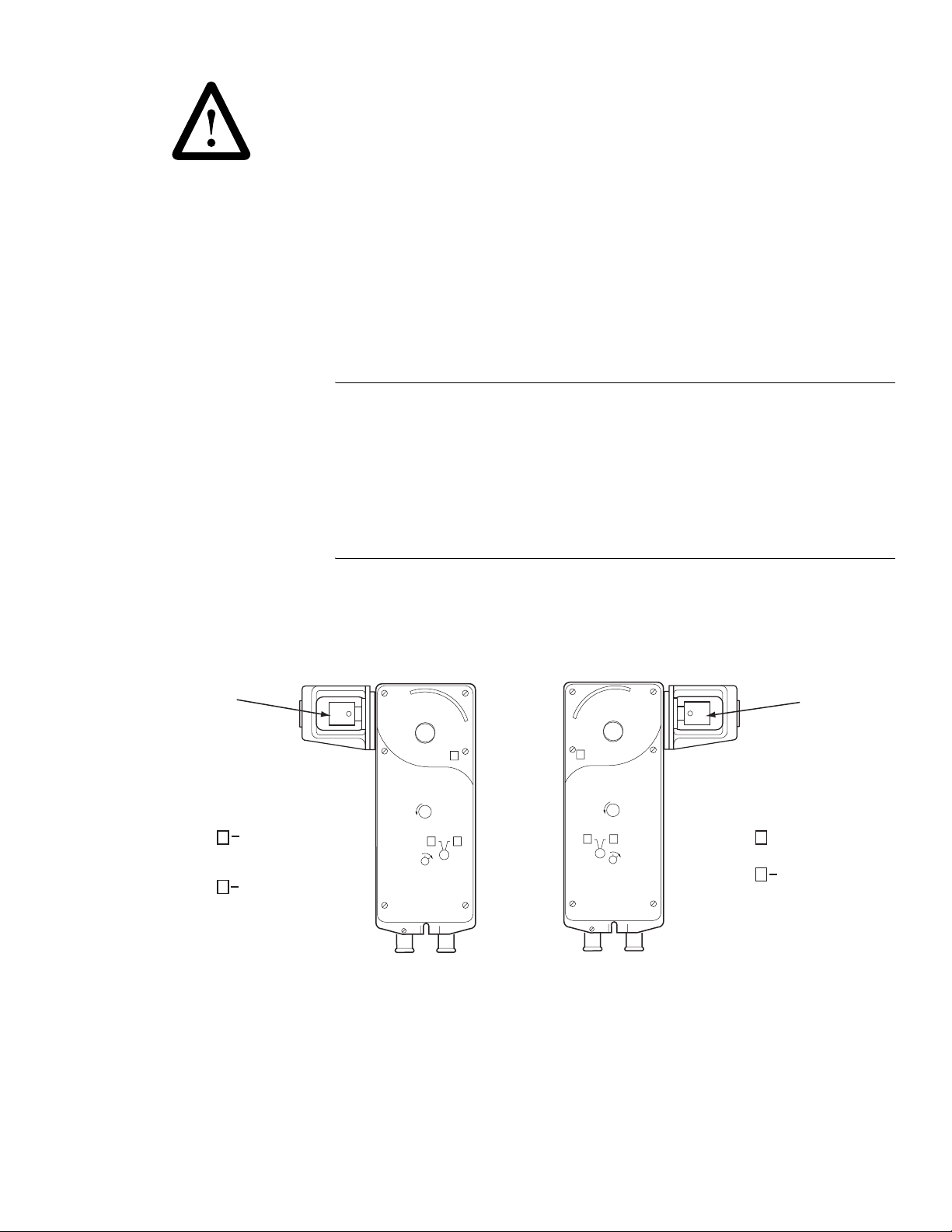
These actuators are equipped with a switch to control the function of the signal as received.
See Figure-9.
Rack
Switch on R
Switch on L
Caution:
moves the actuator against the -5° positive stop. Example: Viewing the actuator from the
left side with the switch set to “R” and an increasing signal. The actuator will attempt to
rotate beyond the -5° stop and will stall.
Rack extends on
increasing signal
Rack retracts
on increasing signal
These are spring return actuators. It is possible to switch to a direction that
• Install all two-way valves so that they close against the flow. An arrow on the valve body
or a tag indicates the proper flow direction.
• Always install three-way mixing valves with two inlets and one outlet.
• Install three-way diverting valves with one inlet and two outlets. When piped for mixing,
Cv’s may differ slightly.
Viewed from "R" side:
R
R
L
LOCK
Viewed from "L" side:
L
R
L
LOCK
Switch on L
Switch on R
Rack
Rack extends
on increasing signal
Rack retracts on
increasing signal
Figure-9 Rotation Switch Settings for MSx1-7203 Proportional Actuators.
F-27120-4 © Copyright 2006 TAC All Rights Reserved. 11
Page 12
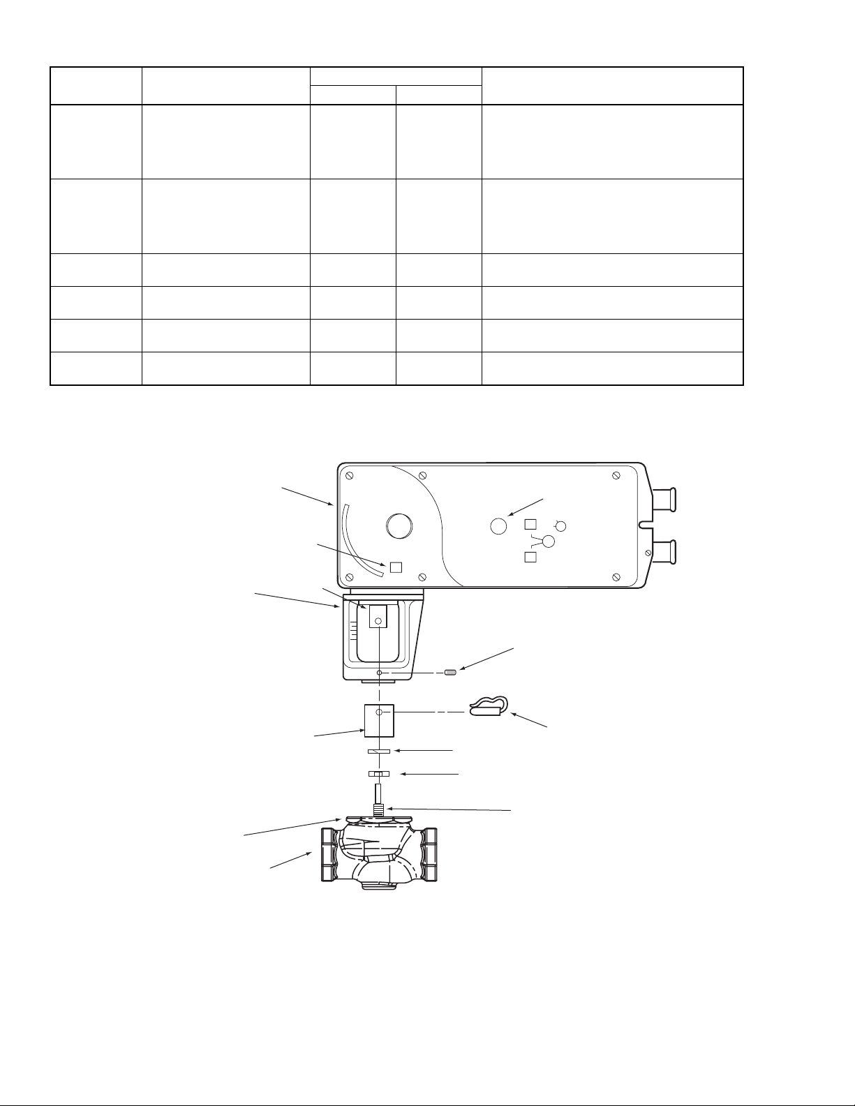
Table-2 Valve Configuration Chart.
Valve Body Valve Body Action
VB-721x
VB-7253
VB-7273
VB-821x
VB-921x
Two-Way Stem Up Open Up Open Port A to AB flow decreases as actuator extends
a
VB-722x
VB-7263
VB-7283
VB-822x
VB-922x
VB-731x
VB-931x
Two-Way Stem Up Closed Up Closed Port A to AB flow increases as actuator extends
a
Three-Way Mixing Up B to AB
VB-732x Three-Way Diverting Up B to AB
VB-8303 Three-Way Piped as Mixing
VB-8303 Three-Way Piped as Diverting
a
Discontinued.
b
Universal diverting/mixing valve, may be piped as either mixing or diverting.
b
b
Normal Position
Valve Stem Flow
Up AB to B
Up B to AB
Action
Port A to AB flow increases as actuator extends
Port B to AB flow decreases as actuator extends
Port B to A flow increases as actuator extends
Port B to AB flow decreases as actuator extends
Port A to B flow increases as actuator extends
Port AB to B flow decreases as actuator extends
Port B to A flow increases as actuator extends
Port B to AB flow decreases as actuator extends
Linear Actuator
Mounting Bracket
Stem Extension
Hex Mounting Nut*
Valve Body*
Label
Rack
Manual Override
L
L
R
Set Screw
Connecting Pin
Lock Washer
Jam Nut
Valve Stem*
* Not included with linear actuator.
Figure-10 Mx51-720x Series Actuator Exploded View.
12 © Copyright 2006 TAC All Rights Reserved. F-27120-4
Page 13
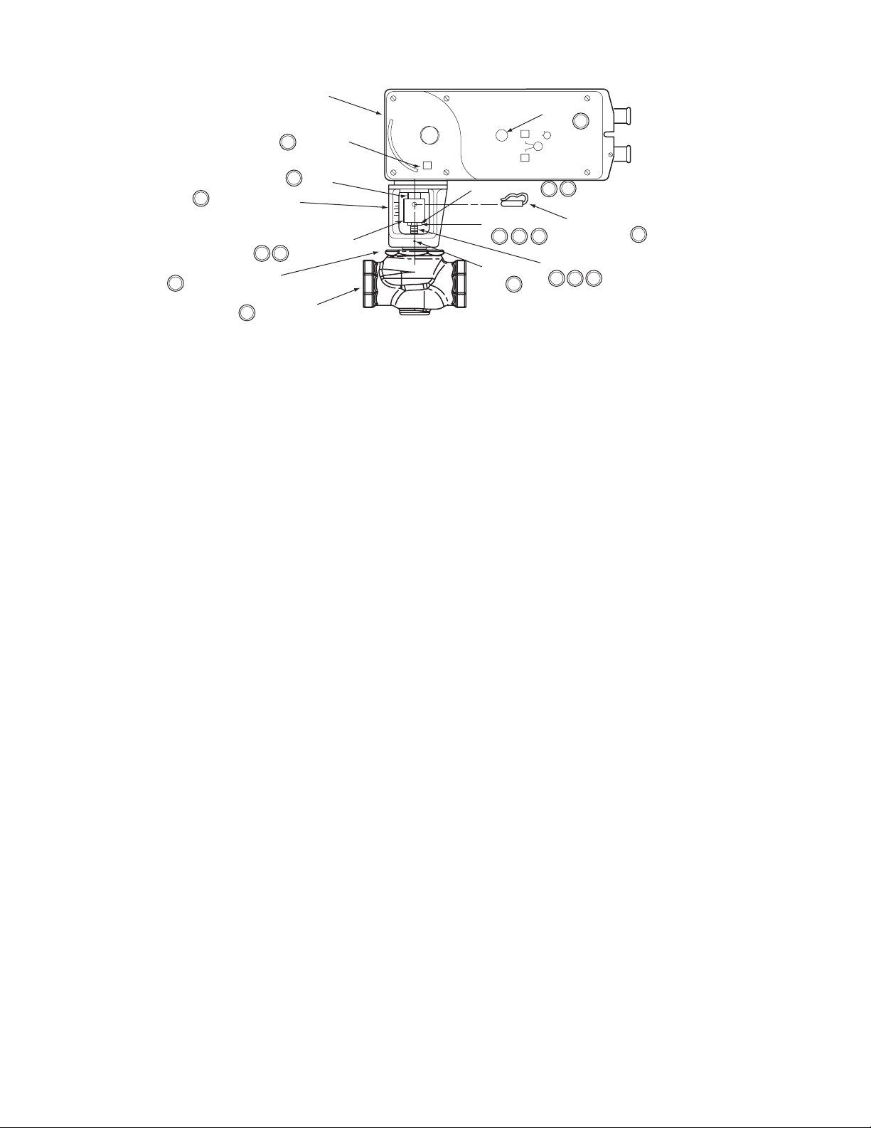
6
Mounting Bracket
Hex Mounting Nut*
6
6
Figure-11 Typical Assembly and Installation of Mx51 Series Actuator to 1-1/4" to 2" VB-7xxx Series Valve Bodies, Stem-Up Closed or Open, 2-Way and 3-Way Valves.
Linear Actuator
Label
8
(both sides)
7
Rack
Stem Extension
74
Valve Body*
Installation: Mx51-720x Series Actuator to 1-1/4" to 2" VB-7xxx Series Valve Bodies, Stem-Up Closed or Open, 2-Way and 3-Way
A. Install the actuator onto the valve. Set up the assembly according to the numbered steps
B. Apply power to the actuator and check the system operation for heating or cooling output
Manual Override
L
L
Lock Washer
Jam Nut
Set Screw
R
2
1
9
5
4
3
Connecting Pin
7
Valve Stem*
3
2
7
6
*Not included with linear actuator.
in Figure-11.
1. Locate the jam nut that came packaged with the actuator.
2. Screw the jam nut onto the valve stem all the way as far as it will go. You may need to use a 5/16" (Tool-20-1) open-end wrench. At least 1/2" of the valve stem threads should extend above the nut.
3. Place lock washer over valve stem.
4. Thread the stem extension onto the valve stem, making contact with the lock washer and jam nut.
5. Ensure 15° or 1-1/2 turns of manual override for actuator preload. See Figure-18.
6. Orient the actuator mounting bracket on the valve and tighten the mounting nut securely against the bracket using Tool-37. Raise the valve stem to the full up position.
7. Rotate stem extension until the through hole lines up with the through hole of actuator rack. Insert connecting pin to secure stem extension and tighten jam nut against stem extension using 5/16" (Tool-20-1) open end wrench.
8. Affix open/closed label to the indicator in the appropriate position.
9. Insert set screw (packaged with actuator) into the most accessible side. Tighten with size 10 IP Torx Plus bit to 20 - 25 lb-in (2.3 to 2.8 N-m).
in response to the control signal.
F-27120-4 © Copyright 2006 TAC All Rights Reserved. 13
Page 14
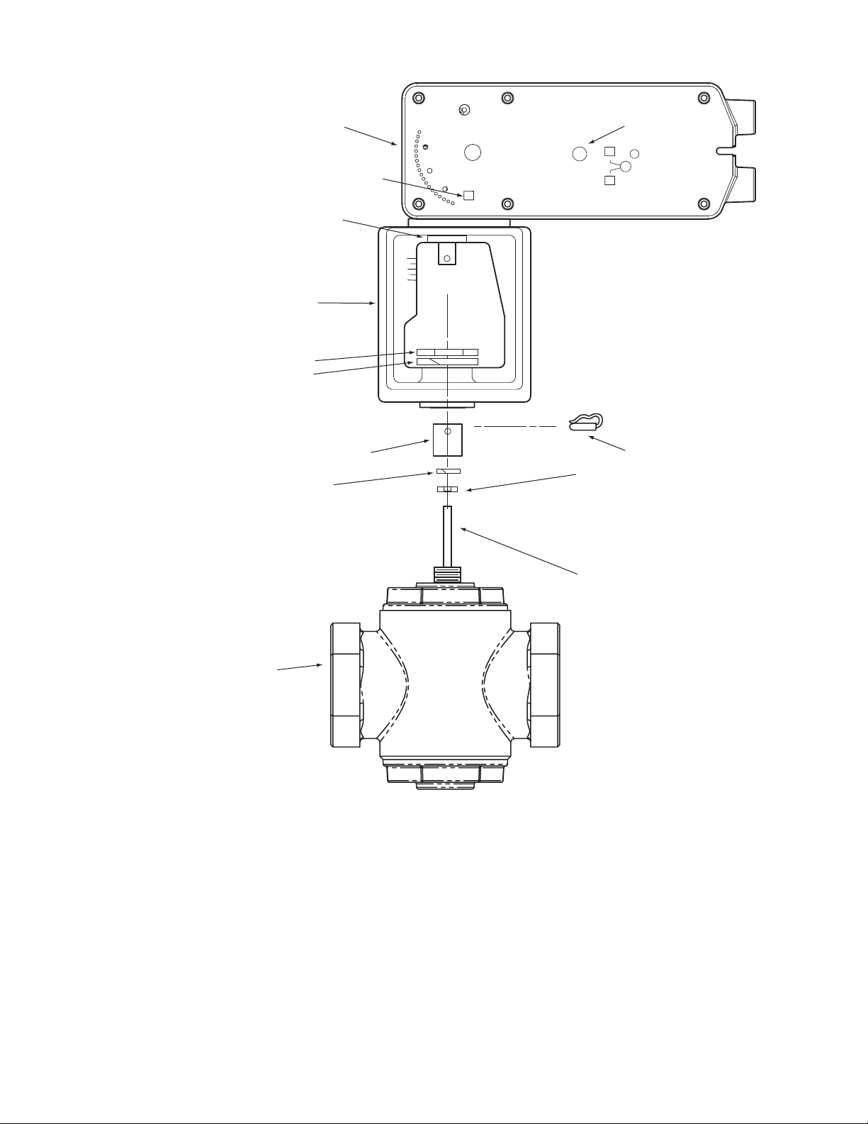
Linear Actuator
Mounting Bracket
Hex Mounting Nut*
Lock Washer
Rack
Label
Manual Override
L
R
L
Lock Washer
Valve Body*
Stem Extension
Figure-12 Mx61-720x Series Actuator Exploded View.
Connecting Pin
Jam Nut
Valve Stem*
* Not included with linear actuator.
14 © Copyright 2006 TAC All Rights Reserved. F-27120-4
Page 15
Linear Actuator
7
(both sides)
6
Rack
Label
Manual Override
L
R
L
5
5
Mounting Bracket
Mounting Nut*
5
Lock Washer
5
Valve Body*
5
Stem Extension
63
Connecting Pin
Lock Washer
Jam Nut
3
1
2
Valve Stem*
32
2
6
5
*Not included with linear actuator.
6
3
5
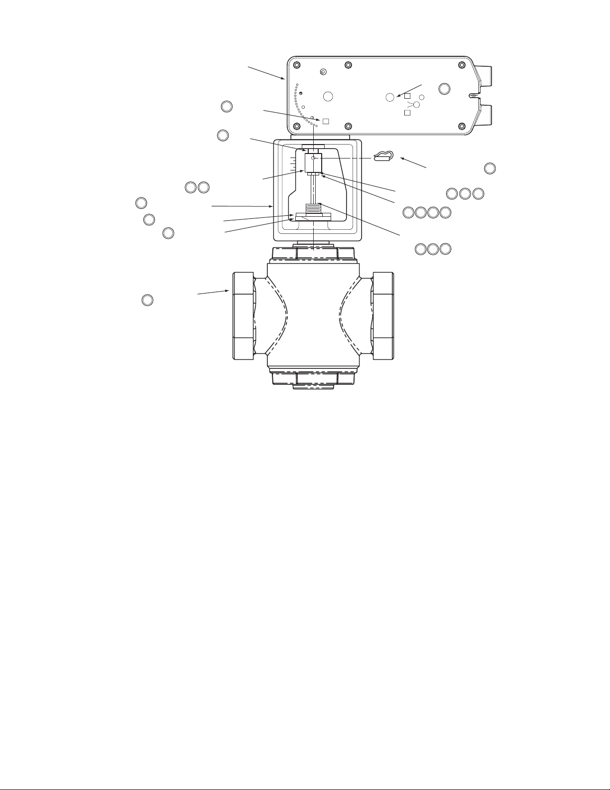
Figure-13 Typical Assembly and Installation.
Installation: Mx61-720x Series Actuator to 2-1/2" to 4" VB-9xxx and 2-1/2" to 5" VB-8xxx Series Valve Bodies, Stem-Up Closed 2-Way and 3-Way
A. Install the actuator onto the valve. Set up the assembly according to the numbered steps
in Figure-13.
1. Locate the jam nut that came packaged with the actuator.
2. Screw the jam nut onto the valve stem all the way as far as it will go (you may need to use a 3/4" open-end wrench). At least 1/2" of the valve stem threads should extend above the nut. Place the lock washer over the valve stem.
3. Thread the stem extension onto the valve stem, making contact with the lock washer and jam nut.
4. Ensure 15° or 1-1/2 turns of manual override actuator preload. See Figure-18.
5. Orient the actuator mounting bracket on the valve, place lock washer over valve stem and tighten the mounting nut securely against the bracket using spanner wrench. Raise the valve stem to the full up position.
6. Rotate stem extension until the through hole lines up with the through hole of actuator rack. Insert connecting pin to secure stem extension and tighten jam nut against stem extension using 3/4" open end wrench.
7. Affix open/closed label to the indicator in the appropriate position.
B. Apply power to the actuator and check the system operation for heating or cooling output
in response to the control signal.
F-27120-4 © Copyright 2006 TAC All Rights Reserved. 15
Page 16
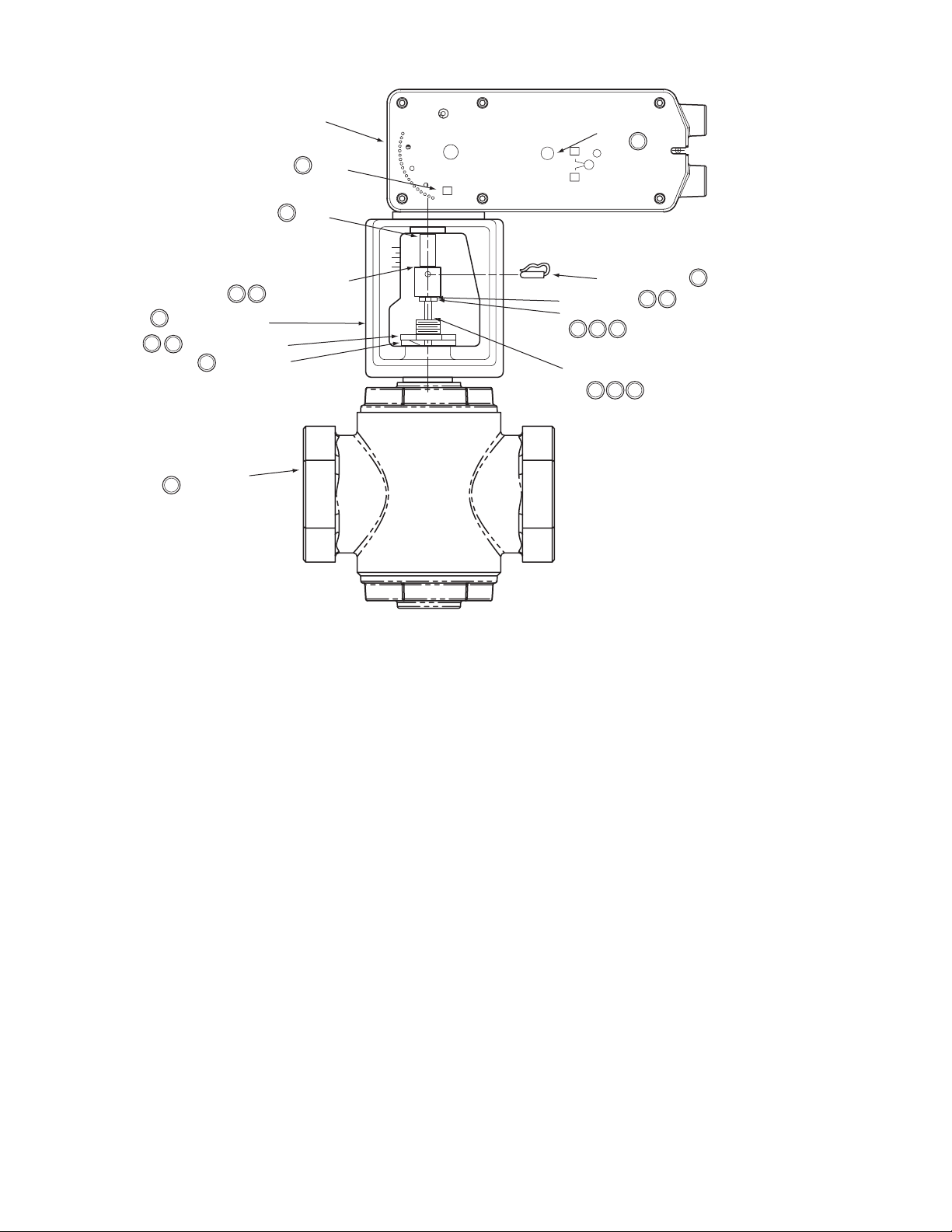
Linear Actuator
7
(both sides)
6
Rack
Label
Manual Override
L
R
L
5
4
Mounting Bracket
Mounting Nut*
2
4
4
Valve Body*
4
Stem Extension
63
Lock Washer
Connecting Pin
Lock Washer
Jam Nut
6
3
1
Valve Stem*
3
2
42
6
3
*Not included with linear actuator.
Figure-14 Typical Assembly and Installation.
Installation: Mx61-720x Series Actuator to 2-1/2" to 4" VB-9xxx Series and 2-1/2" to 5" VB-8xxx Valve Bodies, 2-Way Stem-Up Open
A. Install the actuator onto the valve. Set up the assembly according to the numbered steps
in Figure-14.
1. Locate the jam nut that came packaged with the actuator.
2. Screw the jam nut onto the valve stem all the way as far as it will go (you may need to use a 3/4" open-end wrench). At least 1/2" of the valve stem threads should extend above the nut. Place the lock washer over the valve stem.
3. Thread the stem extension onto the valve stem, making contact with the lock washer and jam nut.
4. Orient the actuator mounting bracket on the valve. Place lock washer over valve stem and tighten the mounting nut securely against the bracket using spanner wrench. Ensure the valve stem is completely pushed down.
5. Insert the hex wrench into manual override and crank to extend the actuator rack to its fully extended position, back off 1-1/2 turn, and lock (see Figure-18). Remove hex wrench to prevent accidental spring return of the actuator.
6. Rotate stem extension until the through hole lines up with the through hole of actuator rack. Insert connecting pin to secure the assembly. Tighten jam nut against stem extension using 3/4" open end wrench.
7. Affix open/closed label to the indicator in the appropriate position.
B. Apply power to the actuator and check the system operation for heating or cooling output
in response to the control signal.
16 © Copyright 2006 TAC All Rights Reserved. F-27120-4
Page 17
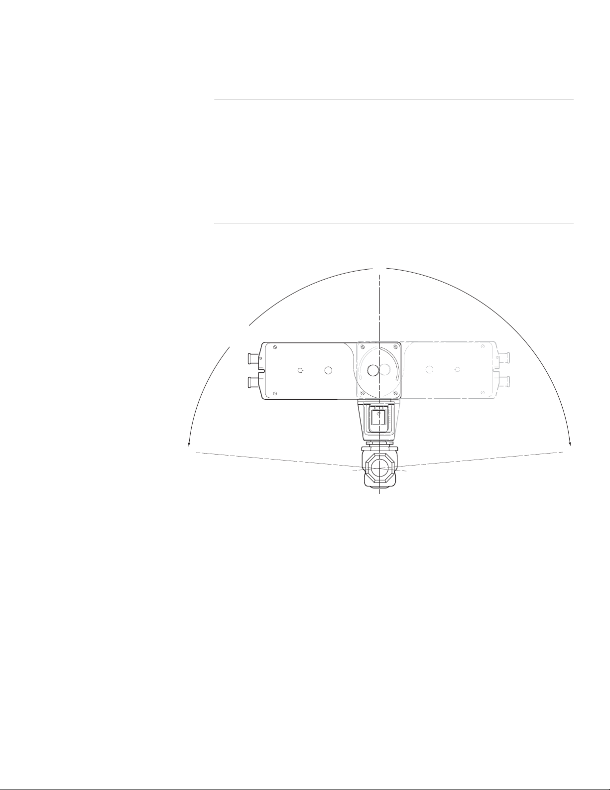
Valve Mounting The valve should be mounted in a weather-protected area, in a location that is within the
ambient temperature limits of the actuator. The installation of the actuator assembly should
provide clearance on all sides to allow for any maintenance that may be needed (see
Figure-15 and Figure-17). Install the valve according to the instructions in the appropriate
valve body General Instructions sheet (see Applicable Literature, page 2).
Caution:
Linear actuators are designed to effectively support its own weight. No load or
weight should be resting on the actuator as long term damage may occur to the actuator,
the mounting connection, or the valve.
• Do not insulate the actuator/linkage. Doing so will result in excess heat buildup within
the actuator.
• On non-steam applications the globe valve assembly must be mounted so that the
actuator is at least 5° above the horizontal (Figure-15) to ensure that any condensate
that forms will not travel into the mounting bracket or actuator.
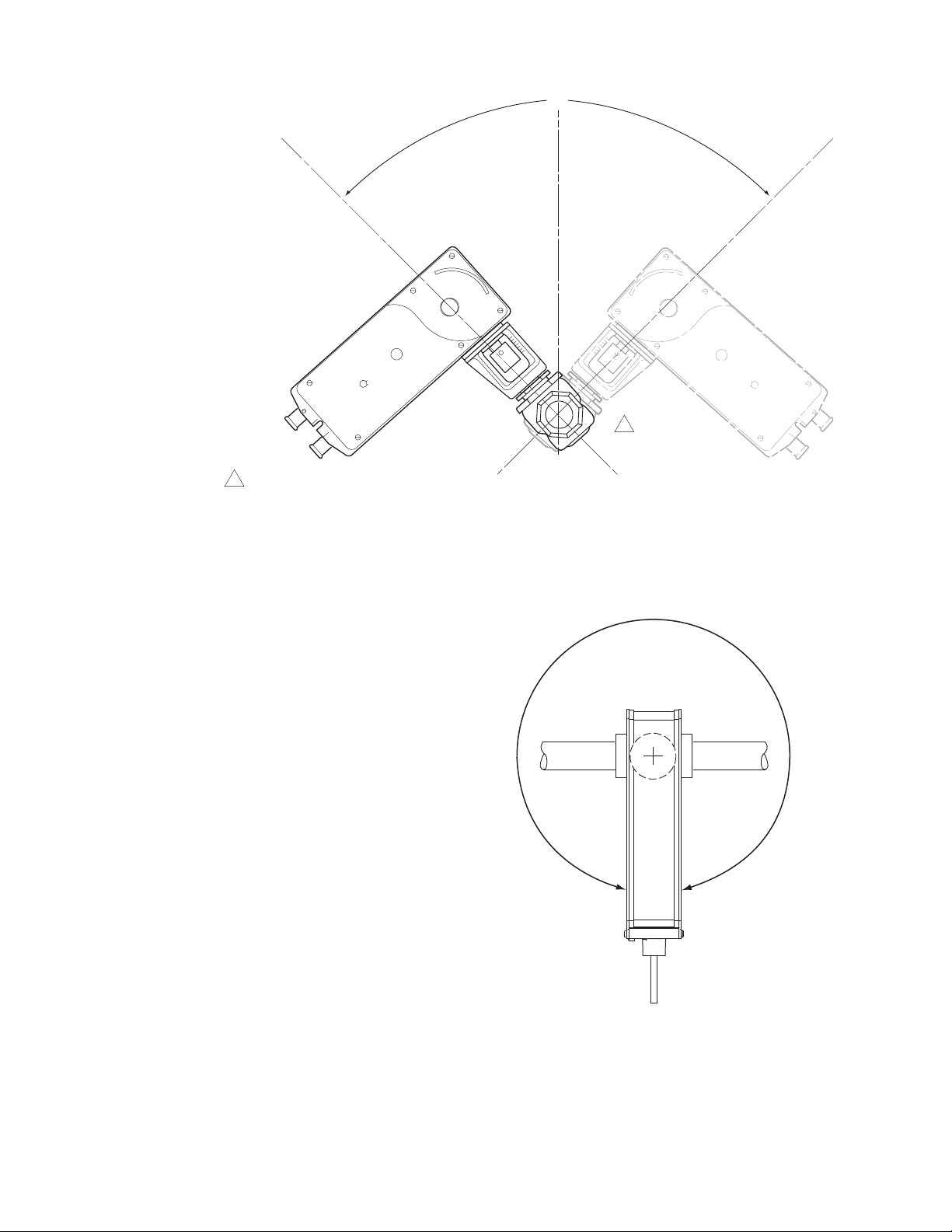
• On steam applications, the globe valve assembly must be mounted at 45° from
vertical. (Figure-16).
Mounting Angle Range for
Non-steam Applications
(either side)
0°
85°
85°
Figure-15 Typical Mounting Position.
F-27120-4 © Copyright 2006 TAC All Rights Reserved. 17
Page 18
0°
45°
1 For steam applications the valve assembly
must be mounted in piping at a 45° angle
(either side).
Figure-16 Typical Mounting Position for Steam Applications.
45°
1
360° Rotation Range
Figure-17 Actuator Positioned Anywhere Within 360 Degrees.
18 © Copyright 2006 TAC All Rights Reserved. F-27120-4
Page 19
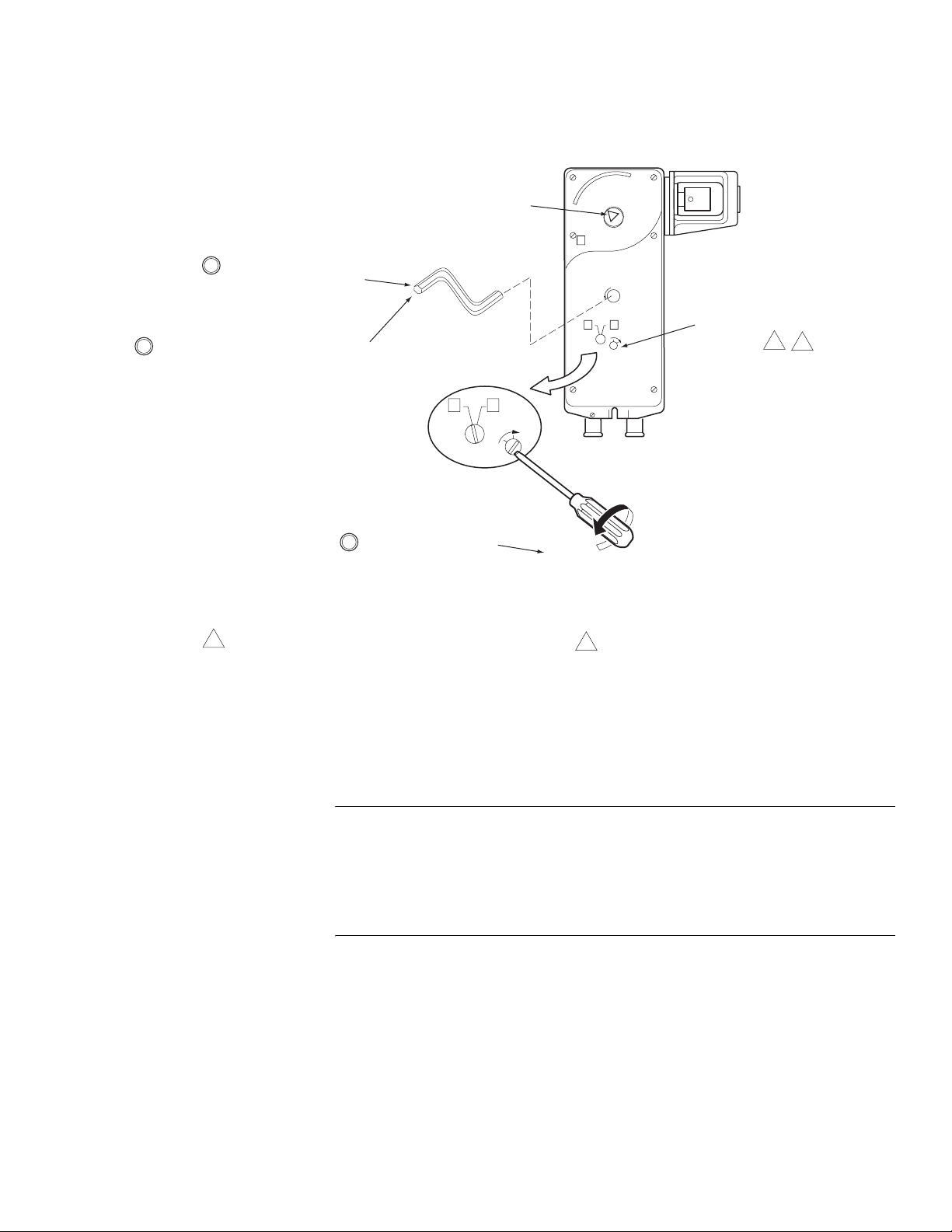
MANUAL OVERRIDE OPERATION
Insert the hex wrench fully
1
into the manual override
mechanism.
Rotation Indicator
Triangle
L
Unlock the manual override, using the
2
hex wrench. To do this, turn, then release
the hex wrench approximately 5° (1/2 turn)
CW, to "jog" the mechanism and release the
manual override preset.
3
1
When necessary, the manual override mechanism may be
used to reposition the actuator at any point between -5°
and 85°. This mechanism is accessible on both sides of
the actuator and can be used to ensure tight close-offs for
valves.
R
L
LOCK
When finished, lock the
manual override by turning
the screwdriver CW (in the
direction of the arrow).
Figure-18 Manual Override.
Unlock
R
L
LOCK
When using the manual override mechanism:
2
Manual Override Locking
Mechanism
1
2
• Fully engage the hex wrench in the manual
override before cranking.
• When operating the manual override, ensure
proper release by backing off 5° from the full
extended mechanical stop.
Caution:
• Only use manual override when the actuator drive motor is not powered.
• Engaging the manual override when the actuator is powered will cause damage to the
gears.
• Using power tools to adjust the override will cause damage to the gears.
• Avoid manually repositioning the actuator beyond its adjustable travel limit setting.
F-27120-4 © Copyright 2006 TAC All Rights Reserved. 19
Page 20

Wiring Requirements Control Leads
See Table-3 for power wiring data. Refer to Figure-1 through Figure-7 for typical wiring.
Table-3 Power Wiring.
Actuator
Voltage
24 Vac
22-30 Vdc
CHECKOUT
After the entire system has been installed and the actuator has been powered up, the
following check can be made for proper system operation. Check for correct operation of the
valve while actuator is being stroked.
1. Apply power to the actuator. Actuator and valve should be driven to their powered position as determined by the control signal.
2. Remove power from the actuator. Actuator and valve should return to the spring return position.
Note:
Check that the transformer(s) are sized properly. (24 Vac)
• If a common transformer is used with multiple actuators, make sure that polarity is
observed on the secondary. This means connecting all black wires to one leg of the
transformer and all red wires to the other leg of the transformer.
• If multiple transformers are used with one control signal, make sure all black wires are
tied together and tied to control signal negative (-).
• If the controller uses a full-wave power supply and does not provide isolated outputs, a
separate transformer is required.
Part Number
MAx1-7203 —
MFx1-7203
MSx1-7203
12 AWG14 AWG16 AWG18 AWG20 AWG22 AWG
500
(152)
600
(183)
Maximum Wire Run in ft. (m)
330
(101)
300
(91)
380
(116)
200
(61)
200
(61)
240
(73)
130
(40)
130
(40)
150
(46)
——
80
(24)
90
(27)
50
(15)
60
(18)
THEORY OF OPERATION
MAINTENANCE
The MA, MF and MS series actuators are directly mounted onto the valve without the use of
separate linkage. They are equipped with true mechanical spring return operation for
reliable, positive actuator operation in the unpowered condition.
Linear series actuators use a brushless DC motor which is controlled by a microprocessor.
The microprocessor supplies the intelligence to provide a constant motion rate and to know
the actuator’s exact normal position and to match actuator mechanical stroke to the control
input signal range on proportional (MS) models. The microprocessor monitors and controls
the brushless DC motor’s rotation and provides a digital rotation sensing function to prevent
damage to the actuator in a stall condition. The actuator may be stalled anywhere in its
normal rotation without the need of mechanical switches.
When power is applied to two-position (MA) models, the actuator moves to its full stroke
position, at the same time tensing the spring return mechanism. When power is removed,
the spring returns the actuator to its normal position.
When power is applied to floating (MF) and proportional (MS) models, the actuator first
moves to its zero position, then moves to the position dictated by the control input signal.
For proportional (MS) models, when the actuator encounters a stall condition (end of valve
stroke), it recalibrates itself if necessary so that its mechanical stroke matches the control
signal input span. The feedback signal range is also matched to the mechanical stroke. If
power is lost, the actuator spring returns to its normal position.
Regular maintenance of the total system is recommended to assure sustained optimum
performance. The Linear series actuators are maintenance free.
20 © Copyright 2006 TAC All Rights Reserved. F-27120-4
Page 21
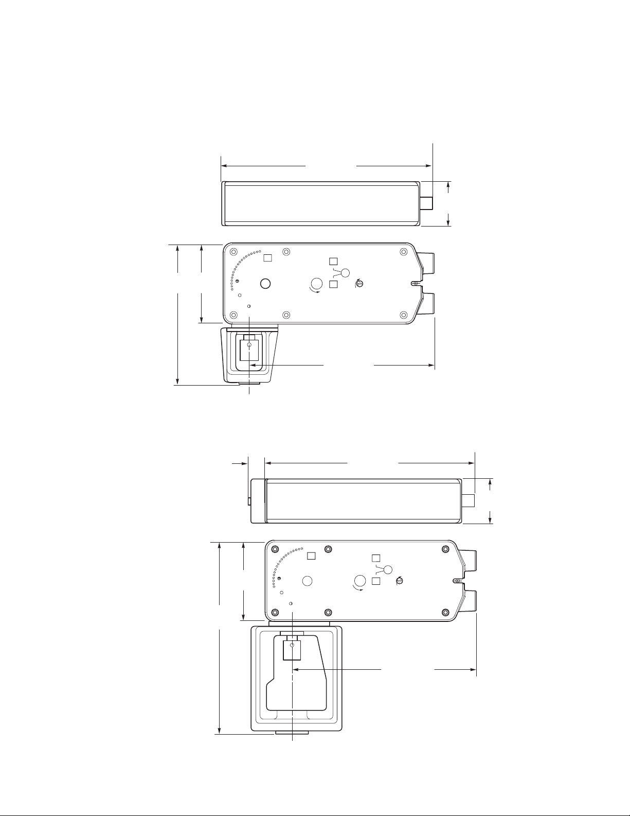
FIELD REPAIR
DIMENSIONAL DATA
Actuator: None. For replacement contact your TAC Representative and specify the desired
model number from Table 1.
Linkage parts: All are supplied with the actuator. Stem extension, jam nut, washer, and
connecting pin may be purchased separately if lost. See ACCESSORIES, page 4.
10-9/16 (268)
2-33/64
(64)
7
(178)
4
(103)
R
L
LOCK
R
9-1/4 (235)
Minimum clearance: 5" for actuator removal.
Figure-19 Mx51-720x Spring Return Valve Actuator Dimensions.
9/16
(14)
R
4
(103)
10-9/16 (268)
L
R
LOCK
Dimensions shown
are in inches (mm).
2-33/64
(64)
9-1/2
(241)
Dimensions shown
are in inches (mm).
9-1/4 (235)
Minimum clearance: 5" for actuator removal.
Figure-20 Mx61-720x Spring Return Valve Actuator Dimensions.
F-27120-4 © Copyright 2006 TAC All Rights Reserved. 21
Page 22

22 © Copyright 2006 TAC All Rights Reserved. F-27120-4
Page 23

F-27120-4 © Copyright 2006 TAC All Rights Reserved. 23
Page 24

Copyright 2006, TAC
All brand names, trad emarks and registered
trademarks are the property of their respective
owners. Information contained within this
document is subject to change without notice.
F-27120-4
TAC
1354 Clifford Avenue
P.O. Box 2940
Loves Park, IL 61132-2940
www.tac.com
 Loading...