

System Sensor SpectrAlert S900RLFIRE, SpectrAlert S900RL Installation And Maintenance Instructions Manual
Page 1
1 I56-4019-000
INSTALLATION AND MAINTENANCE INSTRUCTIONS
For use with the following models:
S
900RL and S900RLFIRE
SpectrAlert Strobe
SPECIFICATIONS
Size:
Weight:
Operating Temperature Range:
Rated Supply Voltage:
Operating Voltage Range:
Max Operating Current:
Flash Frequency:
Location:
Software Ver.
142.7mmX 126.2mm X 62mm
129g
-10
°C
to 55°C
24VDC
19-30VDC
30mA@24V
1.0Hz
Non-residential construction (Indoor)
A
GENERAL DESCRIPTION
The S900RL and S900RLFIRE SpectrAlert strobes by Syste
m
Sensor are a series of visual signaling devices for use on fir
e
alarm applications. The S900RLFIRE strobe has the word ‘FIRE
’
printed in 25mm height lettering on the cover, whereas th
e
S900RL has a plain cover. These strobes are designed to be use
d
on 24 Volt DC systems and have low operating current. Whe
n
these strobes operate on the rated supply voltage, they will flas
h
once per second until the power supply is switched off.
Note: They are not compatible for use with MDL or MDL
3
synchronization modules or coded power supplies.
STROBE OPERATING CONSIDERATIONS:
Generally, for purposes of determining the wire size necessary
for the system, it is best to consider all of the devices as
“lumped”on the end of the supply circuit
(simulates “worst case”).
Typical wire size resistance:
18AWG Solid:
16AWG Solid:
14AWG Solid:
12AWG Solid:
Example: Assure you have 10 devices on a zone and each
require 50mA average and 2,000m of 14 AWG wire (total
length= outgoing + return).
The voltage at the end of the loop is
0.050amps per device x 10 devices x 10ohms/1,000m x 2,000m
=10 volts drop.
The same number of devices using 12
A
WG wire produce only 7
volts drop. The same devi ces u sin g 18 AW G wire will p rod uce
27 volts. Consult your panel manufacturer’s specifications, as
well as SpectrAlert’s operating voltage range to determine
acceptable voltage drop.
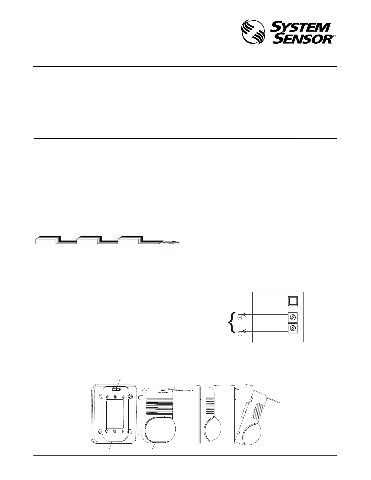
Ter min al Diagram
:
27
Ω/1,000m
17Ω/
1,000m
10Ω/
1,000m
7Ω/
1,000m
POWER SUPPL
Y
CONSIDERATIONS
Power System supply DC filtered voltage. The system design
engineer must calculate the
num
ber of units used in a zone
based on the type of power supply.
Be certain the sum of all the device currents do not exceed the
current capability of the supply in order to assure the product
can work normally.
WIRE SIZE
The designer must be sure that the l ast device on the circuit has
sufficient voltage to operate the device within its rated voltage.
When calculating the voltage available to the last device. It is
necessary to consider the voltage drop due to the resistance
of the wire. The thicker the wire, the less the voltages drop.
To Power
Supply
28 Tuanjie South Road
Xi'an Hi-tech Development Zone
710075, China
REMOVAL OF THE UNI
T
FROM MOUNTING PLATES
To remove units from mounting plates, insert Quick Click Removal Tool as shown to unlock snap. While pushing in Removal Tool to
release the snap, pull back on the strobe. Hinge the horn/strobe module, disengage the locking Rib, and lift the horn/strobe away from
the mounting plate.
PLASTIC SNAP
LEVER
INSERT REMOVAL TOOL
TAB
SLOT
TAB
0.5 Sec.
LED Off
0.5 Sec.
LED On
0.5 Sec. 0.5 Sec. 0.5 Sec.
LED Off LED On LED Off
Repeats
I56-4019-000
Page 2
2 I56-4019-000
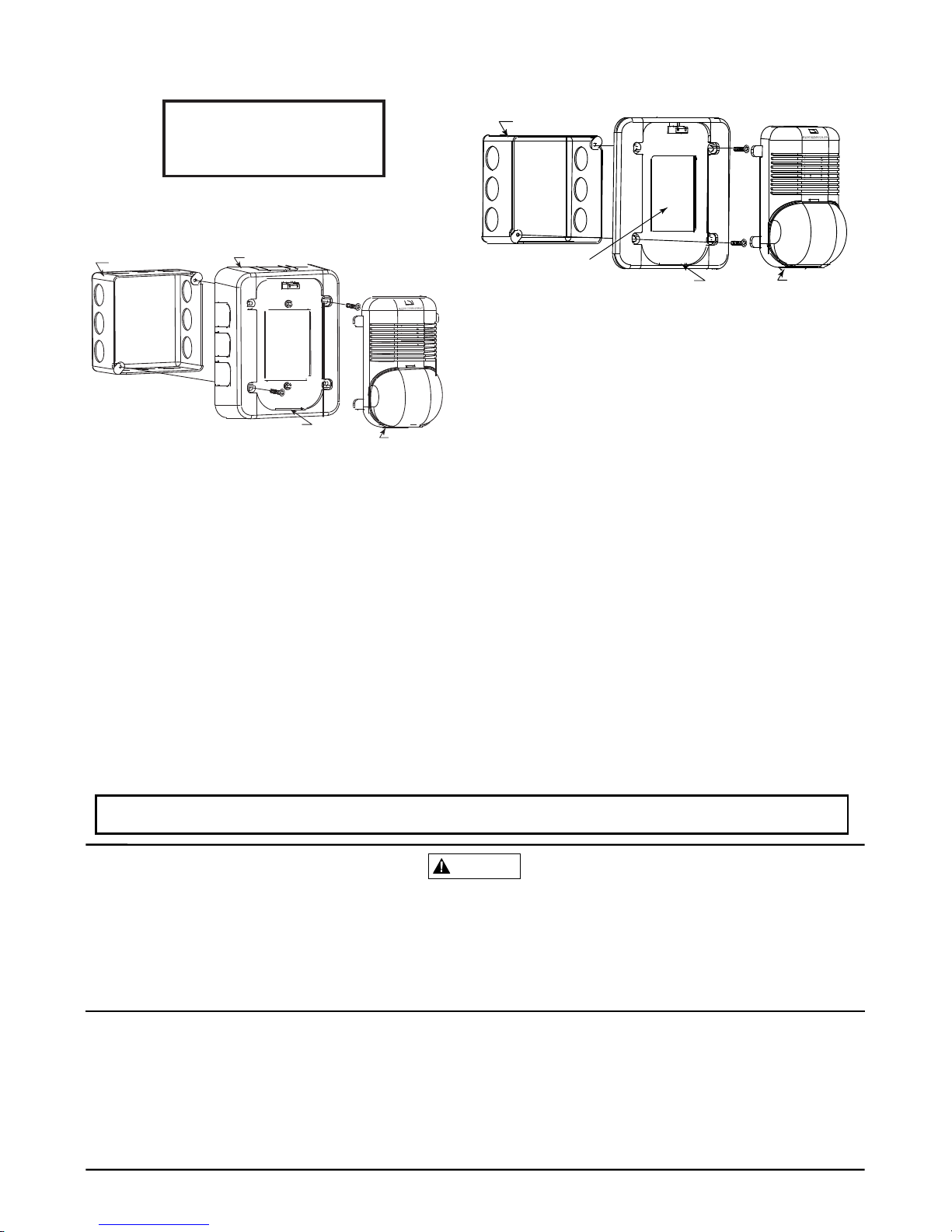
MOUNTING DIAGRAMS:
STROBE WITH UNIVERSAL MOUNTING PLATE
:
S
TROBE SURFACE
MOUNT:
1. Mount plate to back box using screws A, making sure wall
opening
is
equal to the plate
opening.
2. Complete field
wiring.
3. Insert locking rib into slot on
plate.
4. Press into plate, unit will make a “click” when it has locked
into place.
A
A
1. Mount skirt to back box with screws A.
2. Complete field
wiring.
3.
Insert locking rib on unit into slot on
skirt.
4. Press into skirt; unit will make a “click” when it has locked
into
place.
THE
LIMITATIONS O
F
The signal strobe may cause seizures. Individuals who have positive photic
response to visual stimuli with seizures, such as persons with epilepsy, should avoid
prolonged exposure to environments in which strobe signals, including this strobe, are
activated.
The signal strobe cannot operate from coded power supplies. The strobe must
have an uninterrupted source of power in order to operate correctly. Xi'an System
Sensor Electronics Ltd. recommends that the horn and signal strobe always be used
in combination so that the risks from any of the above limitations are minimized.
Ver.
B
WARNING
Note: Please dispose electronic waste following national or local
regulations after being scrapped or replaced. Do not discard.
Screw types used for mounting:
A = 8-32 x 3⁄4 flat
head
B = 6-32 x 15⁄16 pan
head
4-INCH BACK BOX
LOCKING RIB SLOT
LOCKING RIB
BBS
T
HREE-YEAR LIMITED WARRANT
Y
Xi'an System Sensor Electronics Ltd. warrants its enclosed strobe product to be free
from defects in materials and workmanship under normal use and service for a period
of three years from date of manufacture. Xi'an System Sensor Electronics Ltd. makes
no other express warranty for this strobe product. No agent, representative, dealer, o
r
employee of the Company has the authority to inc rease or alter the obligations o
r
limitations of this Warranty. The Company’s obligation of this Warranty shall be limited
to the repair or replacement of any part of the strobe product which is found to be
defective in materials or workmanship under normal use and service during the three
year period commencing with the date of manufacture. After contacting Xi'an System
Sensor for a Return Authorization number, send defective units postage prepaid to:
Xi'an System Sensor Electronics, Ltd. Repair Department, RA #__________,
28 Tuan Jie South Road, Xi’an Hi-t ech Develo pment Zo ne, 7100 75 China. Please
include a note describing the malfunction and suspected cause of failure. The
Company shall not be obligated to repair or replace units which are found to be
defective because of damage, unreasonable use, modifications, or alterations
occurring after the date of manufacture. In no case shall the Company be liable for
any consequential or incidental damages for breach of this or any other Warranty,
expressed or implied whatsoever, even if the loss or damage is caused by the
Company’s negligence or fault. Some states do not allow the exclusion or limitation of
incidental or consequential damages, so the above limitation or exclusion may not
apply to you. This Warranty gives you specific legal rights, and you may also have
other rights which vary from state to state.
LOCKING RIB SLOT
LOCKING RIB
4-INCH BACK BOX
A
A
W
A
LL OPENING MUST
EQU
A
LPLATEOPENING
The strobe will not work without power. If power is cut off for any reason, the
strobe will not provide the desired visual warning signal.
The signal strobe may not be seen. The electronic visual warning signal uses
some high light LED indicators. It flashes at least once every second. The strobe
must not be installed in direct sunlight or areas of high light intensity (over 60
foot candles) where the visual flash might be disregarded or not seen. The strobe
may not be seen by the visually impaired.
Please refer to insert for the Limitations of Fire Alarm Systems
 Loading...