

Page 1
INSTALLATION AND MAINTENANCE INSTRUCTIONS
SPCW8 8 Inch Dual Voltage Speaker
for Fire and General Signaling Systems
Ceiling Speaker: SPCW8 with listed enclosure
Intended for use with separately sold tile support bracket: SB-SPC8
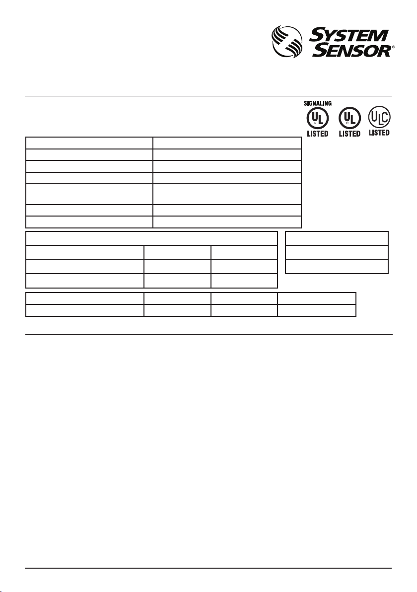
PRODUCT SPECIFICATIONS
Standard Operating Temperature: 32°F to 120°F (0°C to 49°C)
Humidity Range: 10 to 93% Non-condensing
Nominal Voltage: 25 Volts or 70.7 Volts
Maximum Supervisory Voltage: 50 VDC
Speaker Frequency Range:
Power Settings: ⅛, ¼, ½,1,2, 4, 8 Watts
Input terminal wire gauge: 12 to 18 AWG (2.5 mm²)
DIMENSIONS FOR PRODUCTS AND ACCESSORIES
Ceiling Speaker Diameter Depth
SPCW8 Speaker with grill 12.8” 325.1mm 2.7” 68.6mm
SPCW8 Speaker with back can 12.8” 325.1mm 4.2” 106.7mm
Tile Support Bracket Length Width Diameter opening
SB-SPC8 23.75” 603.3mm 4.125” 104.8mm 10.75” 273.1mm
NOTICE: This manual shall be left with the owner/user of this equipment.
BEFORE INSTALLING
Please read the System Sensor Voice Evacuation
Application Guide, which provides detailed information on speaker notification devices, wiring
and special applications. Copies of this manual are
available from System Sensor. NFPA 72, CAN/ULC
S524 and NEMA guidelines should be observed.
Important: The notification appliance used must be
tested and maintained following NFPA 72 requirements.
GENERAL DESCRIPTION
System Sensor series of notification appliances offer
a wide range of audible and visible devices for life
safety notification. The SPCW8 speaker is designed
to be used at either 25 or 70.7 volts, with field selectable tap settings from ⅛ to 8 Watts. These products are designed for high efficiency sound output
with low total harmonic distortion to offer high fidelity sound output.
Its clear audibility is designed to meet life safety
needs from fire to emergency communication messages. With its wide frequency range it can also
be used for general signaling such as paging and
background music. The SPCW8 speaker is listed
1 I56-0005-000R
05-20
400 – 4000 Hz (Fire Alarm)
200Hz – 15KHz (General Signaling)
to ANSI/UL 1480, CAN/ULC S541 and CSA C22.2
No. 205 requirements for public mode and general
signaling applications as well as ANSI/UL 2043 plenum rated. Speaker is suitable for indoor and damp
installations.
FIRE ALARM SYSTEM CONSIDERATIONS
All wiring must be installed in compliance with the
National Electrical Code (NEC , Canadian Electrical Code) and applicable local codes. System Sensor
recommends installing fire alarm speakers in compliance with NFPA 72, ANSI/UL 1480 , CAN/ULC
S524 and NEC 760.
WIRING AND MOUNTING
All wiring must be installed in compliance with the
National Electric Code and the local codes as well as
the authority having jurisdiction. Wiring must not
be of such length or wire size which would cause
the notification appliance to operate outside of its
published specifications. Improper connections can
prevent the system from alerting occupants in the
event of an emergency.
Wire sizes up to 12 AWG (3.31 mm²) may be connected to the wiring terminals. The terminals are
pre-set to accommodate 12 AWG wiring.
3825 Ohio Avenue, St. Charles, Illinois 60174
800/736-7672, FAX: 630/377-6495
www.systemsensor.com
MOUNTING BOX OPTIONS
SPEAKERS
Supplied Enclosure
I56-0005-000R
Page 2
CAUTION
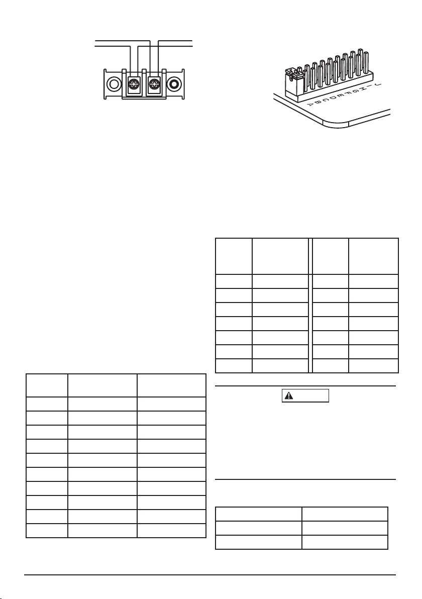
FIGURE 1. WIRING DIAGRAM
FROM PRECEDING
SPEAKER OR
FIRE ALARM
CONTROL PANEL
(FACP)
A0506-00
TO NEXT SPEAKER
OR END OF LINE
RESISTOR (EOLR)
FIGURE 2. JUMPER SETTINGS
FOR SPEAKER VOLUME
A0507-00
Make wire connections by stripping about 3/8” of
insulation from the end of the wire. Then slide the
bare end of the wire under the appropriate clamping plate and tighten the clamping plate screw.
1. Connect the speaker as shown in Figure 1.
2. Set speaker volume by selecting voltage input
jumpers as shown in Figure 2.
3. Mount according to instructions for the application’s appropriate configuration.
WIRING TERMINALS
1. Speaker Positive (+). Line in and out
2. Speaker Negative (COM). Line in and out.
NOTE: Do not loop electrical wiring under terminal
screws. Wires connecting the device to the control
panel must be broken at the device terminal connection in order to maintain electrical supervision.
SET SPEAKER VOLUME
In order to select the tap settings for given voltage
input (25V or 70.7V) select the jumper selections as
noted. Use the jumper connector to select tap setting for the desired speaker volume.
Jumper
Selection
Voltage Input
25V
Voltage Input
70V
A 8W
B 4W
C 2W
D 1W 8W
E ½W 4W
F ¼ W 2W
G ⅛W 1W
H ½W
I ¼ W
J ⅛W
AVAILABLE POWER SETTINGS
System Sensor offers a wide range of power settings
for your life safety needs, including ⅛,¼,½,1, 2, 4
and 8W.
Sound levels data per UL 1480 and CAN/ULC-S541
can be found in Table 1. Directional characteristics
can be found in Table 2.
TABLE 1. SOUND LEVELS FOR EACH TRANSFORMER POWER SETTING
Anechoic
Wattage
Setting
Reverberant
(dBA @ 10ft)
Wattage
Setting)
(dBA @
10ft)
⅛ W 75 ⅛ W 82
¼ W 78 ¼ W 85
½ W 81 ½ W 88
1 W 84 1 W 91
2 W 87 2 W 94
4 W 90 4 W 97
8W 93 8 W 10 0
Signal levels exceeding 130% rated signal voltage
can damage the speaker. Consequently, an incorrect
tap connection may cause speaker damage. This
means that if a 25V tap is selected when a 70.7V
amplifier is being used, speaker damage may result.
Therefore, be sure to select the proper taps for the
amplifier voltage/input power level combination
being used.
TABLE 2 DIRECTIONAL CHARACTERISTICS
Angle (degrees) Decibels
±30° -3dB
±60° -6dB
2 I56-0005-000R
05-20
Page 3

CAUTION
FIGURE 3 BACK CAN
KNOCKOUTS (5)
TIE-OFF TABS (4)
SCREW HOLES (8)
TIE-OFF SLOT (4)
HORSESHOE TAB (4)
FIGURE 4 REMOVING KNOCKOUTS
A0508-00
SUPPLIED BACK CAN
¾ inch knockouts are provided for conduit entry
way. Compatible with plenum rated cable and plenum whip flex conduit.
To remove the ¾ inch knockout, we recommend
you use a flat head screwdriver, place the blade of
the flat head screwdriver in the inner edge of the
knockout. Strike the screwdriver as you work your
way around as shown in Figure 4:
FLUSH MOUNTING INSTALLATION
1. Connect field wiring to terminals, as shown in
Figure 1.
2. Select the power tap settings using the jumper for
⅛, ¼, ½, 1, 2, 4, 8W.
3. Mount speaker to supplied back can using
mounting screws provided.
Factory finish should not be altered: Do not paint!
FIGURE 5 CEILING TILE WITH BACK CAN
A0509-00
CEILING TILE INSTALLATION (WITH BACK CAN)
1. Place ceiling tile with finished surface facing
up over a large garbage can (provides support and
saves clean up time).
2. Cut hole in the center of the ceiling tile using the
SB-SPC8 tile support opening as a template.
3. Flip the ceiling tile over and position the SB-SPC8
tile bridge on the unfinished side of the ceiling tile.
4. Punch out knockout in the supplied back can and
wire per the NEC. The back can is listed to accommodate plenum cable or plenum cable whip and
feed cable or whip through the knockout.
5. Install the SB-SPC8 tile bridge to the backcan
using the supplied clips and customer supplied
screws.
6. Connect field wiring to terminals, as shown in
Figure 1.
7. Select the power tap settings using the jumper for
⅛, ¼,½, 1, 2,4,8W.
8. Install the ceiling speaker using (4) 8-32 screws
provided with the ceiling speaker, sandwiching the
SB-SPC8 tile bridge and ceiling tile in between. The
screws anchor into the extruded threaded holes in
the SB-SPC8 tile bridge.
KNOCKOUTS (5)
SCREW HOLES (8)
HORSESHOE TAB (4)
A0510-00
3 I56-0005-000R
05-20
Page 4

Please refer to insert for the Limitations of Fire Alarm Systems
WARNING
THE LIMITATIONS OF SPEAKERS
Always make sure that the individual speakers
are tested after installation per NFPA regulations.
The speakers may not be heard. The loudness of
the speaker meets (or exceeds) current Underwriters
Laboratories’ standards. However, the speaker may
not alert a sound sleeper or one who has recently
used drugs or has been drinking alcoholic bever-
ages. The speaker may not be heard if it is placed
on a different floor from the person in hazard or
if placed too far away to be heard over the ambient noise such as traffic, air conditioners, machinery or music appliances that may prevent alert
persons from hearing the alarm. The speaker may
not be heard by persons who are hearing impaired.
Three-Year Limited Warranty
System Sensor warrants its enclosed product to be
free from defects in materials and workmanship under
normal use and service for a period of three years
from date of manufacture. System Sensor makes no
other express warranty for this product. No agent,
representative, dealer, or employee of the Company
has the authority to increase or alter the obligations
or limitations of this Warranty. The Company’s obligation of this Warranty shall be limited to the replacement of any part of the product which is found to be
defective in materials or workmanship under normal
use and service during the three year period commencing with the date of manufacture. After phoning System Sensor’s toll free number 800-SENSOR2
(736-7672) for a Return Authorization number, send
defective units postage prepaid to: Honeywell, 12220
4 I56-0005-000R
©2016 System Sensor. 05-20
Rojas Drive, Suite 700, El Paso TX 79936, USA.
Please include a note describing the malfunction
and suspected cause of failure. The Company shall
not be obligated to replace units which are found to
be defective because of damage, unreasonable use,
modifications, or alterations occurring after the date
of manufacture. In no case shall the Company be
liable for any consequential or incidental damages
for breach of this or any other Warranty expressed
or implied whatsoever, even if the loss or damage is
caused by the Company’s negligence or fault. Some
states do not allow the exclusion or limitation of
incidental or consequential damages, so the above
limitation or exclusion may not apply to you. This
Warranty gives you specific legal rights, and you may
also have other rights which vary from state to state.
 Loading...