

Page 1
INSTALLATION AND MAINTENANCE INSTRUCTIONS
SpectrAlert Selectable Output Series
Wall Speaker/Strobes for
Fire Protective Signaling Systems
For use with models: SP2R1224MC, SP2W1224MC and SP2R1224MCP.
U.S. Patent Nos. 5,593,569; 5,914,665; 5,850,178; 5,598,139; 6,049,446; 6,127,935; 6,522,261
Specifications: Speaker
Mechanical
Input Terminals: 12 to 18 AWG (3.31 to 0.82 mm2)
Speaker Size: 4 inches (101 mm)
Overall Dimensions: 8.25˝ × 4.9˝
Automatic selection for 12 or 24 volt rated operation
(DC or Full-Wave Rectified)
Electrical
For Strobes
Voltages: Regulated 12 DC/FWR and
Regulated 24 DC/FWR
Operational Voltage Ranges: 8-17.5 Volts and 16-33 Volts
Synchronous Applications
with MDL Module: 9-17.5 Volts and 17-33 Volts
Flash Rate: 1 flash per second
Operating Temperature: 32° F to 120° F (0° C to 49° C)
Storage Temperature: –20°C to 70°C
Operational Humidity Range: 10 – 93% RH (non-condensing)
Selectable Light Outputs: All candelas are selectable
via a manual slide switch.
12/24 Volt Applications: 15 or 15/75 candela
24 Volt Application: 15,15/75, 30, 75, 110 candela
15/75 is listed at 15 candela per UL 1971 but will pro
Maximum Supervisory
Voltage (Speaker): 50 VDC
Sound Output:
Sound output levels are established at Underwriters
Listings: UL S5512 (Strobe); UL S4048
NOTE for Strobes: Do not exceed; 1) 8-17.5 or 16-33 voltage
range limit; 2) maximum number of 70 strobe lights when
connecting the MDL Sync module with a maximum line impedance of 4 ohms per loop and; 3) maximum line impedance as required by the fire alarm control manufacturer.
NOTE: The SP2 Series is suitable for dry and damp environments.
3825 Ohio Avenue, St. Charles, Illinois 60174
1-800-SENSOR2, FAX: 630-377-6495
www.systemsensor.com
vide 75 candela on axis (straight ahead). 15, 30, 75, or
110 are rated for that candela.
Laboratories in their reverberant room. Always use the
sound output specified as UL Reverberant Room when
comparing products.
(Speaker/Strobe)
The models
voltage over the range of candela selections. The benefit to the customer is a high quality strobe device.
NOTICE: This manual shall be left with the owner/user of
this equipment.
General Description
The SpectrAlert SP2 series speaker/strobes are designed to
meet the requirements of most agencies governing these
devices, including: NFPA, ADA, The National Fire Alarm
Code, UL, CSFM, MEA. Also, check with your local Authority Having Jurisdiction for other codes or standards that
may apply.
The SpectrAlert SP2 series speakers can be operated with
distribution amplifiers having an output voltage of either
25 volts or 70.7 volts.
The speakers operate at any one of four input power levels.
The output sound level is selected at the time of installation, but can be changed, if necessary.
The speaker is also equipped with a capacitive input to allow for DC supervision.
The SpectrAlert SP2 series strobe can be installed in systems
using 12 or 24-volt panels having DC or full-wave rectified
(FWR) power supplies. The strobes can also be installed
in applications requiring synchronization (module MDL or
compatible equivalent required) or applications that do not
require synchronization (no module required).
SP2R1224MC, SP2W1224MC and SP2R1224MCP
incorporate a new patent-pending voltage booster design that has a more consistent flash bulb
Power Supply Considerations For Strobes
Panels typically supply DC filtered voltage or FWR (fullwave rectified) voltage. The system design engineer must
calculate the number of units used in a zone based on the
type of panel supply. Be certain the sum of all the device
currents do not exceed the current capability of the panel.
Calculations are based on using the device current found
in Table 2 and must be the current specified for the type of
panel power supply used.
Wire Sizes
The designer must be sure that the last device on the circuit
has sufficient voltage to operate the device within its rated
voltage. When calculating the voltage available to the last
device, it is necessary to consider the voltage drop due to
the resistance of the wire. The thicker the wire, the less the
voltage drop. Generally, for purposes of determining the
wire size necessary for the system, it is best to consider all
of the devices as “lumped” on the end of the supply circuit
(simulates “worst case”).
Typical wire size resistance:
18 AWG solid: Approximately 8 ohms/1,000 ft.
16 AWG solid: Approximately 5 ohms/1,000 ft.
14 AWG solid: Approximately 3 ohms/1,000 ft.
12 AWG solid: Approximately 2 ohms/1,000 ft.
D900-29-00 1 I56-1809-009R
Page 2
25.0V
70.7V
2W
1W
1/2W
1/4W
25.0V
70.7V
2W
1W
1/2W
1/4W
CORRECT
SW1
SW1
INCORRECT
2 W 1 W 1/2 W 1/4 W
84 81 78 75
UL
Reverberant
(dBA @ 10 ft.)
2 W 1 W 1/2 W 1/4 W
87 84 81 78
Anechoic
(dBA @ 10 ft.)
CAUTION
EXAMPLE: Assume you have 10 devices on a zone and
TO NEXT
STROBE OR EOL
INPUT FROM
POWER SUPPLY
INPUT FROM
AMPLIFIER
TO NEXT
SPEAKER OR EOL
STROBESPEAKER
each requires 50 mA average and 2000 Ft. of 14 AWG wiring (total length=outgoing+return). The voltage at the
end of the loop is 0.050 amps per device × 10 devices × 3
ohms/1,000 ft. × 2000 ft =3 volts drop.
The same number of devices using 12 AWG wire will produce only 2 volts drop. The same devices using 18 AWG
wire will produce 8 volts drop. Consult your panel manufacturer’s specifications, as well as SpectrAlert’s operating
voltage range to determine acceptable voltage drop.
Note: If class “A” wiring is installed, the wire length may be
up to 4 times the single wire length in this calculation.
Installation
All wiring must be installed in compliance with the National Electrical Code (NEC) and applicable local codes as
well as special requirements of the authority having jurisdiction, using the proper wire size. This also includes all
applicable NFPA Standards, ANSI/UL 1480, UL 1971 and
NEC 760.
Electrical
1. Connect the speaker/strobe as shown in Figure 1. Keep
in mind that even though the speaker and strobe are
a single mechanical unit, they are electrically independent and require separate power sources.
NOTE: Do NOT loop electrical wiring under terminal
screws. wires connecting the device to the control panel
must be broken at the device terminal connection in order to maintain electrical supervision.
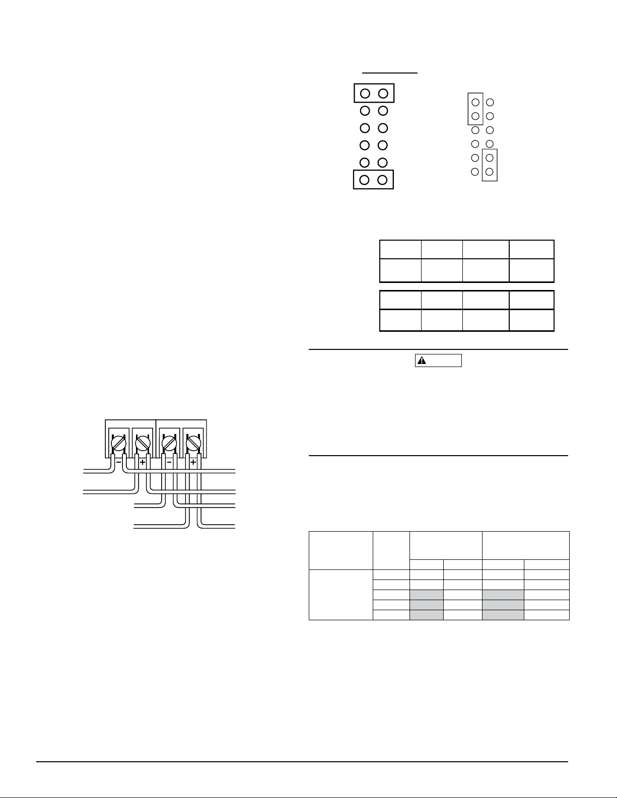
Figure 1. Electrical connections:
Figure 2. Speaker Voltage and Power Selection:
A0102-00
Table 1. Sound levels for each transformer power tap:
A0103-00
Signal levels exceeding 130% rated signal voltage can damage the speaker. Consequently, an incorrect tap connection
may cause speaker damage. This means that if a 25V tap
is selected when a 70.7V amplifier is being used, speaker
damage may result. Therefore, be sure to select the proper
taps for the amplifier voltage/input power level combination being used.
NOTE: Supply power for strobe must be continuous for
proper operation.
2. See Figure 2 as an example of how to select a
input when a 25 volt amplifier is being used. Notice that
the header, SW1, has two shunts. One shunt is used to
select either 25 or 70.7 volts input. The other shunt is
used to select input power of 1⁄4, 1⁄2, 1 or 2 Watts. Table 1
lists the UL reverberant and anechoic output sound levels
for each power tap on the SP2 series speaker/strobes.
D900-29-00 2 I56-1809-009R
A0101-00
1
⁄4 Watt
Table 2. Strobe current draw measurements – 12/24
Volt applications:
NOTE: All models were only tested at the 8-17.5 and 16-33
Volt-FWR/DC limits. This does not include the 80% lowend or 110% high-end voltage limits.
Model No.
SP2R1224MC
Speaker/Strobe
FWR Operating
Current–Strobe
Candela
Setting
15 112 64 127 59
15/75 135 74 127 69
30 93 90
75 158 160
110 208 209
(mA RMS)
12V 24V 12V 24V
DC Operatng
Current–Strobe
(mA RMS)
Page 3

4-INCH
B
ACK BOX
SNAP LEVER
LOCKING RIBLOCKING RIB SLOT
INSERT REMOVAL TOOL
Viewing Window
Candela Selections:
WARNING
Figure 3. For strobe candela selections, adjust slide
switch located on the rear of the product while watching the viewing window on the side of the reflector.
A0133-00
NOTE: SpectrAlert Selectable Output strobes, set at 15
and 15/75cd, automatically work on both 12V and 24V
power supplies.
NOTE: The strobe is not listed for 12V operating voltages
when set to 30, 75 or 110 candela. Use only those settings
marked as OK in this chart:
Permissible Candela Settings:
Candela
Setting
15 OK OK
15/75 OK OK
30 OK
75 OK
110 OK
Operating Voltage
12V 24V
Flush mount back box
The speaker/strobe can be flush mounted on a 4˝×4˝×
21/8˝ back box (Fig. 5) as follows:
A. Select the appropriate pair of diagonally opposite mount-
ing holes in the speaker grille that will be used to attach
the speaker/strobe to the back box. Do not insert any
mounting screws at this point.
B. Use two 8-32 × 13/4˝ pan head screws to attach the
speaker to the back box.
C. Plug the remaining two holes that will not be used for
attachment with the plugs provided.
NOTE: Two drywall screws (provided) may be used to
fasten the mounting plate to the wall. To use the drywall
screws, it will be necessary to first remove the strobe
and hinge the strobe module away from the mounting
plate (Fig. 7).
Figure 4: Reversible strobe module
A0105-01
Figure 5: Flush mount back box
When using a 12V panel, this device will yield required
light output only in the 15 or 15/75 candela setting.
Mounting
Reversible strobe module
Should the back box be located near an obstruction such as
a doorway, the strobe module is field-reversible (Fig. 4).
To reverse the strobe module: first remove the strobe from
the mounting plate (Fig. 6). Turn the module so that it is
upside down from its original position, re-insert the module into the mounting plate (be sure to insert the Locking
Tab into the slot), and press the module into the mounting
plate. The strobe module will make a “click” when it has
locked into place. Turn the entire assembly so that the word
“FIRE” is right side up. The unit can now be mounted.
A0106-00
Figure 6. Removal of strobes from mounting plates
To remove units from mounting plates, insert Quick Click
Removal Tool as shown to unlock snap. While pushing in
Removal Tool to release the snap, pull back on the strobe.
Hinge the strobe module, disengage the Locking Rib, and
lift the strobe away from the mounting plate.
A0100-00
D900-29-00 3 I56-1809-009R
Page 4

WARNING
Surface mount with BBS-SP2 back box skirt
4-INCH BACK BOX
DRYWALL SCREWS
(OPTIONAL)
BBS-SP2
DRYWALL
SCREWS
(OPTIONAL)
LOCKING RIB SLOT
An optional back box skirt is available to provide a finished
appearance. Mount the skirt to the back box using the mounting screws provided with the speaker/strobe as follows:
3
A. Use the two 8-32 × 1
/4˝ pan head screws to attach the
speaker to the back box.
B. Plug the two holes that will not be used for attachment,
using plugs provided.
Figure 6: Surface mount with SP2-BBS back box skirt
NOTE: Two drywall screws (provided) may be used to fasten the BBS-SP2 to the wall.
NOTE: The back box or back box with extension ring combination must be 4˝×4˝ and a minimum of 21/8˝ deep if
using a BBS-SP2.
NOTE: To surface mount the SP2 series speaker/strobe,
the minimum depth required in the back box/extension
ring combination, is 25/8˝.
Please refer to insert for the Limitations of Fire Alarm Systems
A0107-00
Figure 7: Mounting to irregular surfaces
A0108-00
The Limitations of Speaker/Strobes
If either of the voltage select or power select shunts is not plugged into one of the
appropriate option positions, the speaker will not sound and there will be no trouble
indication at the panel. Always make sure that the individual speakers are tested after
installation per NFPA regulations.
The speaker may not be heard. The loudness of the speaker meets (or exceeds) the
current Underwriters Laboratories’ standards. However, the speaker may not attract
the attention of a sound sleeper or one who has recently used drugs or has been
drinking alcoholic beverages. The speaker may not be heard if it is placed on a dif
ferent floor from the person in hazard or if placed too far away to be heard over the
ambient noise. Traffic, air conditioners, machinery, or music appliances may prevent
even alert persons from hearing the alarm. The speaker may not be heard by persons
who are hearing impaired.
Three-Year Limited Warranty
Syst em Sensor warrants its enclo sed prod uct to be fre e from de fects in materi als and workmanship under no rmal use and service for a period of three years
from dat e of manu facture. System Sensor makes no oth er express warranty for
this air duct smoke detect or. N o a gent, repre sentative, dealer, or empl oyee of
the Company has the autho rity to increase or alter the obligation s or limi tations
of this Warranty. The Company’s obl igation of this Warranty shall be l imited
to the replacem ent of a ny part of the product whi ch is fo und to b e defecti ve
in ma terials or workman ship under nor mal use and service d uring the three
year perio d commenci ng with the date of manufacture. Afte r p honing Syst em
Sensor’s toll free number 80 0-SENSO R2 ( 736-767 2) for a Return Authorization
number, send d efective units postage prepaid to: Syst em Sensor, Returns
SpectrAlert Speaker/Strobes have been tested and found to comply with the limits for a
Class B digital device, pursuant to part 15 of the FCC Rules. These limits are designed
to provide reasonable protection against harmful interference when the equipment
is operated in a commercial environment. This equipment generates, uses, and can
The signal strobe may not be seen. The electronic visual warning signal uses an
extremely reliable xenon flash tube. It flashes at least once every second. The strobe
must not be installed in direct sunlight or areas of high light intensity (over 60 foot
candles) where the visual flash might be disregarded or not seen. The strobe may not
be seen by the visually impaired.
The signal strobe may cause seizures. Individuals who have positive photoic response to visual stimuli with seizures, such as persons with epilepsy, should avoid
-
prolonged exposure to environments in which strobe signals, including this strobe,
are activated.
The signal strobe cannot operate from coded power supplies. Coded power supplies produce interrupted power. The strobe must have an uninterrupted source of
power in order to operate correctly. System Sensor recommends that the horn and
signal strobe always be used in combination so that the risks from any of the above
limitations are minimized.
Department , RA #___ _______ , 3825 Oh io Aven ue, St. Ch arles, IL 60174. Please
include a note descr ibing the malfu nction and susp ected cause of failure.
The C ompany shall not be ob ligated t o replace un its which a re found to b e
defective bec ause of damage, un reas onable us e, modific ations, or a lterations
occurring after the date of manuf acture. In no case sh all th e Company be
liable f or any consequent ial o r incidental damages for breac h of this or any
other Warranty, expressed or implied what soever, even if th e loss o r dama ge
is caused by the Company ’s negligence or fault. Some state s do not a llow th e
excl usion or li mitatio n of incide ntal or con sequential damages, so the ab ove
limitation or exclusion may n ot apply to you. T his Warranty gi ves you speci fic
legal ri ghts, and you may also have other right s which va ry from st ate to state.
FCC Statement
radiate radio frequency energy and, if not installed and used in accordance with the instruction manual, may cause harmful interference to radio communications. operation
of this equipment in a residential area is likely to cause harmful interference in which
case the user will be required to correct the interference at his own expense.
D900-29-00 4 I56-1809-009R
©2006 System Sensor
 Loading...