

Page 1
INSTALLATION AND MAINTENANCE INSTRUCTIONS
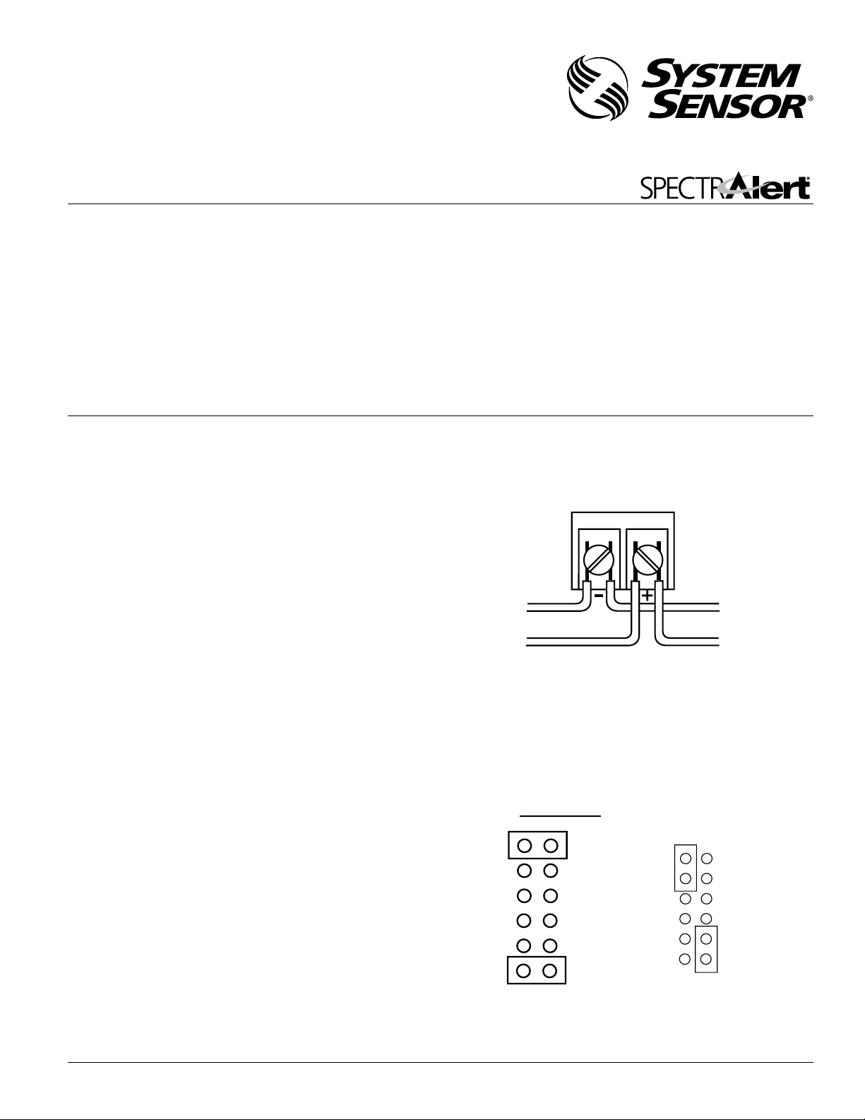
INPUT FROM
AMPLIFIER
TO NEXT
SPEAKER OR EOL
25.0V
70.7V
2W
1W
1/2W
1/4W
25.0V
70.7V
2W
1W
1/2W
1/4W
CORRECT
SW1
SW1
INCORRECT
I56-2610-002R
SpectrAlert SP201K Outdoor
Dual Voltage Transformer Speakers
for Fire Protective Signaling Systems
U.S. patent number: D424465
Specifications
Mechanical
Input Terminals: 12 to 18 AWG (3.31 to 0.82 mm
Speaker Size: 4 inches (101 mm)
Grille Size: 4
Outdoor Back Box: 6
13
/16˝ (122 mm)
5
/8˝×51/4˝×4˝
Electrical
Voltage Input: 25 volts or 70.7 volts (nominal)
Frequency Range: 400 – 4000 Hz
Operating Temperature Range: – 40°F to 150.8°F (– 40°C to 66°C)
Maximum Supervisory Voltage: 50 VDC
Input Power Settings:
1
/4, 1/2, 1 and 2 Watts
Listings: UL 1480; NEMA 3R
NOTICE: This manual shall be left with the owner/user of this
equipment.
Suitable for outdoor use in wet environments with outdoor back
box supplied with the product.
General Description
The National Fire Protection Association (NFPA) has published
standards and recommended practices for the speakers described
in this manual. As a result, the installer must be familiar with
these requirements as well as all local codes and special require
ments of the authority having jurisdiction.
2
)
Figure 1. Electrical connections:
-
3825 Ohio Avenue, St. Charles, Illinois 60174
800/736-7672, FAX: 630/377-6495
www.systemsensor.com
SP201K series speaker can be operated with distribution ampli
fiers having an output voltage of either 25 volts or 70.7 volts.
-
A0175-00
The speaker operates at any one of four input power levels. The
output sound level is selected at the time of installation, but can
be changed, if necessary.
The speaker is also equipped with a capacitive input to allow for
DC supervision.
Installation
Figure 2:
All wiring must be installed in compliance with the National
Electrical Code (NEC) and applicable local codes as well as
special requirements of the authority having jurisdiction, using
the proper wire size. This also includes all applicable NFPA
Standards, ANSI/UL 1480, and NEC 760.
Electrical
1. Connect the speaker as shown in Figure 1.
NOTE: Do not loop electrical wiring under terminal screws. Wires
connecting the device to the control panel must be broken
at the device terminal connection in order to maintain
electrical supervision.
2. See Figure 2 as an example of how to select a
when a 25 volt amplifier is being used. Notice that the header,
SW1, has two shunts. One shunt is used to select either 25 or
70.7 volts input. The other shunt is used to select input power
1
of
/4, 1/2, 1 or 2 Watts.
D900-41-00 1 I56-2610-002R
1
/4 Watt input
A0102-00
Page 2
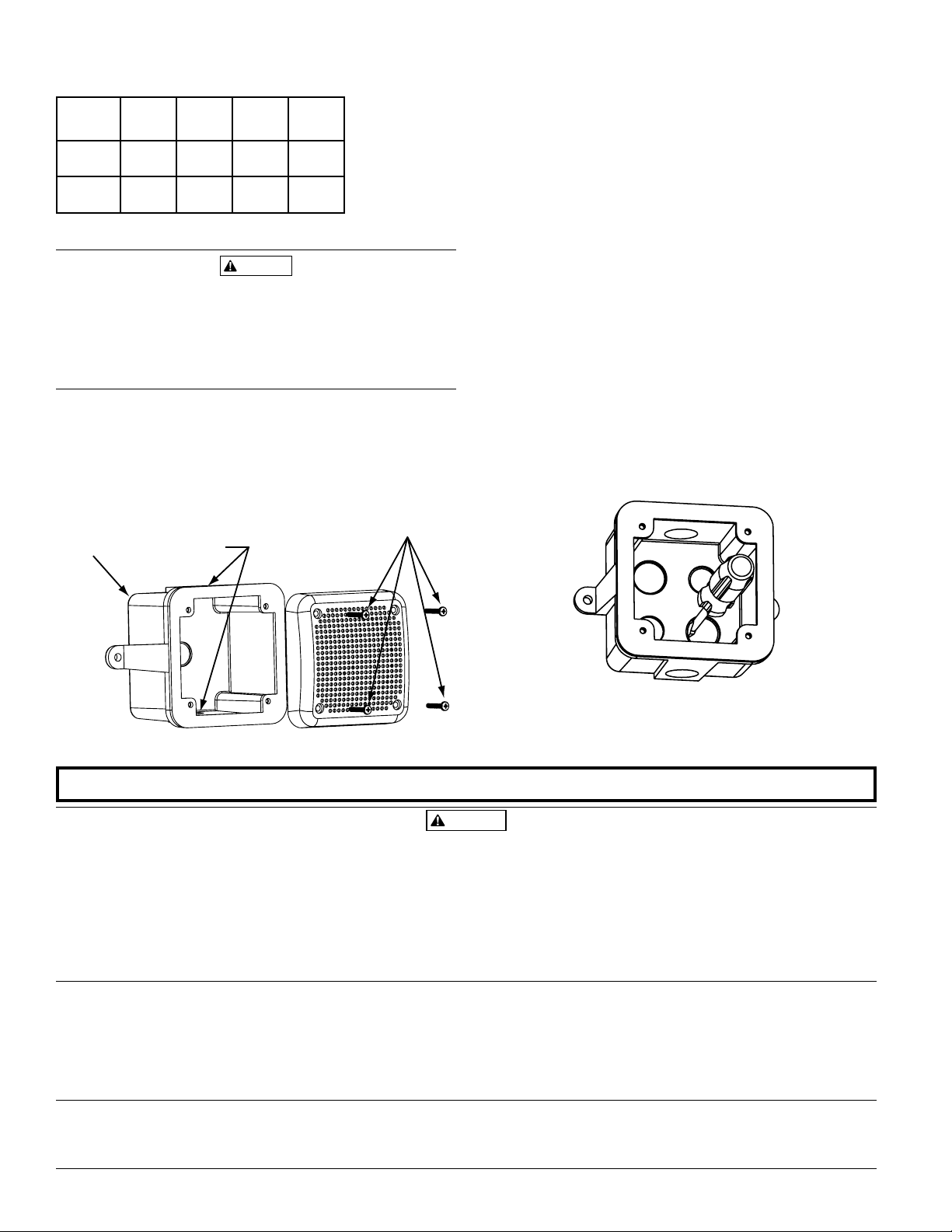
Table 1. Sound levels for each transformer power tap:
CAUTION
3
/4˝ NPT
Conduit
Entrance
Outdoor
Back
Box
1
3
/8˝ (4)
WARNING
INPUT
VOLTS
25.0 89 87 85 81
2 W 1 W1/2 W1/4 W
UL
Reverberant
(dBA @ 10 ft.)
70.7 90 87 84 81
Signal levels exceeding 130% rated signal voltage can damage the speaker. Consequently, an incorrect tap connection
may cause speaker damage. This means that if a 25V tap is
selected when a 70.7V amplifier is being used, speaker damage
may result. Therefore, be sure to select the proper taps for the
amplifier voltage/input power level combination being used.
Mounting
1. Mount the outdoor back box (supplied with product) in
desired location (see Figure 3).
2. Install
3
/4˝ NPT plug into unused conduit opening.
3. Complete field wiring.
4. Mount speaker to back box using 4 #8-32
×13/8˝ screws supplied
with product.
NOTE: The weatherproof or outdoor notification appliance
must be used with the supplied System Sensor outdoor
back box when installed in applications requiring the
appliance to be weatherproof or outdoor-listed. In such
applications, using a back box other than the System
Sensor outdoor back box will void the UL designation.
Figure 4. Knockout plug removal
1. If a rear conduit entry is required, remove the knockout plug
using a flat blade screwdriver as shown in Figure 4. Strike
sharply with a hammer to pierce the wall of the knockout plug.
Move to an adjacent wall section and repeat until the plug falls
out. Make sure that the back box is supported adequately dur
ing this operation to avoid injury.
2. To meet weatherproof or outdoor listing, the conduit entrance
must be gasketed.
3. Install
3
/4˝ NPT plugs (2) into unused conduit openings.
-
Figure 3:
A0346-00
Please refer to insert for the Limitations of Fire Alarm Systems
The horn and/or strobe will not work without power. The horn/strobe gets its power from the
fire/security panel monitoring the alarm system. If power is cut off for any reason, the horn/strobe
will not provide the desired audio or visual warning.
The horn may not be heard. The loudness of the horn meets (or exceeds) current Underwriters
Laboratories’ standards. However, the horn may not alert a sound sleeper or one who has recently
used drugs or has been drinking alcoholic beverages. The horn may not be heard if it is placed on a
different floor from the person in hazard or if placed too far away to be heard over the ambient noise
such as traffic, air conditioners, machinery or music appliances that may prevent alert persons from
hearing the alarm. The horn may not be heard by persons who are hearing impaired.
NOTE: Strobes must be powered continuously for horn operation.
System Sensor warrants its enclosed horn. strobe, or horn/strobe to be free from defects in materials
and workmanship under normal use and service for a period of three years from date of manu
facture. System Sensor makes no other express warranty for this horn, strobe, or horn/strobe. No
agent, representative, dealer, or employee of the Company has the authority to increase or alter
the obligations or limitations of this Warranty. The Company’s obligation of this Warranty shall be
limited to the repair or replacement of any part of the horn, strobe, or horn/strobe which is found
to be defective in materials or workmanship under normal use and service during the three year
period commencing with the date of manufacture. After phoning System Sensor’s toll free number
800-SENSOR2 (736-7672) for a Return Authorization number, send defective units postage prepaid
SpectrAlert Strobes and Horn/Strobes have been tested and found to comply with the limits for a
Class B digital device, pursuant to part 15 of the FCC Rules. These limits are designed to provide
reasonable protection against harmful interference when the equipment is operated in a com
mercial environment. This equipment generates, uses, and can radiate radio frequency energy
The Limitations of Horn/Strobes
Three-Year Limited Warranty
FCC Statement
Figure 4:
A0343-01
The signal strobe may not be seen. The electronic visual warning signal uses an extremely reliable
xenon flash tube. It flashes at least once every second. The strobe must not be installed in direct
sunlight or areas of high light intensity (over 60 foot candles) where the visual flash might be disre
garded or not seen. The strobe may not be seen by the visually impaired.
The signal strobe may cause seizures. Individuals who have positive photoic response to visual
stimuli with seizures, such as persons with epilepsy, should avoid prolonged exposure to environ
ments in which strobe signals, including this strobe, are activated.
The signal strobe cannot operate from coded power supplies. Coded power supplies produce
interrupted power. The strobe must have an uninterrupted source of power in order to operate cor
rectly. System Sensor recommends that the horn and signal strobe always be used in combination
so that the risks from any of the above limitations are minimized.
to: System Sensor, Returns Department, RA #__________, 3825 Ohio Avenue, St. Charles, IL 60174.
-
Please include a note describing the malfunction and suspected cause of failure. The Company
shall not be obligated to repair or replace units which are found to be defective because of dam
age, unreasonable use, modifications, or alterations occurring after the date of manufacture. In no
case shall the Company be liable for any consequential or incidental damages for breach of this or
any other Warranty, expressed or implied whatsoever, even if the loss or damage is caused by the
Company’s negligence or fault. Some states do not allow the exclusion or limitation of incidental or
consequential damages, so the above limitation or exclusion may not apply to you. This Warranty
gives you specific legal rights, and you may also have other rights which vary from state to state.
and, if not installed and used in accordance with the instruction manual, may cause harmful
interference to radio communications. Operation of this equipment in a residential area is likely
-
to cause harmful interference in which case the user will be required to correct the interference
at his own expense.
-
-
-
-
D900-41-00 2 I56-2610-002R
2005 System Sensor
©
 Loading...