

Page 1
INPUT FROM
AMPLIFIER
TO NEXT
SPEAKER OR EOL
25.0V
70.7V
2W
1W
1/2W
1/4W
25.0V
70.7V
2W
1W
1/2W
1/4W
CORRECT
SW1
SW1
INCORRECT
INSTALLATION AND MAINTENANCE INSTRUCTIONS
SpectrAlert SP200 Series
Dual Voltage Transformer Speakers
for Fire Protective Signaling Systems
For use with the following models: SP200W, SP201R, SP201W
U.S. patent number: D424465
3825 Ohio Avenue, St. Charles, Illinois 60174
800/736-7672, FAX: 630/377-6495
Specifications
Mechanical
Input Terminals: 12 to 18 AWG (3.31 to 0.82 mm
2
)
Speaker Size: 4 inches (101 mm)
Grille Size
Round: 6
Square: 4
7
/8″ (187 mm)
7
/8″ (127 mm)
Electrical
Voltage Input: 25 volts or 70.7 volts (nominal)
Maximum Supervisory Voltage: 50 VDC
Frequency Range: 400 – 4000 Hz
Operating Temperature Range: 32° to 120°F (0° to 49°C)
Power:
1
/4, 1/2, 1 and 2 Watts
Listings: UL S4048
Storage Temperature: –20°C to 70°C
Operational Humidity Range: 10
– 93% RH (non-condensing)
NOTE: The SP200 Series is suitable for dry and humid environments. Not suitable for use in air handling spaces.
NOTICE: This manual shall be left with the owner/user of this equipment.
General Description
The National Fire Protection Association (NFPA) has published
standards and recommended practices for the speakers described
in this manual. As a result, the installer must be familiar with
these requirements as well as all local codes and special require
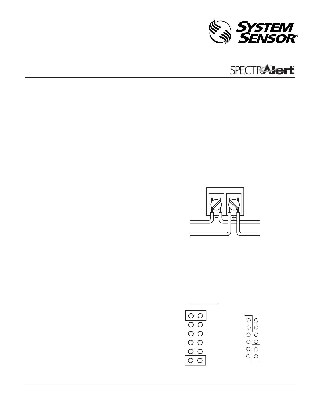
Figure 1.
Electrical
connections:
-
ments of the authority having jurisdiction.
www.systemsensor.com
SP200 series speakers can be operated with distribution amplifiers
A0175-00
having an output voltage of either 25 volts or 70.7 volts.
2. See Figure 2 as an example of how to select a 1/4 Watt input
The speakers operate at any one of four input power levels. The
output sound level is selected at the time of installation, but can
be changed, if necessary.
when a 25 volt amplifier is being used. Notice that the header,
SW1, has two shunts. One shunt is used to select either 25 or
70.7 volts input. The other shunt is used to select input power
1
of
/4, 1/2, 1 or 2 Watts.
The speaker is also equipped with a capacitive input to allow for
DC supervision.
Figure 2:
Installation
All wiring must be installed in compliance with the National
Electrical Code (NEC) and applicable local codes as well as
special requirements of the authority having jurisdiction, using
the proper wire size. This also includes all applicable NFPA
Standards, ANSI/UL 1480, and NEC 760.
Electrical
1. Connect the speaker as shown in Figure 1.
NOTE: Do not loop electrical wiring under terminal screws.
D400-69-00 1 I56-1217-008R
Wires connecting the device to the control panel must
be broken at the device terminal connection in order to
maintain electrical supervision.
A0102-00
Page 2
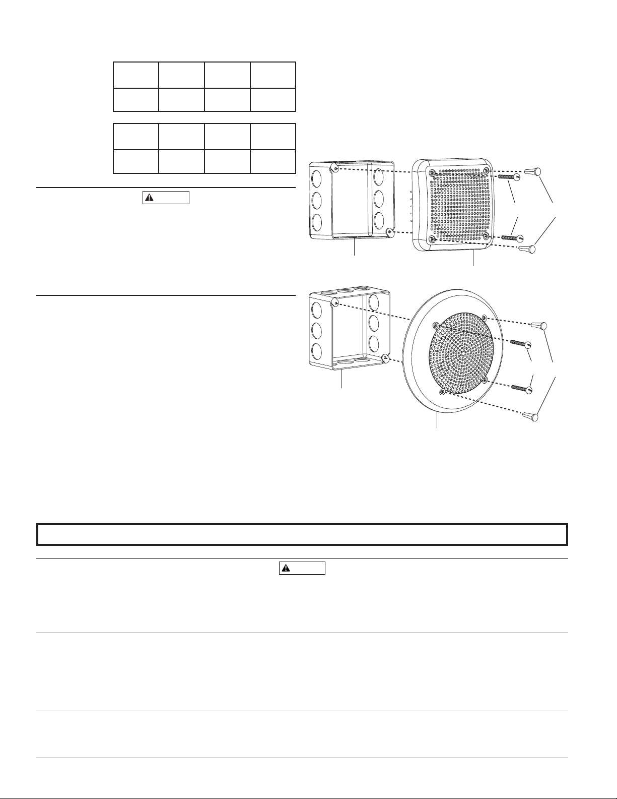
Table 1. Sound levels for each transformer power tap:
CAUTION
WARNING
UL
2 W 1 W
1
/2 W
Reverberant
(dBA @ 10 ft.)
84 81 78 75
1
/4 W
Mounting
See Figure 3. The speaker can be flush mounted on a 4
21/8″ back box, as follows:
A. Use the two 8-32
× 13/4″ screws, provided, to attach the speaker
to the back box.
B. Plug the remaining two holes that
will not be used for attach-
ment with the plugs provided.
″ × 4″ ×
Anechoic
(dBA @ 10 ft.)
2 W 1 W
1
/2 W
87 84 81 78
1
/4 W
Signal levels exceeding 130% rated signal voltage can damage the speaker. Consequently, an incorrect tap connection
may cause speaker damage. This means that if a 25V tap
is selected when a 70.7V amplifier is being used, speaker
damage may result. Therefore, be sure to select the proper
taps for the amplifier voltage/input power level combination
being used.
Mechanical
Two screws are included for attaching the speaker to the electrical
junction box.
NOTE: If surface mounting is required, an extension ring will be
necessary to give proper depth for mounting the speaker.
The minimum depth required, in the backbox/extension
ring combination, is 2
backbox and 4
″ × 4″ extension ring that gives an interior
depth of at least 2
5
/8″. Any combination of 4″ × 4″
5
/8″ may be used.
Figure 3:
4˝ × 4˝ × 2-1/8˝
BACKBOX
4˝ × 4˝ × 2-1/8˝
BACKBOX
SPEAKER
SP200 SERIES
8-32
SCREWS
SPEAKER
SP201 SERIES
8-32
SCREWS
FILL
PLUGS
A0176-02
FILL
PLUGS
A0177-01
Please refer to insert for the Limitations of Fire Alarm Systems
If either of the voltage select or power select shunts is not plugged into one of the appropriate
option positions, the speaker will not sound and there will be no trouble indication at the panel.
Always make sure that the individual speakers are tested after installation per NFPA regulations.
The speaker may not be heard. The loudness of the speaker meets (or exceeds) the current
Underwriters Laboratories’ standards. However, the speaker may not attract the attention of a
System Sensor warrants its enclosed horn. strobe, or horn/strobe to be free from defects in materials
and workmanship under normal use and service for a period of three years from date of manu
facture. System Sensor makes no other express warranty for this horn, strobe, or horn/strobe. No
agent, representative, dealer, or employee of the Company has the authority to increase or alter
the obligations or limitations of this Warranty. The Company’s obligation of this Warranty shall be
limited to the repair or replacement of any part of the horn, strobe, or horn/strobe which is found
to be defective in materials or workmanship under normal use and service during the three year
period commencing with the date of manufacture. After phoning System Sensor’s toll free number
800-SENSOR2 (736-7672) for a Return Authorization number, send defective units postage prepaid
SpectrAlert Strobes and Horn/Strobes have been tested and found to comply with the limits for a
Class B digital device, pursuant to part 15 of the FCC Rules. These limits are designed to provide
reasonable protection against harmful interference when the equipment is operated in a com
mercial environment. This equipment generates, uses, and can radiate radio frequency energy
D400-69-00 2 I56-1217-008R
The Limitations of Speakers
Three-Year Limited Warranty
FCC Statement
sound sleeper or one who has recently used drugs or has been drinking alcoholic beverages. The
speaker may not be heard if it is placed on a different floor from the person in hazard or if placed
too far away to be heard over the ambient noise. Traffic, air conditioners, machinery, or music
appliances may prevent even alert persons from hearing the alarm. The speaker may not be heard
by persons who are hearing impaired.
to: System Sensor, Returns Department, RA #__________, 3825 Ohio Avenue, St. Charles, IL 60174.
-
Please include a note describing the malfunction and suspected cause of failure. The Company
shall not be obligated to repair or replace units which are found to be defective because of dam
age, unreasonable use, modifications, or alterations occurring after the date of manufacture. In no
case shall the Company be liable for any consequential or incidental damages for breach of this or
any other Warranty, expressed or implied whatsoever, even if the loss or damage is caused by the
Company’s negligence or fault. Some states do not allow the exclusion or limitation of incidental or
consequential damages, so the above limitation or exclusion may not apply to you. This Warranty
gives you specific legal rights, and you may also have other rights which vary from state to state.
and, if not installed and used in accordance with the instruction manual, may cause harmful
interference to radio communications. Operation of this equipment in a residential area is likely
-
to cause harmful interference in which case the user will be required to correct the interference
at his own expense.
2004 System Sensor
©
-
 Loading...