

Page 1

SpectrAlert SP2 Series
Wall Speaker/Strobes for
Fire Protective Signaling Systems
INSTALLATION AND MAINTENANCE INSTRUCTIONS
3825 Ohio Avenue, St. Charles, Illinois 60174
1-800-SENSOR2, FAX: 630-377-6495
www.systemsensor.com
NOTICE: This manual shall be left with the owner/user of
this equipment.
General Description
The National Fire Protection Association (NFPA) has published standards and recommended practices for the speaker/strobes described in this manual. As a result, the
installer must be familiar with these requirements as well
as all local codes and special requirements of the authority
having jurisdiction.
The SpectrAlert SP2 series speakers can be operated with
distribution amplifiers having an output voltage of either
25 volts or 70.7 volts.
The speakers operate at any one of four input power levels.
The output sound level is selected at the time of installation, but can be changed, if necessary.
The speaker is also equipped with a capacitive input to
allow for DC supervision.
The SpectrAlert SP2 series strobe can be installed in systems
using 24-volt panels having DC or full-wave rectified (FWR)
power supplies. The strobes can also be installed in applications requiring synchronization (MDL required) or applications that do not require synchronization (no module
required).
The SpectrAlert SP2 series speaker/strobes are designed to
meet the requirements of most agencies governing these
devices, including: NFPA, ADA, The National Fire Alarm
Code, UL, CSFM, MEA. Also, check with your local
Authority Having Jurisdiction for other codes or standards
that may apply.
Power Supply Considerations For Strobes
Panels typically supply DC filtered voltage or FWR (fullwave rectified) voltage. The system design engineer must
D690-01-00 1 I56-1368-005R
For use with the following models: SP2R2415, SP2R2430, SP2R241575, SP2R2475, SP2R24110,
SP2W2415, SP2W2430, SP2W241575, SP2W2475, SP2W24110
U.S. Patent Nos. 5,593,569; 5.914,665; 5,850,178; 5,598,139; 6,049,446; 6,127,935
Specifications: Speaker
Mechanical
Input Terminals: 12 to 18 AWG (3.31 to 0.82 mm2)
Speaker Size: 4 inches (101 mm)
Overall Dimensions: 8.25″ x 4.9″
Electrical
Voltage Input: 25 volts or 70.7 volts (nominal)
Frequency Range: 400 – 4000 Hz
Power:
1
⁄4, 1⁄2, 1 and 2 Watts
Operating
Temperature Range: 32° to 120°F (0° to 49°C)
Listings: UL S4048 (Speaker/Strobe), S5512 (Strobe)
Note for Strobes: Do not exceed 1) 16-33 Voltage range limit, 2) Maximum number of 70 strobe lights when connecting
the MDL Sync module with a maximum line impedance of 4 Ohms per loop and 3) Maximum line impedance as required
by the fire alarm control manufacturer.
Specifications: Strobe
Voltage Range: DC or Full-Wave Rectified
20 to 30 volts, (21 to 30 volts with MDL
module)
Flash Rate: 1 flash per second
Light Output: Models with 1575 are listed at 15 candela
per UL1971 but will provide 75 candela on
axis (straight ahead).
Models with 15, 30, 75 or 110 are rated for
that candela.
calculate the number of units used in a zone based on the
type of panel supply. Be certain the sum of all the device
currents do not exceed the current capability of the panel.
Calculations are based on using the device current found in
Table 2 and must be the current specified for the type of
panel power supply used.
Wire Sizes
The designer must be sure that the last device on the circuit has sufficient voltage to operate the device within its
rated voltage. When calculating the voltage available to the
last device, it is necessary to consider the voltage drop due
to the resistance of the wire. The thicker the wire, the less
the voltage drop. Generally, for purposes of determining
the wire size necessary for the system, it is best to consider all of the devices as “lumped” on the end of the supply
circuit (simulates “worst case”).
Typical wire size resistance:
18 AWG solid: Approximately 8 ohms/1,000 ft.
16 AWG solid: Approximately 5 ohms/1,000 ft.
14 AWG solid: Approximately 3 ohms/1,000 ft.
12 AWG solid: Approximately 2 ohms/1,000 ft.
Example: Assume you have 10 devices on a zone and each
requires 50 mA average and 2000 Ft. of 14 AWG wiring
(total length=outgoing+return). The voltage at the end of
the loop is 0.050 amps per device × 10 devices × 3
ohms/1,000 ft. × 2000 ft =3 volts drop.
The same number of devices using 12 AWG wire will produce only 2 volts drop. The same devices using 18 AWG
wire will produce 8 volts drop. Consult your panel manufacturer’s specifications, as well as SpectrAlert’s operating
voltage range to determine acceptable voltage drop.
Note: If class “A” wiring is installed, the wire length may
be up to 4 times the single wire length in this calculation.
Page 2
Signal levels exceeding 130% rated signal voltage can
damage the speaker. Consequently, an incorrect tap connection may cause speaker damage. This means that if a
25V tap is selected when a 70.7V amplifier is being used,
speaker damage may result. Therefore, be sure to select
the proper taps for the amplifier voltage/input power
level combination being used.
2 W 1 W 1/2 W 1/4 W
84 81 78 75
UL
Reverberant
(dBA @ 10 ft.)
2 W 1 W 1/2 W 1/4 W
87 84 81 78
Anechoic
(dBA @ 10 ft.)
Installation
All wiring must be installed in compliance with the
National Electrical Code (NEC) and applicable local codes
as well as special requirements of the authority having
jurisdiction, using the proper wire size. This also includes
all applicable NFPA Standards, ANSI/UL 1480, UL 1971 and
NEC 760.
Electrical
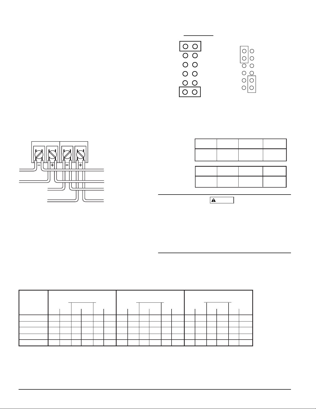
1. Connect the speaker/strobe as shown in Figure 1. Keep
in mind that even though the speaker and strobe are a
single mechanical unit, they are electrically independent
and require separate power sources.
NOTE: Do NOT loop electrical wiring under terminal
screws. Wires connecting the device to the control
panel must be broken at the device terminal connection in order to maintain electrical supervision.
NOTE: Supply power for strobe must be continuous for
proper operation.
2. See Figure 2 as an example of how to select a
1
⁄4
Watt
input when a 25 volt amplifier is being used. Notice that
the header, SW1, has two shunts. One shunt is used to
select either 25 or 70.7 volts input. The other shunt is
used to select input power of
1
⁄4, 1⁄2, 1 or 2 Watts. Table 1
lists the UL reverberant and anechoic output sound levels for each power tap on the SP2 series speaker/strobes.
Figure 1. Electrical connections:
Figure 2. Voltage and Power Selection:
25.0V
70.7V
2W
1W
1/2W
1/4W
25.0V
70.7V
2W
1W
1/2W
1/4W
CORRECT
SW1
SW1
INCORRECT
TO NEXT
STROBE OR EOL
INPUT FROM
POWER SUPPLY
INPUT FROM
AMPLIFIER
TO NEXT
SPEAKER OR EOL
STROBESPEAKER
Table 1. Sound levels for each transformer
power tap:
CAUTION
DC FWR DC FWR DC FWR
50 61 43 60 38 60
56 65 49 64 44 62
78 84 67 82 58 72
145 170 123 159 102 141
169 220 140 191 115 174
15
15/75
30
75
110
AVERAGE CURRENT (mA)
24V Models
20V 24V 30V
DC FWR DC FWR DC FWR
135 204 135 208 135 185
150 199 150 207 150 198
183 201 183 219 183 216
350 440 340 460 330 480
460 560 450 570 420 620
PEAK CURRENT (mA)
24V Models
20V
24V
30V
DC FWR DC FWR DC FWR
97 129 116 152 147 198
97 135 116 164 147 211
97 129 116 152 147 198
190 240 230 280 290 380
190 230 220 290 290 370
IN RUSH CURRENT (mA)
24V Models
20V 24V 30V
Candela
Table 2. Strobe current draw measurements:
D690-01-00 2 I56-1368-005R
Page 3
D690-01-00 3 I56-1368-005R
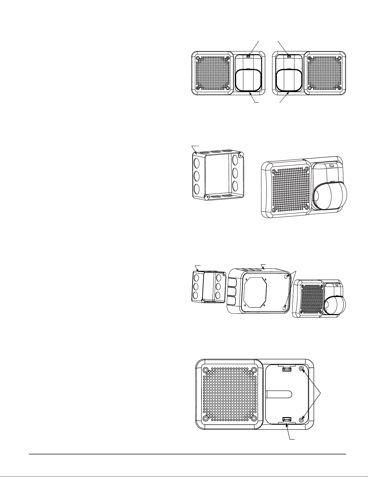
Mounting
Reversible strobe module
Should the back box be located near an obstruction such as
a doorway, the strobe module is field-reversible (Fig. 3).
To reverse the strobe module: insert screwdriver, as shown
in Fig. 3, to unlock snap. While pushing in the screwdriver, pull back on the strobe module. Hinge the strobe module, disengage the Locking Rib and lift the module away
from the mounting plate. Turn the module so that it is
upside down from its original position, re-insert the module into the mounting plate (be sure to insert the Locking
Rib into the slot), and press the module into the mounting
plate. The strobe module will make a “click” when it has
locked into place. Turn the entire assembly so that the word
“FIRE” is right side up. The unit can now be mounted.
Flush mount back box
The speaker/strobe can be flush mounted on a 4″ × 4″ ×
21/8″ back box (Fig. 4) as follows:
A. Select the appropriate pair of diagonally opposite
mounting holes in the speaker grille that will be used to
attach the speaker/strobe to the back box. Do not insert
any mounting screws at this point.
B. Plug the two holes that will not be used for attachment,
using two 8-32 × 13/4″ pan head screws and hex-nuts pro-
vided.
C. Use the two remaining 8-32 × 13/4″ pan head screws to
attach the speaker to the back box.
NOTE: Tw o drywall screws (provided) may be used to fas-
ten the mounting plate to the wall. To use the drywall screws, it will be necessary to first loosen the
strobe screw and hinge the strobe module away
from the mounting plate.
Surface mount with BBS-SP2 back box skirt
An optional back box skirt is available to provide a finished
appearance. Mount the skirt to the back box using the mounting screws provided with the speaker/strobe as follows:
A. Select the appropriate pair of diagonally opposite
mounting holes in the speaker grille that will be used to
attach the speaker/strobe to the back box. Do not insert
any mounting screws at this point.
B. Plug the two holes that will not be used for attachment,
using two 8-32 × 13/4″ pan head screws and hex nuts pro-
vided.
C. Use the two remaining 8-32 × 13/4″ pan head screws to
attach the speaker to the back box.
NOTE: Tw o drywall screws (provided) may be used to fas-
ten the BBS-SP2 to the wall.
NOTE: The back box or back box with extension ring com-
bination must be 4″ × 4″ and a minimum of 21/8″
deep if using a BBS-SP2.
NOTE: To surface mount the SP2 series speaker/strobe,
the minimum depth required in the back
box/extension ring combination, is 25/8″.
Figure 4: Flush mount back box
Figure 5: Surface mount with SP2-BBS back box skirt
Figure 3: Reversible strobe module
Figure 6: Mounting to irregular surfaces
A78-2680-00
A78-2679-00
A78-2678-00
A78-2681-00
INSERT SCREWDRIVER
TO REMOVE
LOCKING RIB
X
BO
4-INCH BAC
K
4-INCH BACK BOX
BBS-SP2
DRYWALL SCREWS
(OPTIONAL)
DRYWALL
SCREWS
(OPTIONAL)
LOCKING RIB SLOT
Page 4
D690-01-00 4 I56-1368-005R
©
System Sensor 2002
Three-Year Limited Warranty
System Sensor warrants its enclosed speaker to be free from defects in
materials and workmanship under normal use and service for a period of
three years from date of manufacture. System Sensor makes no other
express warranty for this speaker. No agent, representative, dealer, or
employee of the Company has the authority to increase or alter the obligations or limitations of this Warranty. The Company’s obligation of this
Warranty shall be limited to the repair or replacement of any part of the
speaker which is found to be defective in materials or workmanship under
normal use and service during the three year period commencing with the
date of manufacture. After phoning System Sensor’s toll free number 800SENSOR2 (736-7672) for a Return Authorization number, send defective
units postage prepaid to: System Sensor, Returns Department, RA
#__________, 3825 Ohio Avenue, St. Charles, IL 60174. Please include a
note describing the malfunction and suspected cause of failure. The
Company shall not be obligated to repair or replace units which are found
to be defective because of damage, unreasonable use, modifications, or
alterations occurring after the date of manufacture. In no case shall the
Company be liable for any consequential or incidental damages for breach
of this or any other Warranty, expressed or implied whatsoever, even if the
loss or damage is caused by the Company’s negligence or fault. Some
states do not allow the exclusion or limitation of incidental or consequential damages, so the above limitation or exclusion may not apply to
you. This Warranty gives you specific legal rights, and you may also have
other rights which vary from state to state.
If either of the voltage select or power select shunts is not plugged into
one of the appropriate option positions, the speaker will not sound and
there will be no trouble indication at the panel. Always make sure that the
individual speakers are tested after installation per NFPA regulations.
The speaker may not be heard. The loudness of the speaker meets (or
exceeds) the current Underwriters Laboratories’ standards. However, the
speaker may not attract the attention of a sound sleeper or one who has
recently used drugs or has been drinking alcoholic beverages. The speaker may not be heard if it is placed on a different floor from the person in
hazard or if placed too far away to be heard over the ambient noise.
Traffic, air conditioners, machinery, or music appliances may prevent even
alert persons from hearing the alarm. The speaker may not be heard by
persons who are hearing impaired.
The signal strobe may not be seen. The electronic visual warning signal
The Limitations of Speaker/Strobes
WARNING
uses an extremely reliable xenon flash tube. It flashes at least once every
second. The strobe must not be installed in direct sunlight or areas of high
light intensity (over 60 foot candles) where the visual flash might be disregarded or not seen. The strobe may not be seen by the visually
impaired.
The signal strobe may cause seizures. Individuals who have positive
photic response to visual stimuli with seizures, such as persons with
epilepsy, should avoid prolonged exposure to environments in which
strobe signals, including this strobe, are activated.
The signal strobe cannot operate from coded power supplies. Coded
power supplies produce interrupted power. The strobe must have an uninterrupted source of power in order to operate correctly. System Sensor recommends that the horn and signal strobe always be used in combination
so that the risks from any of the above limitations are minimized.
Please refer to insert for the Limitations of Fire Alarm Systems
FCC Statement
NOTE: This equipment has been tested and found to comply with the limits for a Class A digital
device, pursuant to part 15 of the FCC Rules. These limits are designed to provide reasonable protection against harmful interference when the equipment is operated in a commercial environment.
This equipment generates, uses, and can radiate radio frequency energy and, if not installed and
used in accordance with the instruction manual, may cause harmful interference to radio communications. Operation of this equipment in a residential area is likely to cause harmful interference
in which case the user will be required to correct the interference at his own expense.
 Loading...